6
Connector Function Description
ATX P. 20 pin Standard ATX power input connector
BIOS BIOS (Basic Input Output System)
Bank 0 SIMM Socket(Single In-line Memory Module ) J15, J16
Bank 1 SIMM Socket(Single In-line Memory Module ) J14, J9
Bank 2 SIMM Socket(Single In-line Memory Module ) J8, J7
Bank 3 SIMM Socket(Single In-line Memory Module ) J6, J5
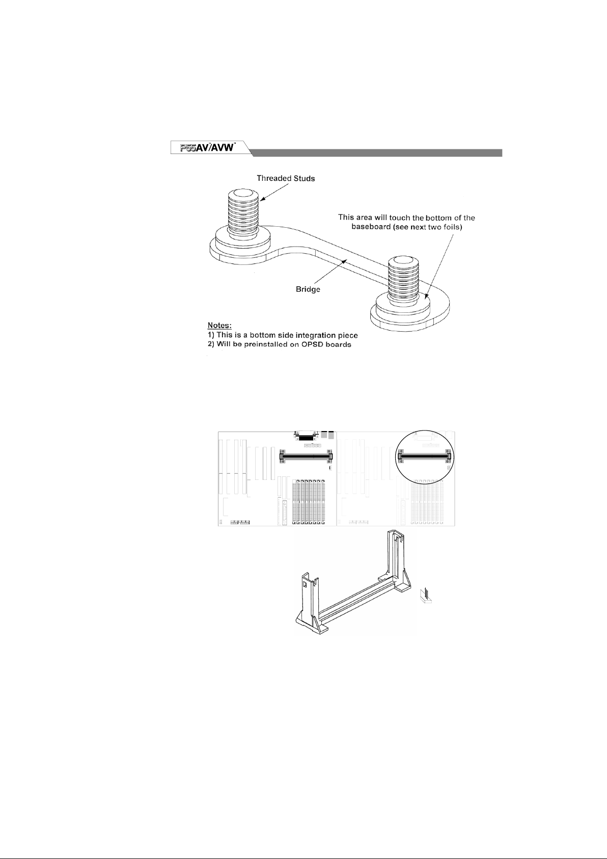
Slot1 Processor Retention Mechanism
FDD 34 pin Floppy Disk Drive with key protect connector
LPT 25 pin Parallel D-Sub connector
IR 6 pin pin-header connector
ISA 4 x ISA(Industrial Standard Architecture) 98 pin expansion slot
FAN JP1 Fan Power connector
JP18 Remote Power On/Off connector
KB 6 pin PS2 keyboard Mini-DIN connector
P. IDE40 pin Primary IDE with key protect connector
PCI 3 x PCI version 2.1 compliance 120 pin PCI (Peripheral
Component Interface)expansion slot
RAIDBUS 60 pin extension slot for working with RAIDBUS 1130 adapter
P. Control Front panel signal control connector
RST—Reset Switch
SCSI—SCSI detect LED
IDE—IDE detect LED
SMI—System Management Interface switch
LED—Power-on LED
Speaker—Speaker connector
Keylock—Keylock switch connector
PS2 6 pin PS2 mouse Mini-DIN connector
S. IDE 40 pin Secondary IDE with key protect connector
S1 9 pin Serial 1 D-Sub connector
S2 9 pin Serial 2 D-Sub connector
U. SCSI 50 pin Ultra SCSI with key protect connector
USB Two 4 pin Universal Serial Bus connector for USBA & USBB
W. SCSI 68 pin Wide SCSI with key protect connector