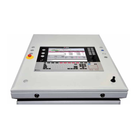
ProFire PF3100 FARC User manual

PROFIRENERGY.COM | 1.855.PRO.FIRE
November 26, 2020
1
PF3100 FARC USER GUIDE v5.0
This user guide contains a general overview of the PF3100 FARC system features and operation. For more specific BMS related
operation please review the PF3100 BMS operating manual. This guide is applicable to the NA-41.1 firmware release only.

PROFIRENERGY.COM | 1.855.PRO.FIRE
November 26, 2020
2
Contents
Feature Overview ................................................................................................................................................................................3
Peripherals .......................................................................................................................................................................................3
Status Screen....................................................................................................................................................................................3
Alerts .................................................................................................................................................................................................4
Fuel Air Ratio Table..........................................................................................................................................................................5
Installation Guide ................................................................................................................................................................................6
FARC Commissioning ..........................................................................................................................................................................7
Configuring the IO Expansion Module ..........................................................................................................................................7
Configuring BMS Settings ...............................................................................................................................................................8
How to Adjust FARC Settings after initial commissioning...........................................................................................................8
FARC Configuration Dialog Settings ..............................................................................................................................................9
Alarms.................................................................................................................................................................................................11
IO Expansion Input Invalid............................................................................................................................................................11
FARC Configuration Error .............................................................................................................................................................11
Valve position error & damper position error ...........................................................................................................................11
Cross Limit Error............................................................................................................................................................................12
Failed to prove purge position .....................................................................................................................................................12
Failed to Prove Pilot Position........................................................................................................................................................12
Failed to prove low fire position ..................................................................................................................................................12
Failed to prove airflow ..................................................................................................................................................................12
Operating overview...........................................................................................................................................................................13
Cross limiting and position error.................................................................................................................................................15
Firing rate transitions ....................................................................................................................................................................17
Start Sequence...............................................................................................................................................................................18
Stop sequence................................................................................................................................................................................20
Wait Transition...............................................................................................................................................................................21
Canadian Field Approval Requirements .........................................................................................................................................22
Version History ..................................................................................................................................................................................27

PROFIRENERGY.COM | 1.855.PRO.FIRE
November 26, 2020
3
FEATURE OVERVIEW
PERIPHERALS
The PF3100 system can be configured to operate as a parallel positioning fuel/air ratio control system for forced draft
applications. In addition to the standard fuel train, the following peripherals are required:
▪A fuel gas control valve (TCV) where valve position is controlled by a 4-20 input signal. The valve must
have a 4-20 output signal for position feedback.
▪An air damper or VFD blower where damper position/VFD speed is controlled by a 4-20 input signal. The
damper or blower must have a 4-20 output signal for position/speed feedback.
▪A proof of airflow switch or 4-20 transmitter. Airflow must be proven from the blower for the system to
start.
Additionally, the following IO are available, but are not required for the system to operate.
▪A fault input may be enabled on the IO expansion module. This will take in a digital signal from either
the motor driver or damper positioner. Often these devices have an output that triggers in the case of a
fault event (over-torque, over-heat, etc.). If the signal is high the system will operate normally. If the
signal is low or open the BMS will alarm and shutdown.
▪The BMS has a powered output that can be used as a signal output to turn a blower on/off. This output
will turn the blower on or off accordingly for the system state. It is often used when variable air flow is
controlled by a damper.
STATUS SCREEN
Once initial configuration is complete, adjustments to settings can be accessed from the Appliance Status Screen. The
Status screen will show the following information. Clicking on any of the FARC labeled items will open the FARC
configuration dialog.
Inputs
▪FARC Valve –This shows the current valve
position feedback. An out of range input is
displayed by an “N/A”.
▪FARC Damper –This shows the current
damper/fan feedback.
Outputs
▪Firing Rate –This shows the current requested
firing rate for the system

PROFIRENERGY.COM | 1.855.PRO.FIRE
November 26, 2020
4
▪FARC Valve –This shows the BMS’s currently
requested valve output.
▪FARC Damper –This shows the BMS’s currently
requested damper/fan output.
ALERTS
All system alarms including any FARC related alarms are annunciated on the alerts screen. These include any configuration
or input faults related to the FARC settings or physical I/O.
▪The alerts screen shows any currently
annunciated alarms, system waits or
warnings.
▪An alarm may be selected and opened on the
alerts screen to show a more detailed
description of the related system issue.
▪System events including alarms and
shutdowns are recorded in the PF3100 event
log.

PROFIRENERGY.COM | 1.855.PRO.FIRE
November 26, 2020
5
FUEL AIR RATIO TABLE
The fuel air ratio table has a total of 21 points of adjustment for each fuel and air curve. The adjustment points are located
at 5% increments across the firing rate 0 to 100% range. The table may be adjusted in 1% increments.
▪A minimum of 1 point is required to start the
system.
▪Points may be added at any 5% interval by
highlighting the firing rate column and
pressing any of the OK, +, - or number pad
buttons.
▪All entries must be greater than or equal to
the previous point. This enforces an
increasing Fuel air slope.
▪A user entered point is highlighted in black.
▪Values between user added points are linearly
interpolated. These values are shown in a
grey font.
▪Points may be removed by highlighting the
column and pressing the OK button, then
selecting remove point from the pop-up dialog.
▪The plus (+) and minus (-) buttons will increase
or decrease the highlighted point in 1%
increments.

PROFIRENERGY.COM | 1.855.PRO.FIRE
November 26, 2020
6
INSTALLATION GUIDE
Installation and commissioning must be performed by a qualified technician with experience in commissioning and tuning
Forced draft positioning type FARC systems. Regular maintenance should be performed on the system to verify the tuning
and correct system operation.
The PF3100 FARC system uses analog 4-20mA and digital on/off signals to control external devices. The following table
outlines IO operation. Connect the BMS IO to the corresponding peripheral. Wiring diagrams for common installations
are available from Profire. In addition to this table any IO expansion card inputs may be configured to be used as fault
alarms for peripheral equipment. Commonly these will be configured as an additional fault feedback from a motor driver.
IO:
Location:
Signal Type:
Description
FARC Valve
Output
PF3101-00 BMS
Aux Out
4-20 output
Controls the fuel gas valve position.
FARC Valve Input
PF3113-00 IO Expansion
Signal In Input
4-20 input
Confirms the position of the valve.
FARC Damper
Output
PF3113-00 IO Expansion
Signal Out Output
4-20 output
Controls the position of the damper or the blower
speed.
FARC Damper
Input
PF3113-00 IO Expansion
Signal In Input
4-20 input
Confirms the position of the damper or the
speed/airflow of the blower.
Force Air Fan
Output
PF3101-00 BMS
HFV output
Digital output
A powered output that can be used to turn the
blower enable ON or OFF.
Proof of Airflow
(Option 1)
PF3101-00 BMS
Aux Input
Digital input
A digital input that when closed confirms airflow. At
least 1 proof of airflow input is required for the
system to operate.
Proof of Airflow
(Option 2)
PF3113-00 IO Expansion
Signal In Input
Digital or
Analog input
When configured as a digital input the system will
confirm airflow when closed.
When configured as an analog input the system will
confirm airflow when above the configured
setpoint.
At least 1 proof of airflow input is required for the
system to operate.

PROFIRENERGY.COM | 1.855.PRO.FIRE
November 26, 2020
7
FARC COMMISSIONING
Prior to configuring FARC, make sure the BMS system has been configured per the installation. This may include
configuring temperatures, ignition modules, fuel gas pressure transmitters, level transmitters, etc.
FARC specific settings have a level 3 authentication. Please contact Profire for the password to modify these settings.
CONFIGURING THE IO EXPANSION MODULE
The following instructions provide an overview of how to configure the IO expansion module required for FARC control.
Open the IO expansion wizard: System Overview
Settings > IO Expansion wizard. In the Add Inputs tab:
▪Add a FARC Valve Position input.
▪Add a FARC Damper Position input.
▪Add the FARC Valve to input 1 and the FARC
Damper to input 2.
▪Set the 4-20mA output to Damper Position
Controlled by FARC. A dialog will appear with
additional FARC configuration settings. See
the FARC Settings section for a detailed
description of setup. The Fuel Air table, light
off position and minimum firing rate can be
adjusted later. All other settings can only be
set in this screen as they should only be
configured in commissioning and not during
operation.
▪The IO expansion module can be set to a 12V
or 24V mode –select the voltage appropriate
for the type of peripherals used. If unsure, use
12V mode.
▪Go to the review tab and confirm there are no
configuration errors.
▪Accept the changes and close the wizard

PROFIRENERGY.COM | 1.855.PRO.FIRE
November 26, 2020
8
CONFIGURING BMS SETTINGS
The following settings must be configured on the BMS for the system to currently work In the FARC Mode. If any of the
settings are not set a FARC configuration alarm will be set. The settings may be configured in the BMS settings tab.
Enable low fire mode
▪Process control > Process Temp Control > low
Fire Mode on at process setpoint
Enable proof of airflow for the aux input
▪Inputs > Aux in Contact > Proof of Airflow
Enable the TCV output
▪Outputs > 4-20 Aux Out > PID Control
Enable the Fan Output
▪Outputs > Valves > HFV > Force Draft fan
Set the High Fire PWM to max
▪Outputs > Valves > High Fire PWM > 100%
HOW TO ADJUST FARC SETTINGS AFTER INITIAL COMMISSIONING
▪Open the FARC Configuration Dialog by selecting one of the FARC IO in the appliance status screen. The
FARC IO will highlight red, simply press OK to select it.
▪All settings are set to a read only state by default. To change them the FARC Mode must be set to
Manual.
▪Adjust the settings as desired. The changes will take effect immediately. The return or finished button
may be used to close the dialog.
▪If the system is left in Manual mode a warning will be displayed on the alerts screen.
▪Not all settings can be adjusted from this screen. Settings that are read only can be adjusted from the IO
wizard. This includes the start up positions of the valve and damper and all error configuration.

PROFIRENERGY.COM | 1.855.PRO.FIRE
November 26, 2020
9
FARC CONFIGURATION DIALOG SETTINGS
The following settings are available for adjustment in the settings dialog. This is accessible from the appliance status
screen by selecting and pressing the OK button on any of the FARC labeled IO. All FARC related settings are level 3
password protected unless otherwise noted.
Some settings such as the manual firing rate, light off position and minimum firing rate are weakly enforced with respect
to each other. This means that once the values are within a valid range, they will be prevented from moving outside of
that range by the user interface. If the values are outside of a valid range (for example due to a reset to defaults), they can
move across the full range until they fall within the valid range. This allows for adjustment of these settings if they are
configured incorrectly, but also allows for them to be easier to change by the operator during operation without tripping
a configuration error.
Setting
Default
Range
Authentication
Edit
While
Running
Description
FARC
Mode
(Default:
Auto)
Auto
Auto
L2
Yes
The system runs normally, the firing rate is
determined by the BMS. In this mode FARC
table configuration points are locked and
cannot be changed.
Manual
The system runs in a manual mode. The firing
rate is provided to the system by the Manual
Firing Rate setting. In this mode the fuel air
table settings are unlocked so they can be
adjusted. This mode is to allow for operator
adjustment of the fuel air ratio table while the
system is running.
Fuel
Air
Ratio
Table
Firing
Rate
Not adjustable.
Available in 5%
increments from 0 to
100% firing rate.
L3
Yes
When this firing rate is used by the controller
(or specified by the operator) the valve and air
positions will be set to the corresponding
outputs in the table.
Air
0% for all
points
0 to 100%
The % open of the damper or % speed of the
VFD at the corresponding firing rate.
Fuel
The % open of the gas valve at the
corresponding firing rate.
Manual Firing
Rate (%)
0%
Minimum
Firing
Rate to
100%
L2
Yes
When in manual mode the system will run at
this firing rate.
Damper Purge
Position (%)
0%
0% to
100%
L3
No
When in the purge state the damper will be at
this position.
Damper Pilot
Position (%)
0%
0% to
100%
L3
No
When in the pilot state the damper will be at
this position.

PROFIRENERGY.COM | 1.855.PRO.FIRE
November 26, 2020
10
Valve Purge
Position (%)
0%
0% to
100%
L3
No
When in the purge state the valve will be at this
position.
Valve Pilot
Position (%)
0%
0% to
100%
L3
No
When in the pilot state the valve will be at this
position.
Light Off
Position
20%
Minimum
Firing
Rate to
100%
L3
Yes
This is the firing rate that the system will ignite
the main burner at. This may be higher than the
minimum firing rate to assist with light off.
Minimum Firing
Rate (%)
40%
0% to
Light off
position.
Maximum
of 70%
L1
Yes
This is the minimum firing rate that the system
will use when in the process control state. This
must be less than or equal to the light off
position. It can be set lower than the light off
position for improved burner turndown.
Position Error
Timeout
(seconds)
10
Seconds
1 to 10
Seconds
L3
No
This is the amount of time in seconds before
the position error alarm will occur if the
Position error is not satisfied.
Position Error
(%)
2%
0% to
10%
L3
No
This is the maximum allowable error from the
requested valve or damper position as
compared to the feedback valve or damper
position. If the error is not satisfied within the
Position Error Timeout time, the system will
alarm and shutdown.
Cross Limit
Error (%)
1%
0% to
15%
L3
No
This is the maximum allowable difference that
the fuel position may exceed the air position. If
this difference is exceeded for a time longer
than 2 seconds the system will alarm and
shutdown. Effectively this is the percentage of
excess fuel position that is allowed within the
tolerance of the system. In the opposing case
where the air position is greater than the fuel
position the system will not shutdown as this is
not an inherently dangerous situation.

PROFIRENERGY.COM | 1.855.PRO.FIRE
November 26, 2020
11
ALARMS
The following alarms are a subset of the burner managements systems alarms that are related to the FARC control system.
A general description is offered here. For specific alarm details refer to the PF3100 alarm and shutdown code document.
IO EXPANSION INPUT INVALID
This alarm will appear if an IO expansion input is out of range. The IO expansion inputs are used for the position feedback
for the fuel and air devices. More details about the affected IO expansion input such as the input name can be found
when the alarm is selected and opened. On the status screen the respective input will display an “N/A” indicating the input
is currently invalid.
This alarm could mean one or more of the following:
▪The input is below 4mA or above 20mA.
▪The input is open or shorted.
▪The device is damaged, or not responding, or indicating a fault by setting the feedback signal to an out
of range value.
FARC CONFIGURATION ERROR
This alarm will appear if any of the FARC settings are not configured correctly. Review the FARC commissioning section for
details. This error could mean one or more are not set correctly:
▪Proof of airflow input is not enabled.
▪Forced draft fan output is not enabled.
▪Low fire mode is not enabled.
▪System is not in PID or appliance firing rate control.
▪The fuel air ratio table has not been configured.
▪The fuel air ratio table is invalid. Either the table is corrupt, or the fuel/air slopes are decreasing.
VALVE POSITION ERROR & DAMPER POSITION ERROR
These alarms will appear if a requested position does not match up to the received valve or damper position, respectively.
For example, with a position error set to 5%, If the system is requesting 50% output from the valve and the valve only
opens to 40%, the system will alarm as the difference between the requested position and the actual position exceeds
the 5% position error setting.
The following items are examples of what could cause a position error:
▪The 4-20 transmitter or receiver is not calibrated.
▪A valve or damper is stuck, or it has a fault and is not responding.

PROFIRENERGY.COM | 1.855.PRO.FIRE
November 26, 2020
12
▪The output signal from the BMS controller is open or shorted. Meaning that the valve or damper is not
receiving the signal.
CROSS LIMIT ERROR
The cross-limit error alarm will occur if fuel position exceeds the desired fuel position requested by the current air position
by more than the cross-limit error % setting for a period of 2 seconds or more. The threshold is provided by the cross-
limit error % setting. This alarm is only checked in states where the main valves are energized (SSV’s).
▪The fuel or air system is malfunctioning (it is stuck or has a fault and is not responding) potentially
causing an unsafe situation.
FAILED TO PROVE PURGE POSITION
The purge position cannot be achieved within the position error before a timeout of 90 seconds.
▪The 4-20 transmitter or receiver is not calibrated.
▪A valve or damper is stuck, or it has a fault and is not responding.
FAILED TO PROVE PILOT POSITION
The pilot position cannot be achieved within the position error before a timeout of 90 seconds.
▪The 4-20 transmitter or receiver is not calibrated.
▪A valve or damper is stuck, or it has a fault and is not responding.
FAILED TO PROVE LOW FIRE POSITION
The low fire (main light off) position cannot be achieved before a timeout of 90 seconds.
▪The 4-20 transmitter or receiver is not calibrated.
▪A valve or damper is stuck, or it has a fault and is not responding.
FAILED TO PROVE AIRFLOW
The PF3100 is in a purging state or has requested air flow in a running state and the proof of airflow input has not been
satisfied.
▪The proof of airflow signal is open.
▪The damper is in the correct position, but the fan may not be running to produce enough air flow.
▪The fan may have an obstruction.
▪A proof of airflow switch may be stuck.
▪A proof of airflow transmitter may not be calibrated correctly.

PROFIRENERGY.COM | 1.855.PRO.FIRE
November 26, 2020
13
▪The proof of airflow setpoint setting may not be configured correctly.
OPERATING OVERVIEW
The PF3100 system can be configured as a FARC system to regulate the ratio of fuel to air. The FARC control system
requests the valve and damper positions and compares them to the feedback positions.
The FARC system works in conjunction with the burner management controller where requests for the FARC pilot, light
off, purge and process control positioning are sequenced between the two. A fuel control valve and an air control
damper/fan are required.
The following items describe a few key details of the operation of the FARC system.
▪The proof of airflow switch or sensor is proven deenergized before starting the system. This is done by
removing or reducing airflow enough during the startup sequence to deenergize the input and verify the
loss of air flow. In the event the airflow switch is not proven, the system will shut down.
▪The manual firing rate can be changed to a desired position before changing the system over from auto
to manual. Where all other FARC related settings require the system to first be in manual mode before
adjustment. This is so that the operator can select a desired firing rate before manually overriding the
system.
▪Position monitoring is used to verify the position feedback against requested positions.
▪The position error alarm has a selectable alarm time. This allows for an alarm time to be selected that is
appropriate for the appliance’s operating limits.
▪The cross-limiting control system is designed in such a way that airflow must always be greater than the
gas flow for all operating events and firing rate transitions. A maximum cross limit error is used to
prevent the gas position from exceeding the air position during operation. If the gas flow exceeds the
airflow by more than the cross-limit error and for longer than 2 seconds the system will shut down. The
cross-limit error is not the primary method of control to prevent a fuel rich condition. It is a secondary
alarm in the event of a malfunction of the actuators. In normal use this tolerance can compensate for
positioning deadband in actuators, while preventing operation outside of the appliances safe operating
region.
▪When the firing rate is decreased the gas valve will close then the air position will follow the gas valve
position. The gas valve leads, and the air position lags.
▪When the firing rate is increased the air position will increase then the gas valve will follow the air
position feedback. The air position leads and the gas lags.
▪If the fuel or air actuator/damper becomes stuck during transition the system will alarm and shutdown
after the position error timeout.
▪The fuel air ratio table must not allow for a contradiction in firing rate and fuel/air positioning. Hence, an
increase in firing rate must either increase fuel/air positions or keep them the same. A decrease in firing
rate must either decrease fuel/air positions or keep them the same. The fuel/air positioning is not
allowed to decrease if the firing rate is increasing.

PROFIRENERGY.COM | 1.855.PRO.FIRE
November 26, 2020
15
CROSS LIMITING AND POSITION ERROR
FARC systems often have a position error that is used to define the allowable operating limits of the system. The PF3100
system uses a position error (the allowable difference between requested and feedback position) to define the limit of
tolerance in each individual peripheral device.
The maximum difference with position error alone between the air and the fuel gas position is 2 * position error. As an
example, with a 5% position error - the valve can be 5% high while the damper is 5% low. While each is within the 5%
position error threshold, the difference between the two actuators is 10%.
For this reason, it is recommended that the cross-limit error is set at a value below the position error. The cross-limit error
sets the limit on the maximum amount that the fuel can be in excess of the air regardless of their position error. For
example, if the position error is 5% and the cross-limit error is 3% - the fuel and the air can both deviate up to 5% from
their requested positions, but the fuel cannot be more than 3% higher than the air feedback.
An example of this is if the fuel and air feedback positions are both 5% high from their requested positions (perhaps
due to calibration). They both may respectively be at the correct fuel/air ratio so there is no need for the system to shut
down. However, if at this point the air now drops by 3% the fuel/air ratio will be out of specification and the system must
shutdown. The position error is also used to limit the amount of excess air during firing rate transitions by limiting the
requested airflow to a maximum of the position error for each of the actuators. This helps to improve system efficiency
during transitions.
Use lower
of
requested
or mapped
Appliance
Firing Rate
Use higher
of
requested
or mapped
FUEL
VALVE
AIR
DAMPER
Air
Position
Request
Air
Position
Feedback
Valve
Position
Feedback
Valve
Position
Request
Air
mapped
To fuel
Position
Fuel
mapped to
Air
Position
Requested
Fuel
Position
Requested
Air
Position
▪Firing rate can be requested by the internal
PID, manual override or external request.
▪The fuel and air position are gathered from
the fuel air ratio table.
▪The air position is mapped back to the fuel air
ratio table to get the corresponding fuel
position. The fuel valve is requested to be set
to the lower of the firing rate or the air limited
value.
▪The fuel position is mapped back to the fuel
air ratio table to get the corresponding air
position. The air position is requested to be
set to the higher of the firing rate or the air
limited value.
▪Not shown here is the position error and the
cross-limiting error which ensure the
operation of the system is within the
appliance limits.
▪During process control the firing rate is gated
to the minimum firing rate setting.

PROFIRENERGY.COM | 1.855.PRO.FIRE
November 26, 2020
17
FIRING RATE TRANSITIONS
As the firing rate changes, the internal FARC control system will step the fuel/air outputs in 0.5% increments up to the
maximum excess air limit. In some systems positioning to the maximum excess air may not be enough of a change to
affect a movement of the actuator/fan, etc., possibly due to a deadband. To compensate for this, the requested position
will increment/decrement by 0.5% every 1 second until reaching the desired firing rate.
When at the excess air limit the system will wait for the actuators to catch up to the request before continuing to
increment/decrement the requested position. This control method is transparent at the system level, and acts to smoothly
transition both the fuel and air positions through the firing range while compensating for any system deadband. This also
tightens the actuation between the fuel and air positioning and limits the amount of excess air during transitions to
improve efficiency.

PROFIRENERGY.COM | 1.855.PRO.FIRE
November 26, 2020
18
START SEQUENCE
The following is a summarized overview of the startup sequence of the PF3100 system when in FARC mode. All timeouts
listed below will exit immediately if the condition that is being checked is satisfied. This is to speed up the startup process
and minimize down time between any shutdown cycles.
READY
Ready is the default state for the system to wait in standby until an interaction starts the system. Upon receiving a
command to start, the system will turn the fan OFF and move to the Startup Checks state.
STARTUP CHECKS
The Startup Checks state proves the absence of airflow. The system waits in this state until the proof of airflow input is de-
energized (if using a switch) or until the airflow sensor is reading no airflow (if using a transmitter). Once verified the
system will turn the fan ON and continue to the Request Purge Position state. If the absence of airflow cannot be proven
within 90 seconds, the system will shut down on a Failed to Prove No Airflow alarm.
REQUEST PURGE POSITION
When purge position is requested, a command is sent to the FARC system to enable the FAN output and request the air
and fuel actuators to the purge position. A timer begins to count down from 90 seconds. Once elapsed and the position
has not been satisfied, the system will shut down on a Failed to Prove Purge Position alarm. If the purge position is achieved
before the timer elapses the system will immediately move to the Prove Airflow state.
PROVE AIRFLOW
The system holds on a 90s timeout, continually checking for airflow from the proof of airflow input. Once achieved, the
system will move to the Purging state. If the timer elapses, the system will shut down on a Failed to Prove Airflow alarm.
PURGING
Once in purging, the purge timer (operator selected setting) will count down. When it has elapsed, the system will move
to Request Pilot Position. During purging if the proof of airflow or purge position is not satisfied it will shut down on a Failed
to Prove Airflow alarm. During the request pilot position, pilot ignition, request main light off and process control states
the purge position does not need to be proven, but the proof of airflow is required to always be satisfied or the system
will shut down on a Failed to Prove Airflow alarm.
REQUEST PILOT POSITION
Once requested, a 90s timer counts down. If the pilot position is not achieved before the timer elapses, the system will
shut down on a Failed to Prove Pilot Position alarm. If the position is achieved, the system will move to Pilot Ignition.

PROFIRENERGY.COM | 1.855.PRO.FIRE
November 26, 2020
19
PILOT IGNITION
After the purging sequence has been completed and the air damper is at the pilot light off position, the pilot trial for
ignition will begin. The pilot position must be maintained during this state or the system will shut down on a position
failure alarm. After a successful pilot light off, the system will move to the Request Main Light Off Position.
REQUEST MAIN LIGHT OFF POSITION
Once requested, a 90s timer counts down. If the main light off position is not achieved before the timer elapses, the
system will shut down on a Failed to Prove Main Light Off Position alarm. If the position is achieved, the system will move to
light off the main burner and enter Process control.
PROCESS CONTROL
Once in the process control state, the system is now allowed to run in auto mode via the internal PID or via an external
appliance firing rate request. Alternatively, the operator may put the system into manual mode to override the firing rate
manually. In all cases, the FARC system will modulate the fuel and air positions according to the fuel air ratio table and
the requested firing rate. All transitions (auto and manual) use cross limiting control to provide excess air on firing rate
changes.

PROFIRENERGY.COM | 1.855.PRO.FIRE
November 26, 2020
20
STOP SEQUENCE
The system may shutdown via an alarm or user stop. When this occurs the stop sequence will begin. The stop sequence
may occur from any running state.
POST PURGE POSITION
Once initiated, the fan output is turned ON if not already, and the purge position is requested. In this case the proving of
the position is not required (the system does not care if it achieved the purge position or not as it is already moving
towards a shutdown and needs to purge regardless). The system will immediately move to post-purge.
POST PURGE
The system will transition to the Lockout state and continue the purge countdown (user selectable time). The post purge
and lockout events are asynchronous. The purge will occur regardless of whether there is an alarm and regardless of
whether airflow is proven or not. Any subsequent starting of the system will require a proven pre-purge regardless of the
post purge because there is no guarantee of the post-purge air changes (fan may have faulted, or a damper may be stuck
causing the system to shutdown). Once the post purge is complete, the fan output is de-energized. The post purge
countdown may begin before the damper (or fan speed) is at purge position, hence if a full post purge time is required
the purge time may need to be increased to compensate for the time the damper may require to get to the purge position.
LOCKOUT
After the purge is complete, the system will remain in a lockout state. Lockout state requires user acknowledgment before
the system can move to another state. If all alarm conditions have been cleared, the acknowledgment will transition the
system to the ready state where it may be started again. Otherwise, a Lockout acknowledgment will transition the system
to the alarm state.
ALARM
The system will remain in the alarm state if there are persistent alarms. Once cleared, the system will move back to the
ready state. For additional details on alarm handling refer to the PF3100 BMS user guide.
Other manuals for PF3100 FARC
1
Table of contents
Other ProFire Control System manuals
Popular Control System manuals by other brands
Jandy
Jandy AquaLink RS6 troubleshooting manual

Mitsubishi Electric
Mitsubishi Electric TW-50A Installation and instruction manual

Physical Electronics
Physical Electronics DIGITEL 1500 manual
Techno-Isel
Techno-Isel DaVinci Setup
Honeywell
Honeywell SmartVFD operating guide

Agrowtek
Agrowtek GrowControl GCX instruction manual


