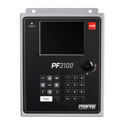
ProFire PF3100 Series User manual

Product Manual
DOC-001149 v8.0

PF3100 Product Manual
DOC-001149 v8.0
Copyright © 2022, Profire Energy. All rights reserved.
855.PRO.FIRE | solutions@profireenergy.com
CONTENTS
1IMPORTANT SAFETY INFORMATION ....................4
2DOCUMENT SCOPE....................................................5
2.1 Additional Documentation .................................5
3APPROVALS AND RATINGS.....................................6
3.1 Certifications.........................................................6
3.2 Product Declarations...........................................7
3.3 Product Specifications.........................................7
3.4 Enclosure Specifications .....................................8
4PF3100-00 USER INTERFACE CARD.........................9
4.1 Terminal Ratings ..................................................9
4.2 Keypad................................................................ 10
4.3 User Interface Display ...................................... 11
4.4 Status LED .......................................................... 15
4.5 PFRN Controller Network Port ........................ 16
4.6 USB Port ............................................................. 17
4.7 SD Card Slot....................................................... 17
4.8 Battery ................................................................ 17
5PF3101-00 BMS CONTROLLER CARD....................18
5.1 Terminal Ratings ............................................... 19
5.2 Controller Power Input..................................... 20
5.3 Status Contact ................................................... 21
5.4 High Fire Valve Solenoid Output..................... 22
5.5 Main Valve Solenoid Output 2......................... 23
5.6 Main Valve Solenoid Output 1......................... 24
5.7 Pilot Valve Solenoid Output............................. 25
5.8 Auxiliary 4-20mA Output ................................. 26
5.9 Remote Start Input ........................................... 28
5.10 Proof of Closure Input...................................... 29
5.11 Auxiliary Input ................................................... 30
5.12 Emergency Shutdown Input ............................ 33
5.13 Fuel Pressure Input........................................... 34
5.14 Level/Flow Input................................................ 36
5.15 PFRN Controller Network................................. 38
5.16 PFRN I/O Network............................................. 39
5.17 External Ignition Switch Input ......................... 41
5.18 BMS Front Panel LED Output .......................... 42
6PF3102-00 ION PILOT CARD....................................43
6.1 Terminal Ratings ............................................... 43
6.2 Ion Auxiliary Input............................................. 44
6.3 Ion Pilot Valve Output ...................................... 45
6.4 Main Ionization Flame Detection Input ..........46
6.5 Pilot Ionization Flame Detection Input ...........46
6.6 Pilot Ignition Coil Output ..................................48
6.7 PFRN Port............................................................49
7PF3102-01 UV PILOT CARD......................................50
7.1 Terminal Ratings ................................................50
7.2 Ignition Enable Relay Contact ..........................51
7.3 Required UV Flame Scanner Inputs ................52
7.4 UV Flame Scanner Flame Strength Input .......53
7.5 PFRN Port............................................................54
7.6 Dip Switches .......................................................55
7.7 Power Setting LEDs............................................55
8PF3102-03 PILOT SPARK CARD ..............................56
8.1 Terminal Ratings ................................................56
8.2 Power Input ........................................................57
8.3 Coil Enable Input................................................57
8.4 Coil Ignition Output ...........................................57
9PF3103-00 TEMPERATURE CARD...........................58
9.1 Terminal Ratings ................................................58
9.2 Thermocouple Inputs........................................59
9.3 PFRN Port............................................................61
10 PF3106-00 NETWORK CARD....................................62
10.1 Terminal Ratings ................................................62
10.2 Power Input ........................................................63
10.3 PFRN Ports..........................................................64
11 PF3107-00 MODBUS CARD......................................65
11.1 Terminal Ratings ................................................65
11.2 Power Input ........................................................66
11.3 Start Input...........................................................67
11.4 Status Output .....................................................67
11.5 Modbus Connection ..........................................68
11.6 PFRN Ports..........................................................69
12 PF3113-00 I/O EXPANSION CARD..........................70
12.1 Terminal Ratings ................................................70
12.2 Normally Closed Dry Contact...........................71
12.3 Normally Open Dry Contact .............................72
12.4 4-20 mA Output .................................................73
12.5 Configurable I/O Expansion Inputs .................76
12.6 PFRN Port............................................................83

PF3100 Product Manual
DOC-001149 v8.0
Copyright © 2022, Profire Energy. All rights reserved.
855.PRO.FIRE | solutions@profireenergy.com
13 OPERATING SEQUENCE ..........................................84
13.1 Power On State ................................................. 85
13.2 Alarm State ........................................................ 86
13.3 Ready State ........................................................ 87
13.4 Lockout State..................................................... 88
13.5 Waiting State...................................................... 89
13.6 Startup Checks State ........................................ 92
13.7 Proven Pre-Purge Sequence............................ 93
13.8 Ignition State...................................................... 97
13.9 Pilot State ........................................................... 98
13.10 Low Fire State.................................................. 101
13.11 Process Control States ................................... 103
14 INSTALLATION........................................................107
14.1 Mounting Considerations .............................. 107
14.2 Hardware Installation Diagrams................... 109
14.3 Connection Diagrams..................................... 110
15 SYSTEM CONFIGURATION...................................123
15.1 Appliance ......................................................... 123
15.2 BMS Controller ................................................ 123
15.3 I/O Card ............................................................ 123
15.4 Modbus Card ................................................... 123
15.5 Network Card .................................................. 123
15.6 Communication............................................... 123
15.7 Card Identification .......................................... 123
15.8 System Scaling................................................. 124
16 COMMISSIONING...................................................125
16.1 Passwords........................................................ 125
16.2 Update Firmware ............................................ 125
16.3 User Interface Settings................................... 126
16.4 Appliance Wizard ............................................ 127
16.5 Temperature Wizard ...................................... 128
16.6 Pilot Wizard...................................................... 131
16.7 I/O Expansion Wizard ..................................... 133
16.8 Output Calibration Wizard............................. 136
16.9 FARC/O2Trim Wizard...................................... 137
16.10 BMS Controller Settings ................................. 142
16.11 FARC Tuning Settings...................................... 160
16.12 O2 Trim Tuning................................................. 161
16.13 Test System...................................................... 162
16.14 Save Settings.................................................... 162
17 SYSTEM OPERATION.............................................163
17.1 Starting the System ........................................ 163
17.2 Accessing System Status Information.......... 164
17.3 Adjusting Setpoints......................................... 164
17.4 Adjusting Input and Output Settings ........... 164
17.5 Stopping the System ...................................... 165
17.6 Reigniting a Lost Pilot..................................... 166
17.7 Acknowledging Lockouts ............................... 166
17.8 Advanced PF3100 Software Features .......... 167
18 SOFTWARE UTILITIES............................................169
18.1 Quick Start Setup Tool ................................... 169
18.2 Swap Wizard.................................................... 169
18.3 Diagnostics ...................................................... 172
18.4 Logging............................................................. 173
18.5 Settings............................................................. 175
18.6 Firmware.......................................................... 177
19 MAINTENANCE.......................................................179
19.1 Tools Required ................................................ 179
19.2 Regular Maintenance Recommendations ... 179
19.3 Repair and Replacement ............................... 179
19.4 Decommissioning ........................................... 179
19.5 Manufacturer Notification............................. 179
20 ALERT CODES ..........................................................180
20.1 Alarms .............................................................. 180
20.2 Waits................................................................. 190
20.3 Warnings .......................................................... 192
20.4 Main Permissives............................................ 195
21 GLOSSARY................................................................197
21.1 Terms ............................................................... 197
21.2 Acronyms ......................................................... 197
22 DOCUMENT REVISION HISTORY.........................198
22.1 Hardware and Firmware Versions................ 198
22.2 Document Change Summary........................ 198

PF3100 Product Manual
DOC-001149 v8.0
Copyright © 2022, Profire Energy. All rights reserved.
855.PRO.FIRE | PROFIREENERGY.COM
4
1IMPORTANT SAFETY INFORMATION
Warning: All PF3100 installations must follow the installation, commissioning, operation and
maintenance procedures outlined in this manual. Failure to comply with the instructions and warnings
in this manual may result in death, serious injury, electrocution, property damage, product damage
and
/or government fines. All PF3100 installations must be performed in accordance with local
electrical code(s) by a capable electrician and
must be field inspected by the Authority Having
Jurisdiction to ensure compliance with local electrical and gas codes.
Warning: Do not disconnect power, open enclosures, or otherwise service the product unless area is
known to be non-hazardous.
Warning: Do not remove or replace fuses
when system is powered. Replacement fuses must be
ceramic and of correct rating. Contact Profire for replacement fuses.
Warning: All safety functions being used must be end-to-end proven following commissioning of the
system.
Warning: Ignition coils can generate 20 kV - 40 kV at their high voltage output terminals and can cause
cardiac arrest. Do not touch or place any object near the ignition coil or connected ignition wire while
the product is operating. It is possible to draw a spark from several inches away if the pilot bracket is
not properly grounded.
Warning: Do not bypass any of the safety functions or modify any of the internal circuitry of the system.
Doing so can lead to death, serious injury, electrocution, property damage, product damage and/or
government fines.
!
!
!
!
!
!

PF3100 Product Manual
DOC-001149 v8.0
Copyright © 2022, Profire Energy. All rights reserved.
855.PRO.FIRE | PROFIREENERGY.COM
5
2DOCUMENT SCOPE
The Profire PF3100 is a modular combustion control system that can be customized and scaled to monitor and
control a wide variety of industrial heating applications. The system is designed to ensure safe burner ignition and
reliable process temperature control while supporting applications requiring ionization and/or UV flame detection,
peripheral input device monitoring, fuel-air ratio control and oxygen trim. Configuration of the system is performed
through the user interface module which also provides real-time status, state and alert information.
This document outlines the information required to design, commission, install and maintain a PF3100 system.
Included are the ratings and input/output capabilities of each PF3100 card, the PF3100 system states and operating
sequence, Installation instruction and diagrams, commissioning and maintenance procedures and additional
information pertaining to use and functionality of a PF3100 system.
The information contained in this document applies to PF3100 cards with the hardware and firmware versions listed
below:
PF3100 Card Hardware Version Firmware Version
PF3100-00 UI Card v1.3.x NA-43.3
PF3101-00 BMS Controller Card v1.3.x NA-43.3
PF3102-00 Ion Pilot Card v2.2.x NA-43.3
PF3102-01 UV Pilot Card v1.0.x NA-43.3
PF3102-03 Pilot Spark Card v1.1.x Not applicable
PF3103-00 Temperature Card v1.4.x NA-43.3
PF3106-00 Network Card v2.1.x Not applicable
PF3107-00 Modbus Card v1.3.x NA-43.3
PF3113-00 I/O Expansion Card v2.0.x NA-43.3
The hardware version is printed on the bottom line of the serial number label affixed to each card, while the
firmware version can be found using the Network Discovery tool (System Screen > Config Tab > Diagnostics). Note
that all connected cards must be running the same version of firmware for the system to operate correctly.
2.1 ADDITIONAL DOCUMENTATION
Visit the Profire Documentation Website for additional PF3100 documents, or to access archived documentation.
Contact Profire for Appendix A: Functional Safety design for additional functional safety information required for
IEC 61511 analysis.

PF3100 Product Manual
DOC-001149 v8.0
Copyright © 2022, Profire Energy. All rights reserved.
855.PRO.FIRE | PROFIREENERGY.COM
6
3APPROVALS AND RATINGS
3.1 CERTIFICATIONS
The following matrix identifies the PF3100 equipment and cards that make up each model, as well as the applicable
certifications for each.
Model Enclosure Type PF3100 Hardware Certifications
UIX Enclosure
CTX Enclosure
AUX Enclosure
EPX Enclosure
TLX Enclosure
PF3100
-00 UI Card
PF3101
-
00 BMS Controller Card
PF3102
-
00 Ion Pilot Card
PF3102
-
01 UV Pilot Card
PF3102
-
03 Pilot Spark Card
PF3103
-
00 Temperature Card
PF3106
-
00 Network Switch Card
PF3107
-
00 Modbus Comm Card
PF3113
-00 I/
O Expansion Card
IEC 61508: 2010 Parts 1
-7 (SIL 2)
UL 60730
-2-5:2014 Ed.3
CSA C22.2#60730
-2-5 :2014 Ed.1
ANSI Z21.20:2014 Ed.1
UL 61010
-
1:2012 Ed.3+R:29Apr2016
CSA C22.2#61010
-1-12:2012 Ed.3
Class I, Div. 2, GRP ABCD; T4
Class I,
Div. 1, GRP BCD; T4
Class I, Div. 1, GRP BCD, T6, IP66, 4X
Class I,
Zone 1 AExd IIB+H2 T6 Gb, IP66
Ex d IIB+H2 T6 Gb, IP66
(Note 5)
(Note 6)
(Note 7)
(Note 8)
PF3100-00
•
•
•
1
PF3100-00A
•
•
•
• 1
•
PF3100-00B
•
•
•
•
• 1
•
PF3100-00C
•
•
•
•
• 2
•
PF3100-00D
•
•
•
•
•
• 2
•
PF3100-00E
•
•
•
•
•
•
•
PF3100-00J
•
•
•
•
• 1
•
PF3100-00K
•
•
•
•
•
• 2
•
PF3100-00T
•
•
•
•
•
• 1
•
PF3100-00U
•
•
•
•
•
• 2
•
PF3101-00
•
•
•
2
PF3101-00A
•
•
•
• 2
•
PF3101-00B
•
•
•
•
• 2
•
PF3102-00
•
•
• 3
PF3102-00A
•
•
•
• 3
•
PF3102-01
•
•
•
4
•
9
PF3102-03
•
•
• 4
• 9
PF3103-00
•
•
• 1
PF3103-00D
•
•
•
•
1
•
PF3106-00
•
•
• 1
PF3106-00A
•
•
•
•
1
•
PF3107-00
•
•
• 1
PF3107-00A
•
•
•
• 1
•
PF3113-00
•
•
• 4
• 9
1 must be installed with a PF3101-00x card/module and a PF3102-00x card/module to maintain compliance.
2 must be installed with a PF3102-00x Ion Pilot card/module to maintain compliance.
3must be installed with a PF3101-00x BMS Controller card/module to maintain compliance.
4Evaluation must be conducted following installation to verify compliance.
5Refer to Appendix A: Functional Safety Design for details - available upon request.
6 In accordance with ISA 12.12.01:2015 Ed.6 • CSA C22.2#213:2016 Ed.2
7In accordance with ISA 12.12.01:2015 Ed.6 • CSA C22.2#213:2016 Ed.2 • CSA C22.2#30:1986 Ed.3+G1;G2 • UL 1203:2013 Ed.5 +R:16Oct2018
8In accordance with ANSI/ISA 60079-1:091 • ANSI/UL 1203 – 2013 • CAN/CSA-C22.2 No. 60079-1:11
9Certified as a recognized component.

PF3100 Product Manual
DOC-001149 v8.0
Copyright © 2022, Profire Energy. All rights reserved.
855.PRO.FIRE | PROFIREENERGY.COM
7
3.2 PRODUCT DECLARATIONS
System Parameter Declared Value
Maximum Ionization Flame Failure Lock-Out Time 4 seconds
Maximum UV Flame Failure Lock-Out Time 4 seconds
Maximum Ignition Time 10 seconds
Maximum Pilot-Flame Establishing Period 10 seconds
Maximum Main-Flame Establishing Period 10 seconds
Minimum Pre-Purge Time 10 seconds
Minimum Post-Purge Time 10 seconds
Minimum Recycle Time 10 seconds
Maximum Start-up Lock-Out Time 10 seconds
Maximum Number of Start-up Retries 3
Maximum number of BMS Controller cards per UI card 16
Maximum number of BMS Controller cards per appliance 16
Maximum number of Pilot cards per BMS Controller card 4
Maximum number of Temperature cards per BMS Controller card
5
Maximum number of IO Expansion cards per BMS Controller card 5
Maximum number of Temperature inputs per appliance 20
Maximum number of I/O Expansion inputs per appliance 45
3.3 PRODUCT SPECIFICATIONS
System Parameter Rating
12V Mode 24V Mode
Voltage Range 10.2 to 16.2 VDC 20.4 to 32.4 VDC
PF3100-00 UI Card Power Consumption (with USB) 5.5 W 5.5 W
PF3101-00 BMS Card Power Consumption (with LED board) 2.1 W 2.6 W
PF3102-00 Ion Pilot Card Power Consumption 1.7 W 1.8 W
PF3102-01 UV Pilot Card Power Consumption 1.1 W 1.0 W
PF3102-03 Pilot Spark Card Power Consumption (Peak while sparking) 2.1 W 11.9 W
PF3103-00 Temperature Card Power Consumption 1.0 W 1.0 W
PF3106-00 Network Card Power Consumption 0.6 W 0.6 W
PF3107-00 Modbus Card Power Consumption 1.3 W 1.3 W
PF3113-00 I/O Expansion Card Power Consumption 1.2 W 1.4 W
Operating and Storage Temperature -40°C to 55°C (-40°F to 131°F)
PF3100 Electromagnetic Field Immunity has been verified in accordance with IEC 61000-4-3:2010 and IEC 61000-4-6:2010.

PF3100 Product Manual
DOC-001149 v8.0
Copyright © 2022, Profire Energy. All rights reserved.
855.PRO.FIRE | PROFIREENERGY.COM
8
3.4 ENCLOSURE SPECIFICATIONS
UIX/CTX/AUX Enclosure EPX Enclosure TLX Enclosure
Material Polyester painted steel Aluminum Aluminum
Conduit Entry
UIX, CTX and AUX:
4 x ¾” pre-cut, bottom entry
4 x ½” pre-cut, bottom entry
UIX and CTX only:
1 x ½” keyed, pre-cut, side entry
4 x ¾” NPT 3 x ¾” NPT
1 x ½” NPT
Mounting Channel bar or direct mount Channel bar or direct mount
½” NPT thermowell
Type 4 4X 4X
Ingress Protection IP66 IP66 IP66
Operating/Storage
Temperature
-40°C to 55°C
(-40°F to 131°F)
-40°C to 60°C
(-40°F to 140°F)
-40°C to 55°C
(-40°F to 131°F)
3.4.1 ENCLOSURE DIMENSIONS
UIX/CTX/AUX EPX TLX
5.20" 12.19"
11.32"
6.50"
8.36"
8.97"
3/8" Ø
1" Ø
¾” Ø
8.53"2.39"
6.00"
6.63"
0.50"
0.28"
¾” NPT
6.00"
4.00"
½” NPT
5.00"
¾” NPT
15/32” Ø

PF3100 Product Manual
DOC-001149 v8.0
Copyright © 2022, Profire Energy. All rights reserved.
855.PRO.FIRE | PROFIREENERGY.COM
9
4PF3100-00 USER INTERFACE CARD
The PF3100 User Interface card is the primary access point for commissioning and monitoring the PF3100
system. It consists of a 5.7” color display and a full keypad for navigation and configuration, as well as an appliance
status LED indicator and a USB port for data logging and settings file management.
STATUS
PF
3100
PWR
12345678
LINK
Data Logging
Reset
CR20 32 Boot
Ex t B at t
+-
PF3100-00
XX :00: 00 :0 0: XX :X X
139750
2021-12-31
v1.3.x
4.1 TERMINAL RATINGS
Name Safety Rated Input/Output Electrical Ratings
PFRN Controller Network Yes I/O Power consumer: 36 VDC, 1A maximum
USB Port No I/O 5V, 500mA maximum
SD Card Port No I/O N/A
Battery No I 3V, 225mAh
Keypad No I N/A

PF3100 Product Manual
DOC-001149 v8.0
Copyright © 2022, Profire Energy. All rights reserved.
855.PRO.FIRE | PROFIREENERGY.COM
10
PWR
12345678
LINK
Data Logging
Reset
CR2032 Boot
Ex t Bat t
+-
PF3100-00
XX: 00: 00 :0 0: XX :X X
139750
2021-12-31
v1.3.x
STATUS
PF
3100
4.2 KEYPAD
4.2.1 DETAILS
Terminals 14-pin connector on bottom of UI card
4.2.2 KEYPAD FUNCTIONALITY
Button Description
Stop a single controller 1
Stop a single appliance
1
Stop all appliances
1
Return to previous screen
Bring up Appliance Quick Adjust menu
Bring up Flame Diagnostics menu from the Controller Status screen
Bring up multi-controller settings menu while adjusting settings
Save a screenshot to a connected USB storage device (hold down)
Toggles between Table and Graph view when configuring FARC channels.
Select a highlighted item
Displays configuration options of password protected drop-down settings.
Make incremental changes to numeric settings
Make incremental changes on Quick Adjust menu
Scroll full pages of information (Event log, Controller Status Screen, etc.)
Navigate menus and highlight items
Start a single controller from the Ready state
Start a single appliance when all associated controllers are in the Ready state
Start all appliances when all controllers are in the Ready state
Change numeric settings
Delete key can also be used to unassign items in the configuration wizards.
1The keypad is intended to aid in commissioning and system navigation and must not be incorporated into any safety function. If user shutdown is a required
safety function, then the BMS Controller card ESD input(s) or external ignition switch(es) must be used.

PF3100 Product Manual
DOC-001149 v8.0
Copyright © 2022, Profire Energy. All rights reserved.
855.PRO.FIRE | PROFIREENERGY.COM
11
STATUS
PF
3100
4.3 USER INTERFACE DISPLAY
4.3.1 DETAILS
Type Transmissive color TFT-LCD
Size 5.7”
Resolution 640 x 480
4.3.2 PF3100 STATUS AND CONFIGURATION SCREENS
Screen Name Screenshot Navigation Description
System Screen -
Status Tab
Press repeatedly from
any screen.
Displays all the configured
appliances as well as their
current state and process
temperature.
System Screen -
Config Tab
From the System Status Tab,
press .
press to highlight desired
option, then press to
launch.
Provides access to
configuration wizards, system
diagnostics, data logging
tools, settings file
management utilities and a
firmware update tool.
Appliance Screen -
Status Tab
From System Status Tab,
press to highlight desired
appliance, then press .
Displays the temperature
readings, input readings and
output signals for the selected
appliance as well as the
current state of every BMS
controller in the appliance.

PF3100 Product Manual
DOC-001149 v8.0
Copyright © 2022, Profire Energy. All rights reserved.
855.PRO.FIRE | PROFIREENERGY.COM
12
Screen Name Screenshot Navigation Description
Controller Status
Screen
From Appliance Status Tab,
press and to highlight
desired controller, then
press .
Displays detailed information
for all inputs and outputs of
the selected controller and
connected cards.
Flame Diagnostics
Screen
From Controller Status
Screen, press .
Displays flame strength
readings for each Pilot card.
Green indicates a strong
flame, orange indicates a
weak flame and red indicates
a poor flame.
Appliance Screen -
Alerts Tab
From Appliance Status Tab,
press .
Displays all active alerts
(alarms, waits, warnings and
main permissives) for the
appliance. Pressing on an
alert displays additional
troubleshooting details if
available.

PF3100 Product Manual
DOC-001149 v8.0
Copyright © 2022, Profire Energy. All rights reserved.
855.PRO.FIRE | PROFIREENERGY.COM
13
Screen Name Screenshot Navigation Description
Appliance Screen -
Settings Tab
From Appliance Alerts Tab,
press .
Contains configuration
settings for all controllers in
the appliance.
Appliance Screen -
FARC Settings
Dialog
From Appliance Status Tab,
press and to highlight
“FARC” option *, then press
.Use to toggle
between Table View and
Curve View.
* This option is only visible
when the FARC Enable
setting (FARC/O2Trim
Wizard > General Tab) is
set to Enabled
Contains FARC table and
additional tuning settings.
Appliance Screen -
O2 Trim Settings
Dialog
From Appliance Status Tab,
press and to highlight
“O2Trim” option *, then
press .Use to cycle
through Table and Graph
views.
* This option is only visible
when the Trim Channel
(FARC/O2Trim Wizard > O2
Trim Tab) is not set to
Disabled
Contains O2Trim tables and
additional tuning settings.

PF3100 Product Manual
DOC-001149 v8.0
Copyright © 2022, Profire Energy. All rights reserved.
855.PRO.FIRE | PROFIREENERGY.COM
14
Screen Name Screenshot Navigation Description
Quick Adjust Dialog
From System Screen or
Appliance Screen, press .
Allows for quick adjustment of
the appliance Process
Setpoint. Use and to
make incremental
adjustments.
Lockout Screen
N/A – Lockout Screen
appears automatically upon
controller lockout.
Displays important shutdown
information upon a controller
lockout. The screen persists
until it is acknowledged by a
user.
UI Boot Menu
From Power Off, press and
hold while powering up
the UI.
* It may take up to 30
seconds for the Boot Menu
to appear.
Provides access to useful
troubleshooting tools as well
as utilities for updating the UI
operating system. Contact
Profire for instructions on
how and when to use the
Boot Menu utilities.

PF3100 Product Manual
DOC-001149 v8.0
Copyright © 2022, Profire Energy. All rights reserved.
855.PRO.FIRE | PROFIREENERGY.COM
15
STATUS
PF
3100
4.4 STATUS LED
4.4.1 DETAILS
Color Green/Amber/Red
Indication Appliance Run Status
4.4.2 SYSTEM BEHAVIOR
Scenario LED Color LED Behavior
All appliances are stopped Red Solid
All appliances are running Green Solid
Some appliances are running and one or more are stopped Green Blinking
Status LED is malfunctioning
Contact Profire Amber Any

PF3100 Product Manual
DOC-001149 v8.0
Copyright © 2022, Profire Energy. All rights reserved.
855.PRO.FIRE | PROFIREENERGY.COM
16
PWR
12345678
LINK
Data Logging
Reset
CR2032 Boot
Ex t Bat t
+-
PF3100-00
XX: 00: 00 :0 0: XX :X X
139750
2021-12-31
v1.3.x
4.5 PFRN CONTROLLER NETWORK PORT
4.5.1 DETAILS
PFRN Class Interface
Type Power consuming PFRN port
Connector type 8P8C
4.5.2 INTENDED FIELD DEVICE CONNECTIONS
Field Device Configuration Requirements Connection Diagrams
PF3101-00 BMS Controller card
N/A 8P8C PFRN Connector Wiring
UI PFRN Connector Options
PF3101-00 BMS Controller card
via PF3106-00 Network card
PF3101-00 BMS Controller card
via PF3107-00 Modbus card
4.5.3 LED BEHAVIOR
Name Color LED Behavior Interpretation Corrective Action
Pwr Blue
Off Port has no power
Make sure connected power producer card (BMS
controller card, Network card, Modbus card) is
powered on.
Check PFRN wire terminations
On – Solid Port has power N/A
On – Flickering Port has intermittent power Check PFRN wire terminations
Link Green
Off Port is not communicating Check PFRN wire terminations
On – Solid
Port is communicating normally N/A
On – Flickering

PF3100 Product Manual
DOC-001149 v8.0
Copyright © 2022, Profire Energy. All rights reserved.
855.PRO.FIRE | PROFIREENERGY.COM
17
PWR
12345678
LINK
Data Logging
Reset
CR2032 Boot
Ex t Bat t
+-
PF3100-00
XX: 00: 00 :0 0: XX :X X
139750
2021-12-31
v1.3.x
PWR
12345678
LINK
Data Logging
Reset
CR2032 Boot
Ex t Bat t
+-
PF3100-00
XX: 00: 00 :0 0: XX :X X
139750
2021-12-31
v1.3.x
PWR
12345678
LINK
Data Logging
Reset
CR2032 Boot
Ex t Bat t
+-
PF3100-00
XX: 00: 00 :0 0: XX :X X
139750
2021-12-31
v1.3.x
4.6 USB PORT
Warning: Do not remove or install a USB stick unless the area is
known to be non-hazardous.
4.6.1 DETAILS
Recommended Capacity 1 GB
Recommended Operating Rating -40°C – 60°C (-40°F – 140°F)
4.6.2 USB FUNCTIONALITY
Function Procedure
Save controller settings to USB drive Use the Backup tool to save settings to a USB drive.
Load controller settings from USB drive Use the Restore tool to load settings to a USB drive.
Update card firmware Use the Firmware Update tool to modify the firmware of a connected card.
Export event log Use the Event Logging and Export tools to view and save system events.
Export data log Use the Data Logging and Export tools to trend and save system data.
4.7 SD CARD SLOT
Warning: Do not remove or install the SD card unless the area is
known to be non-hazardous.
4.7.1 DETAILS
Recommended Size Standard or mini/micro with adapter
Recommended Capacity 8GB
4.7.2 SD CARD FUNCTIONALITY
Function Procedure
Update UI operating system (PFnix)
UI Boot Menu > Update PFnix
Contact Profire for approved PFnix update file and update procedure.
* This is different than a firmware update. For UI firmware update procedure
refer to Firmware Update section.
4.8 BATTERY
Do not remove or install the battery unless the area is known to be
non-hazardous.
4.8.1 DETAILS
Voltage 3V
Type CR 2032
!
!
!

PF3100 Product Manual
DOC-001149 v8.0
Copyright © 2022, Profire Energy. All rights reserved.
855.PRO.FIRE | PROFIREENERGY.COM
18
5PF3101-00 BMS CONTROLLER CARD
The BMS Controller card is the dedicated hub for all I/O cards and instrumentation associated with a specific burner
in an appliance. All inputs are monitored by the BMS to identify shutdown conditions and to determine safety
output behavior and state transitions.
STATUS
PF
3100
BMS CONTROL MODULE
MAIN
PILOT
IGNITING
12-24 VDC
Common
Ea rth GN D
HFV-
HFV+
SSV2+
SSV2-
SSV1+
SSV1-
Pilot+
Pilot-
Aux Out-
Aux Out+
Start-
Start+
ESD-
ESD+
POC-
POC+
Aux In-
Aux In+
Pressure-
Pressure+
Level-
Level+
4-20mA / Dry
Contact Inputs
Dry Contact Inputs Powered Outputs Relay Output
Power Input4-20mA 12/24V
STATUS
SPST
NO
80mA
120 VAC/
120 VDC
MAX
-
-
-
-
-
-
-
-
-
-
-
-
-
-
-
-
-
-
-
-
-
-
-
-
-
-
-
1
2
3
6
7
9
8
11
10
13
12
14
15
16
17
22
23
18
19
20
21
24
25
26
27
5
4
PF3101-00
XX : 00: 00 :0 0:XX :X X
139750
2021-12-31
v1.3.x
PF3101-00
BMS Cont rol ler
V1.3
Run Ignite On
PFRN IO Network
PFRN Controller Network
33 – Ignition
Switch
35 – License Key
34 - Keypad
Push Tabs
To Rem ove Key
Spare Fuse
10A
Fuse
123679 811 1013 12141516172223 1819202124252627 5 4

PF3100 Product Manual
DOC-001149 v8.0
Copyright © 2022, Profire Energy. All rights reserved.
855.PRO.FIRE | PROFIREENERGY.COM
19
5.1 TERMINAL RATINGS
Name Safety
Rated Terminal Input/Output Electrical Ratings
Power Input No
1
12-24 VDC
I 12-24 VDC
10A maximum
*Fused at 10A
2
Common
3
Earth GND
GND
Relay Output No
4
STATUS A
-
Dry contact
120 VAC/VDC
80mA maximum
5 STATUS B
HFV No
6
-
O
12-24 VDC
2A maximum
Pulsed Output with configurable PWM
Expected Load: Inductive/Resistive
7
+
SSV2 Yes 8 - O
9
+
SSV1 Yes
10
-
O
11
+
Pilot Yes 12 - O
13
+
Aux Out No
14 -
O
12-24 V
DC
20mA maximum
Maximum output device impedance:
12V Mode: 250Ω, 24V Mode: 900Ω
15 +
Start Yes 16 - I 30 VDC max, 2mA minimum wetting current
17
+
O
12-24 V
DC
, 100mA maximum
1
POC Yes
18
-
I
30 VDC max, 2mA minimum wetting current
19
+
O
12-24 V
DC
, 100mA maximum 1
Aux In Yes
20
-
I
30 V
DC
max, 2mA minimum wetting current
21
+
O
12-24 V
DC
, 100mA maximum
1
ESD Yes
22
-
I
30 VDC max, 2mA minimum wetting current
23
+
O
12-24 V
DC
, 100mA maximum 1
Pressure Yes 24 - I
Digital Mode: 30 V
DC
max, 2mA minimum wetting current
4-20 Mode: 30 VDC max, 25mA maximum
Input resistance ~200Ω
25
+
O
12-24 VDC, 50mA maximum,
Level Yes 26 - I
Digital Mode: 30 V
DC
max, 2mA minimum wetting current
4-20 Mode: 30 VDC max, 25mA maximum
Input resistance ~200Ω
27
+
O
12-24 V
DC
, 50mA maximum,
PFRN
Controller
Network
Yes 28 I/O 36 VDC
1A maximum
PFRN I/O
Network Yes
29 I/O
36 VDC
1A maximum
30
I/O
31
I/O
32
I/O
Ignition Switch
Yes 33
Run I 3.3 VDC
Ignite
I
On
O
3.3 VDC
Keypad
No
34
O
3.3 V
DC
License Key No 35 I 3.3 VDC
1The combined current requirements of the Start, POC, Aux In and ESD input devices cannot exceed 100mA.

PF3100 Product Manual
DOC-001149 v8.0
Copyright © 2022, Profire Energy. All rights reserved.
855.PRO.FIRE | PROFIREENERGY.COM
20
12-24 VDC
Common
Ea rth GN D
HFV-
HF V+
SSV2+
SSV2-
SSV1+
SSV1-
Pilot+
Pilot-
Aux Out-
Aux Out+
Start-
Start+
ESD-
ESD +
POC-
POC+
Aux In-
Aux In+
Pressure-
Pressure+
Leve l-
Leve l+
4-20mA / D ry
Contact Inputs
Dry Contact Input s Po wered O utputs Relay Output
Power Input
4-20mA 12/24V
STATUS
SPST
NO
80m A
120VAC/
120VDC
MAX
-
-
-
-
-
-
-
-
-
-
-
-
-
-
-
-
-
-
-
-
-
-
-
-
-
-
-
1
2
3
6
7
9
8
11
10
13
12
14
15
16
17
22
23
18
19
20
21
24
25
26
27
5
4
PF3101-00
XX:00:00:00:XX:XX
#### ##
YYYY-MM-DD
V# .#. #
PF3101-00
BMS C ont r ol ler
V1.3
RunIgniteOn
PFRN IO Ne twork
PFRN Contr oller Network
33 – Ignition
Switch
35 – License Key
34 - Keypad
Push Ta bs
To Remove Key
Spare Fuse
10A
Fuse
123679 811 1013 12141516172223 1819202124252627 5 4
5.2 CONTROLLER POWER INPUT
5.2.1 DETAILS
Terminals
1, 2 & 3
Name
Power Input
Type
BMS power input
Fuse
10A ceramic, Contact Profire for replacements
5.2.2 INTENDED FIELD DEVICE CONNECTIONS
Field Device Configuration Requirements Connection Diagrams
12V Power Supply
Controller Settings > Setup > System Voltage
Controller Voltage: 12V
Voltage Restart: As desired Power Input Wiring
24V Power Supply
Controller Settings > Setup > System Voltage
Controller Voltage: 24V
Voltage Restart: As desired
5.2.3 VOLTAGE ALERT BEHAVIOR – 12V MODE
Scenario State
Transition Controller Alerts
System Voltage Low Voltage
Restart
High Voltage
Restart Controller State
Below 9.6V *
Enabled Any
Any running state
Waiting
Low Voltage Wait
Any stopped state
No effect
Low Voltage Wait
Disabled Any
Any running state
Lockout
Low Voltage Alarm
Any stopped state
Alarm
Low Voltage Alarm
Between 9.6V and 9.9V *
Any
Any
Any
No effect
Low Voltage Warning
Between 9.9V and 16.1V *
Any
Any
Any
No effect
N/A
Between 16.1V and 16.8V *
Any
Any
Any
No effect
High Voltage Warning
Above 16.8V *
Any Enabled
Any running state
Waiting
High Voltage Wait
Any stopped state
No effect
High Voltage Wait
Any Disabled
Any running state
Lockout
High Voltage Alarm
Any stopped state
Alarm
High Voltage Alarm
* All listed voltage thresholds are +/- 1.0 V
5.2.4 VOLTAGE ALERT BEHAVIOR – 24V MODE
Scenario State
Transition Controller Alerts
System Voltage Low Voltage
Restart
High Voltage
Restart Controller State
Below 19.2V *
Enabled Any
Any running state
Waiting
Low Voltage Wait
Any stopped state
No effect
Low Voltage Wait
Disabled Any
Any running state
Lockout
Low Voltage Alarm
Any stopped state
Alarm
Low Voltage Alarm
Between 19.2V and 19.9V *
Any
Any
Any
No effect
Low Voltage Warning
Between 19.9V and 33.1V *
Any
Any
Any
No effect
N/A
Between 33.1V and 33.6V *
Any
Any
Any
No effect
High Voltage Warning
Above 33.6V *
Any Enabled
Any running state
Waiting
High Voltage Wait
Any stopped state
No effect
High Voltage Wait
Any Disabled
Any running state
Lockout
High Voltage Alarm
Any stopped state
Alarm
High Voltage Alarm
* All listed voltage thresholds are +/- 1.0 V
Other manuals for PF3100 Series
6
Table of contents
Other ProFire Control System manuals
