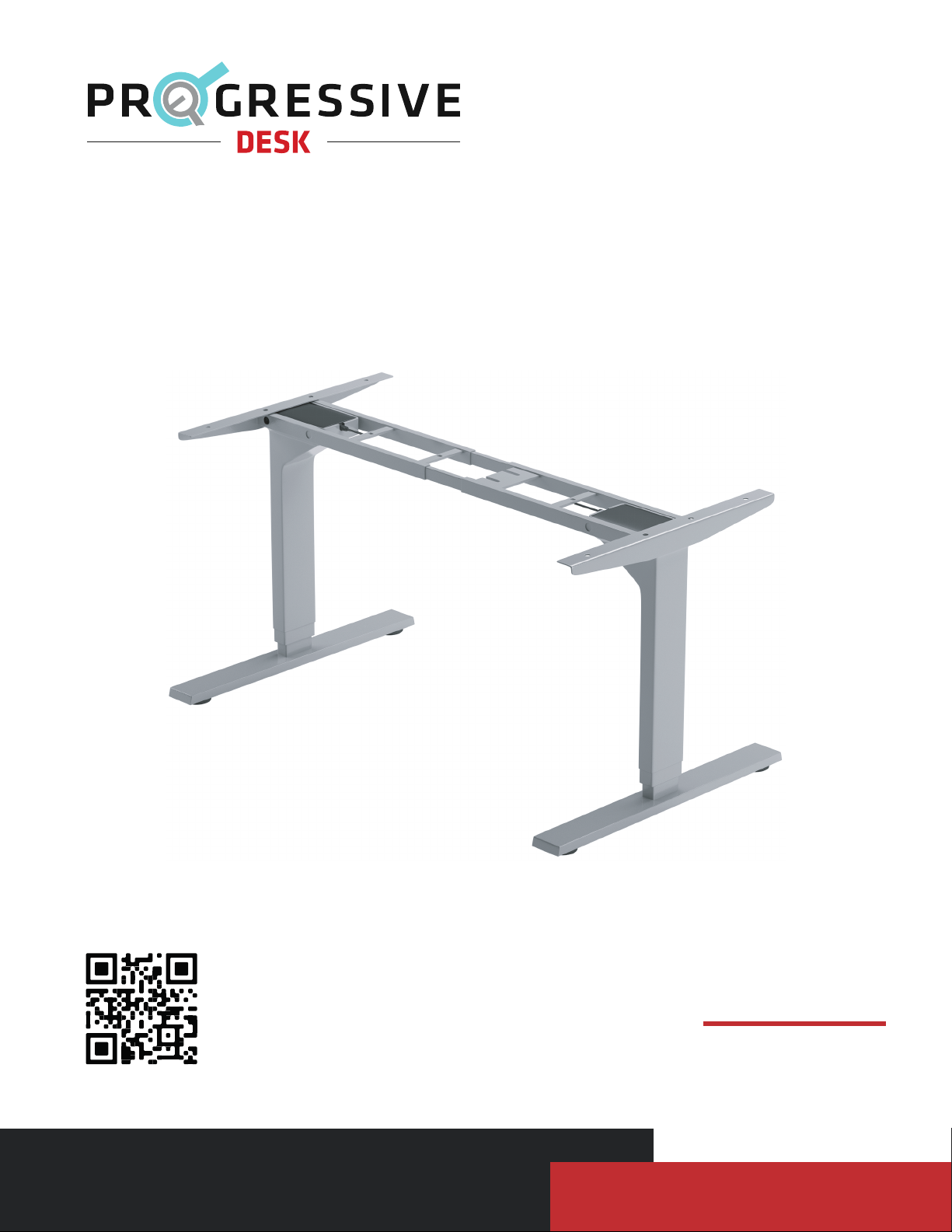
PROGRESSIVE DESK FLT-02 User manual


Other manuals for FLT-02
1
Table of contents
Other PROGRESSIVE DESK Indoor Furnishing manuals

PROGRESSIVE DESK
PROGRESSIVE DESK FLT-01 User manual

PROGRESSIVE DESK
PROGRESSIVE DESK ST-01 User manual

PROGRESSIVE DESK
PROGRESSIVE DESK Corner Ryzer FLT-05 User manual

PROGRESSIVE DESK
PROGRESSIVE DESK ST-03 User manual

PROGRESSIVE DESK
PROGRESSIVE DESK PA-TW-3-M User manual

PROGRESSIVE DESK
PROGRESSIVE DESK DC-02 User manual

PROGRESSIVE DESK
PROGRESSIVE DESK FLT-02 User manual

PROGRESSIVE DESK
PROGRESSIVE DESK FLT-21 User manual

PROGRESSIVE DESK
PROGRESSIVE DESK FLT-09 User manual

PROGRESSIVE DESK
PROGRESSIVE DESK ST-02 User manual


Popular Indoor Furnishing manuals by other brands


Furniture of America
Furniture of America CM6471-SF Assembly instructions

Ballard Designs
Ballard Designs Bunny Williams Milton MV460 manual

Furniture of America
Furniture of America CM3396AC-2PK Assembly instructions

Crosswater
Crosswater Alo Furniture Range manual

KMART
KMART 42624271 instruction manual

DHP
DHP 4131239WE manual

Costway
Costway HW67487WH-24 user manual

John Lewis
John Lewis Contour 836 12501 manual

Better Homes and Gardens
Better Homes and Gardens ASHFORD Assembly instructions

Wenger
Wenger Sousaphone Holder Assembly instructions

Modular Closets
Modular Closets HUTCH Assembly and installation instructions

Noblewell
Noblewell NWOC4 instruction manual