manuals.online logo
Brands
  1. Home
  2. •
  3. Brands
  4. •
  5. Promax
  6. •
  7. Measuring Instrument
  8. •
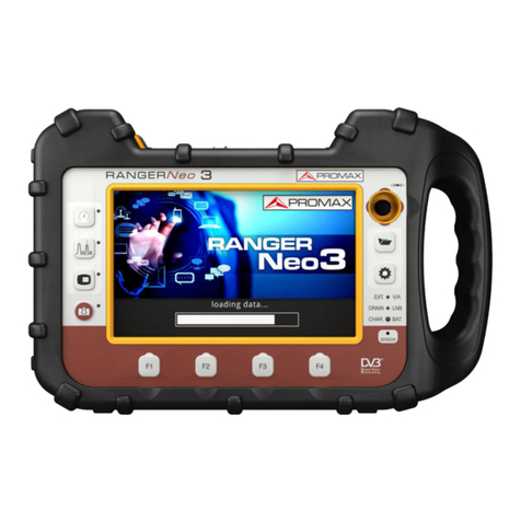
  9. Promax RANGER Neo 2 User manual

Promax RANGER Neo 2 User manual

Other manuals for RANGER Neo 2

3

This manual suits for next models

1

Other Promax Measuring Instrument manuals
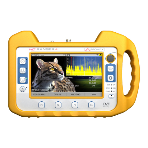
Promax HD Ranger + User manual

Promax

Promax HD Ranger + User manual

Promax OTDR Series User manual

Promax

Promax OTDR Series User manual
Promax 25 User manual

Promax

Promax 25 User manual

Promax HD Ranger + User manual

Promax

Promax HD Ranger + User manual

Promax RANGER mini User manual

Promax

Promax RANGER mini User manual

Promax PROLINK-4C User manual

Promax

Promax PROLINK-4C User manual

Promax RANGERNeo 4 User manual

Promax

Promax RANGERNeo 4 User manual

Promax PROFI-70 User manual

Promax

Promax PROFI-70 User manual

Promax 8 SE User manual

Promax

Promax 8 SE User manual

Promax Prolite-50 User manual

Promax

Promax Prolite-50 User manual

Promax MR-275 User manual

Promax

Promax MR-275 User manual

Promax PROLITE-53B User manual

Promax

Promax PROLITE-53B User manual

Promax PRODIG-3 User manual

Promax

Promax PRODIG-3 User manual

Promax PROLITE-57 User manual

Promax

Promax PROLITE-57 User manual

Promax CABLE RANGER User manual

Promax

Promax CABLE RANGER User manual

Promax PROPOWER - 5 User manual

Promax

Promax PROPOWER - 5 User manual

Promax MZ-505C User manual

Promax

Promax MZ-505C User manual

Promax HD RANGER 2 User manual

Promax

Promax HD RANGER 2 User manual

Promax PROMAX-10 User manual

Promax

Promax PROMAX-10 User manual

Promax 6 User manual

Promax

Promax 6 User manual

Promax RANGER mini User manual

Promax

Promax RANGER mini User manual

Promax TVHUNTER+ User manual

Promax

Promax TVHUNTER+ User manual

Promax MC-577 User manual

Promax

Promax MC-577 User manual

Promax 26 User manual

Promax

Promax 26 User manual
Popular Measuring Instrument manuals by other brands

Powerfix Profi 278296 Operation and safety notes

Powerfix Profi

Powerfix Profi 278296 Operation and safety notes

Test Equipment Depot GVT-427B user manual

Test Equipment Depot

Test Equipment Depot GVT-427B user manual

Fieldpiece ACH Operator's manual

Fieldpiece

Fieldpiece ACH Operator's manual

FLYSURFER VIRON3 user manual

FLYSURFER

FLYSURFER VIRON3 user manual

GMW TG uni 1 operating manual

GMW

GMW TG uni 1 operating manual

Downeaster Wind & Weather Medallion Series instruction manual

Downeaster

Downeaster Wind & Weather Medallion Series instruction manual

Hanna Instruments HI96725C instruction manual

Hanna Instruments

Hanna Instruments HI96725C instruction manual

Nokeval KMR260 quick guide

Nokeval

Nokeval KMR260 quick guide

HOKUYO AUTOMATIC UBG-05LN instruction manual

HOKUYO AUTOMATIC

HOKUYO AUTOMATIC UBG-05LN instruction manual

Fluke 96000 Series Operator's manual

Fluke

Fluke 96000 Series Operator's manual

Test Products International SP565 user manual

Test Products International

Test Products International SP565 user manual

General Sleep Zmachine Insight+ DT-200 Service manual

General Sleep

General Sleep Zmachine Insight+ DT-200 Service manual

Sensa Core Lacto Spark user manual

Sensa Core

Sensa Core Lacto Spark user manual

VOLTCRAFT UTS-1980 operating instructions

VOLTCRAFT

VOLTCRAFT UTS-1980 operating instructions

EBCHQ 94915 Operation manual

EBCHQ

EBCHQ 94915 Operation manual

Balluff BIP LD2-T017-01-EP-S4 Series user guide

Balluff

Balluff BIP LD2-T017-01-EP-S4 Series user guide

Pulsar IMP Lite Series instruction manual

Pulsar

Pulsar IMP Lite Series instruction manual

ETCR 6800 user manual

ETCR

ETCR 6800 user manual

manuals.online logo
manuals.online logoBrands
  • About & Mission
  • Contact us
  • Privacy Policy
  • Terms and Conditions

Copyright 2025 Manuals.Online. All Rights Reserved.

RANGER 2/3
Neo
QUICK REFERENCE GUIDE
OPTICAL OPTION + 5 GHz RF AUXILIARY INPUT
CONNECTION FOR FIBRE OPTICAL TEST
1
1FC-APC connector (optical signal input)
(2) Optical Module Enable and Wavelength* Selection
-5.0 dBm
-0.0 dBm
-2.0 dBm
Enable the optical module to
configure additional
parameters.
Disabled
External
Disabled
1490 nm
1310 nm
1550 nm
Fiber Optic Settings
Optical Module
Optical Module
CONFIGURATION OF SELECTIVE OPTICAL TO RF SIGNAL CONVERTER
Disabled
Enabled
1310 nm
1490 nm
1550 nm
Disabled
Enabled
1310 nm
Supply Output:
Supply Voltage:
Optical Module...
On
Module:
Wavelength:
Attenuator:
Module:
RF
Terrestrial
RF Demodulator
RF
Terrestrial
RF Demodulator
Fiber Optic
Terrestrial
RF Demodulator
(1) Optical Fibre Input Selection
Terrestrial Settings
RF
IP-TV
5GHz
Wi-Fi
Fiber Optic
Input
*Selection of wavelength to be converted to RF
Band:
Decoder TS Input:
Signal Source:
Band:
Decoder TS Input:
Signal Source:
Band:
Decoder TS Input:
Signal Source:
Test Equipment Depot - 800.517.8431 - 99 Washington Street Melrose, MA 02176
TestEquipmentDepot.com
RANGER 2/3
Neo
GUÍA DE REFERENCIA RÁPIDA
OPCIÓN ÓPTICA + ENTRADA RF AUX. 5 GHz
FIBRE OPTICAL TEST SELECTION
FIBRE OPTICAL TEST PERFORMANCE
( )Selective measurement of optical power on three bands: 1310/1490/1550 nm
Tools
LTE Ingress Test
Attenuation Test
Merogram
Fibre Optic Test
Exit Set Reference
04/03/2013 14:33
DEFAULT FIBRE OPTIC TEST
Advanced
CH
5h15
Wavelength:
Reference:
Current:
Attenuation:
1310 1490 1550 nm
dBm
dBm
dB
-9.7
-14.7
-5.0
-9.8
-9.8
0.0
-10.7
-12.7
-2.0
Fail Pass Pass
-30
-20
-10
0Max.
Th.
1
2
3
4
5
6
7
89
Status message depending on the level of attenuation.
Power level of the signal.
Wavelength of the signal (nm).
Power level of the reference signal, which is used to calibrate
and calculate the attenuation level (dBm).
Power level of the test signal at the user's access point (dBm).
Attenuation level (dB); Attenuation = Current - Reference.
"Advanced" key to access these options: Threshold attenuation
(see "Threshold" dashed line) and Max. attenuation (see "Maximal". dashed line).
"Exit" button to exit the screen.
"Set Reference" key to calibrate the reference signal.
1
2
3
4
5
6
7
8
9
CONFIGURATION FOR RF AUX. INPUT SIGNAL MEASUREMENT
* 4Band 1: 2000 - 3000 ; Band 2: 3 00 - 4400 MHz; Band 3: 4400 - 6000 MHz MHz
CONNECTION FOR RF AUXILIARY INPUT SIGNAL MEASUREMENT
Terrestrial Settings
Band:
Decoder TS Input:
Signal Source: RF
Terrestrial
RF Demodulators
Band:
Decoder TS Input:
Signal Source: RF
Terrestrial
RF Demodulator
Terrestrial Settings
RF
IPTV
Fiber Optic
Wi-Fi
RF AUX
Band:
Decoder TS Input:
Signal Source: RF AUX
Terrestrial
RF Demodulator
Terrestrial Settinss
1
Signal Source:
Attenuator:
Band:
RF AUX
Disabled
Band 1
External RF AUX Input
Signal Source:
Attenuator:
Band:
RF AUX
Disabled
Band 1
External RF AUX Input
Band 1
Band 2
Band 3
Signal Source:
Attenuator:
Band:
RF AUX
Disabled
Band 3
External RF AUX Input
1SMA Connector (RF aux. input signal)
(1) Aux. Input Signal Selection (2) Band Selection*
RANGER 2/3
Neo
QUICK REFERENCE GUIDE
OPTICAL OPTION + 5 GHz RF AUXILIARY INPUT
USER MANUAL
DOWNLOAD
v1.0
RF AUX. INPUT SIGNAL MEASUREMENT EXAMPLES
Example of RF Aux. Input Signal at Band 3
1
2
3
RF Aux. Input Signal Power
Auxiliary Frequency Input
Input Signal Frequency
LNB Optical Power Level
RF Auxiliary Input Enabled
Center Frequency
4
5
6
Example of RF Aux. Input Signal at Band 1
OPT
4
5
6
1
2
3
22/03/2017 ( )0 DG0302
PDF
RANGER 2/3
Neo
QUICK REFERENCE GUIDE
OPTICAL OPTION + 5 GHz RF AUXILIARY INPUT
RANGER 2/3
Neo
99 Washington Street
Melrose, MA 02176
Phone 781-665-1400
Toll Free 1-800-517-8431
Visit us at www.TestEquipmentDepot.com