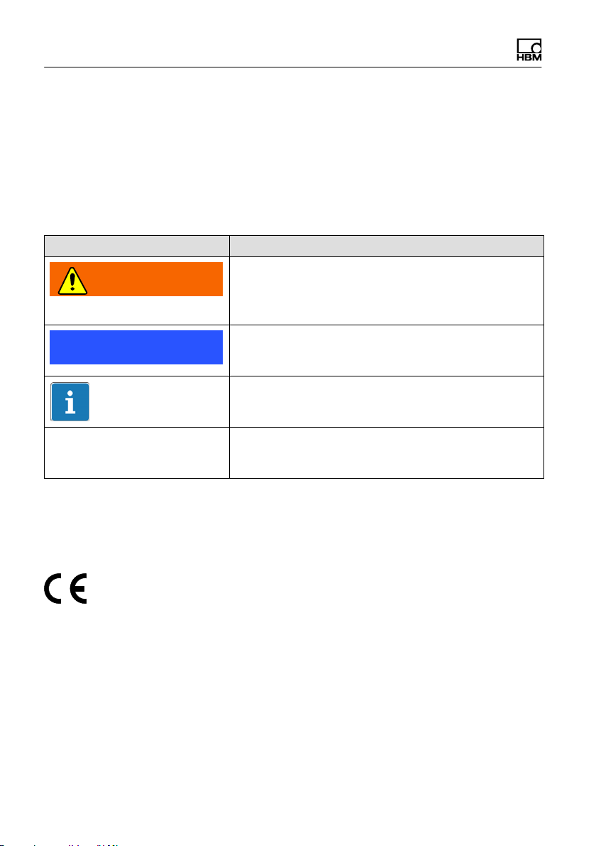
HBM Z16A User manual

Operating Manual | Bedienungsanleitung |
Manuel d'emploi
English Deutsch Français
Z16A

Hottinger Baldwin Messtechnik GmbH
Im Tiefen See 45
D-64293 Darmstadt
Tel. +49 6151 803-0
Fax +49 6151 803-9100
www.hbm.com
Mat.: 7-0101.0020
DVS: A04000_03_Y00_00 HBM: public
01.2020
EHottinger Baldwin Messtechnik GmbH.
Subject to modifications.
All product descriptions are for general information only.
They are not to be understood as a guarantee of quality or
durability.
Änderungen vorbehalten.
Alle Angaben beschreiben unsere Produkte in allgemeiner
Form. Sie stellen keine Beschaffenheits- oder Haltbarkeits
garantie dar.
Sous réserve de modifications.
Les caractéristiques indiquées ne décrivent nos produits
que sous une forme générale. Elles n'impliquent aucune
garantie de qualité ou de durabilité.

Operating Manual | Bedienungsanleitung |
Manuel d'emploi
English Deutsch Français
Z16A

2A04000_03_Y00_00 HBM: public Z16A
English
1 Safety instructions 3........................................
2 Markings used 6............................................
2.1 The marking used in this document 6...........................
2.2 Symbols on the device 6......................................
3 Scope of delivery 7.........................................
4 Structure and mode of operation 8...........................
5 Conditions on site 9........................................
6 Mechanical installation 11....................................
6.1 Important precautions during installation 11......................
6.2 Mounting and load application 12...............................
7 Electrical connection 13......................................
7.1 Connection in six-wire configuration 13..........................
7.2 Connection in four-wire configuration 13.........................
7.3 Shortening the cable 14.......................................
7.4 Cable extension 14...........................................
7.5 Parallel connection 15.........................................
7.6 EMC protection 15............................................
8 Waste disposal and environmental protection 17..............
9 Specifications 18............................................
10 Dimensions 20..............................................
10.1 Z16A… 20...................................................
10.2 Z16A… (7.5 t + 15 t) with knuckle eyes 21.......................
10.3 Z16A... with threaded connector 22.............................

Safety instructions
Z16A A04000_03_Y00_00 HBM: public 3
1 Safety instructions
Appropriate use
Transducers of the Z16A... type series are designed for technical weighing
applications within the limits detailed in the specifications. The load cell must
only be used for tensile loads. Any other use is not appropriate.
Any person instructed to carry out installation, commissioning or operation of
the transducer must have read and understood the Operating Manual and in
particular the technical safety instructions.
In the interests of safety, the transducer should only be operated by qualified
personnel and as described in the Operating Manual. It is also essential to
comply with the legal and safety requirements for the application concerned
during use. The same applies to the use of accessories.
The transducer is not intended for use as a safety component. Please also
refer to the section: "Additional safety precautions". Proper and safe operation
requires proper transportation, correct storage, siting and mounting, and
careful operation.
Operating conditions
SPlease observe the permissible maximum values stated in the
specifications for:
- Limit load
- Breaking loads
- Temperature limits
- Limits of electrical loading capacity
SNote, that when several transducers are installed in a scale, there is not
always an even distribution of load on the individual transducers.
SThe transducers can be used as machine elements. When used in this
manner, it must be noted that, to favor greater sensitivity, the transducer
has not been designed with the safety factors usual in mechanical
engineering.

Safety instructions
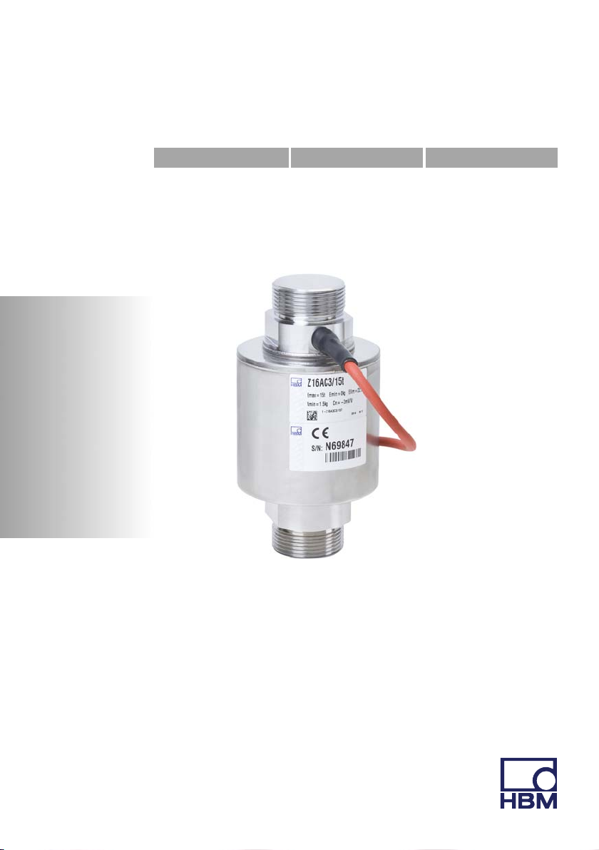
4A04000_03_Y00_00 HBM: public Z16A
SThe transducer must not be modified from the design or safety engineering
point of view except with our express agreement.
SThe transducer is maintenance-free.
SIn accordance with national and local environmental protection and material
recovery and recycling regulations, old transducers that can no longer be
used must be disposed of separately and not with normal household
garbage, see Chapter 8, Page 17.
Explosion protection version option
SPlease comply with the relevant code of practice during installation.
SThere must be compliance with the installation conditions cited in the
Certificate of Conformity and/or the Type Certificate.
Qualified personnel
Qualified persons means persons entrusted with the installation, fitting,
commissioning and operation of the product who possess the appropriate
qualifications for their function.
This includes people who meet at least one of the three following requirements:
SKnowledge of the safety concepts of measurement and automation
technology is a requirement and as project personnel, they must be familiar
with these concepts.
SAs measurement or automation plant operating personnel, they have been
instructed how to handle the machinery. They are familiar with the operation
of the equipment and technologies described in this documentation.
SAs commissioning engineers or service engineers, they have successfully
completed the training to qualify them to repair the automation systems.
They are also authorized to activate, ground and label circuits and
equipment in accordance with safety engineering standards.
Additional safety precautions
Additional safety precautions to meet the requirements of the relevant national
and local accident prevention regulations must be taken in plants where
malfunctions could cause major damage, loss of data or even personal injury.

Safety instructions
Z16A A04000_03_Y00_00 HBM: public 5
The scope of supply and performance of the transducer covers only a small
area of measurement technology. Before starting up the transducer in a
system, a project planning and risk analysis must first be implemented, taking
into account all the safety aspects of measurement and automation technology
so that residual risks are minimized. This particularly concerns personal and
machine protection. The transducers function passively and cannot implement
any (safety-relevant) cutoffs. In the event of a fault, the relevant precautions
must establish safe operating conditions.
General dangers of failing to follow the safety instructions
The transducer corresponds to the state of the art and is failsafe. The
transducer may give rise to residual dangers if it is inappropriately installed or
operated.

Markings used
6A04000_03_Y00_00 HBM: public Z16A
2 Markings used
2.1 The marking used in this document
Important instructions for your safety are specifically identified. It is essential to
follow these instructions in order to prevent accidents and damage to property.
Symbol Significance
WARNING This marking warns of a potentially dangerous
situation in which failure to comply with safety
requirements can result in death or serious physical
injury.
Note This marking draws your attention to a situation in
which failure to comply with safety requirements can
lead to damage to property.
Important
This marking draws your attention to important
information about the product or about handling the
product.
Emphasis
See …
Italics are used to emphasize and highlight text and
identify references to sections, diagrams, or external
documents and files.
2.2 Symbols on the device
CE certification
The CE mark enables the manufacturer to guarantee that
the product complies with the requirements of the
relevant EC directives (the Declaration of Conformity can
be found on the HBM website (www.hbm.com) under
HBMdoc).

Scope of delivery
Z16A A04000_03_Y00_00 HBM: public 7
3 Scope of delivery
Included in the scope of supply:
SSG with connecting cable
SBag with lubricating grease
SAssembly instructions
Accessories (not included in the scope of supply)
SKnuckle eye, Order No. 1-U2A/10T/ZGOW
SThread adapter M36x3, Order No. 1-Z16/ADAPTERM36X3
SGround cable, Order No. e.g. 1-EEK6

Structure and mode of operation
8A04000_03_Y00_00 HBM: public Z16A
4 Structure and mode of operation
The measuring element is a steel loaded member to which strain gages (SG)
are applied. The SG are arranged so that two are stretched and the other two
compressed when a load acts on the transducer.

Conditions on site
Z16A A04000_03_Y00_00 HBM: public 9
5 Conditions on site
Series Z16A... load cells are hermetically encapsulated and are therefore not
at all sensitive to the influence of moisture and humidity. The transducers
achieve protection class IP68 (test conditions: 100 hours under 1m water
column) and and IP69K (water at high pressure, steam cleaner), as per DIN
EN60529. Nevertheless, the load cells must be protected against constant
humidity and moisture.
Protection against corrosion
The load cell must be protected against chemicals that could attack the
transducer body steel.
Notice
Acids and all substances that release ions also attack stainless steels and their
welded seams.
Should there be any corrosion, this could cause the transducer to fail. If this is
the case, you must provide appropriate means of protection.
Cable protection
In applications where the TPE cable of the load cell can be chemically or
mechanically attacked or destroyed, protect the cable additionally by means of
standard cable protection systems. The load cell is fitted with an adapter that
has an outer diameter of 10mm to attach flexible cable protection tubing.
Mount the protection tubing with a cable tie or a hose clamp on the adapter.
Explosion protection version option
The ambient temperature range specified on the transducer must not be
exceeded.

Conditions on site
10 A04000_03_Y00_00 HBM: public Z16A
Deposits
Dust, dirt and other foreign matter must not be allowed to accumulate
sufficiently to divert some of the measuring force onto the housing, thus
invalidating the measured value (force shunt).

Mechanical installation
Z16A A04000_03_Y00_00 HBM: public 11
6 Mechanical installation
6.1 Important precautions during installation
SHandle the transducer with care.
SWelding currents must not be allowed to flow over the transducer. If there is
a risk that this might happen, you must provide a suitable low-ohm
connection to electrically bypass the transducer. HBM, for example,
provides the highly flexible EEK ground cable, which can be screwed on
above and below the transducer.
SMake sure that the transducer cannot be overloaded.
SThe optional cable with an outer braided wire covering for the configurable
K-Z16A3 with option 20R, is intended for use when there is increased
mechanical stress (e.g. damage caused by gnawing rodents). If this cable is
used, the outer braided wire has to be connected to potential equalization at
least once, to avoid accidental energization. This outer braided wire is not
used to shield the load cell. The inner braid of the load cell cable is used for
shielding (also refer to 7.6 EMC protection).
WARNING
There is a danger of the transducer breaking if it is overloaded. This can cause
danger for the operating personnel of the system in which the transducer is
installed.
Implement appropriate safety measures to avoid overloads or to protect
against the resulting dangers.
Notice
Load cells are precision measuring elements and need to be handled carefully.
Dropping or knocking the transducer may cause permanent damage. Make
sure that the transducer cannot be overloaded, including while it is being
mounted.

Mechanical installation
12 A04000_03_Y00_00 HBM: public Z16A
6.2 Mounting and load application
The Z16A... type series load cells can measure axial loads in the tensile
direction. Load is applied via two threaded bolts. The bearing surfaces of the
mounting parts to be screwed on must be clean and flat.
The following table contains the tightening torques to be used, the tightening
torque must not be applied via the load cell:
Nominal (rated) load Load cell thread Tightening torque
7.5t M39x2 600 N⋅m
15t M39x2 1200N⋅m
20 t M39x2 2000 N⋅m
Notice
Apply sufficient lubricating grease to the threaded bolts on the load cell
(included with the load cell). This not only achieves optimal mounting, it also
protects against wear and corrosion.
The load must act as accurately as possible in the direction of measurement.
Torsional moments, eccentric loads and lateral or side forces cause
measurement errors and can permanently damage the load cell. Catch such
interference effects, e.g. using lateral stay bars or guide rollers, but ensure that
these elements do not absorb any load or force components in the direction of
measurement (force shunt which will in turn lead to measurement errors).
WARNING
Comply with the maximum permissible loading capacities of the mounting parts
used. If the loading capacity does not match the nominal (rated) range of the
load cell, there is a danger of the component failing. This not only can cause
damage to property, serious injuries can occur with regards to the nominal
(rated) loads of the load cells in type series Z16A... up to 20 t.
To minimize errors during load application, HBM recommends using knuckle
eyes. They are suitable for use with quasi-static loading (load cycles <10 Hz).

Electrical connection
Z16A A04000_03_Y00_00 HBM: public 13
7 Electrical connection
The following can be connected for measurement signal conditioning:
SCarrier-frequency amplifiers
SDC amplifiers
designed for strain gage measurement systems.
The load cells are delivered with a six-wire configuration. Optionally available
with different cable lengths.
7.1 Connection in six-wire configuration
white
black
gray
Excitation voltage (+)
green
red
Shield / drain wire connected to
transducer housing
Excitation voltage (-)
Sense lead (-)
Measurement signal (+)
blue
Sense lead (+)
Measurement signal (-)
Fig. 7.1 Pin Assignment
With this connector pin assignment, the output voltage at the measuring
amplifier is positive in the tensile direction when the transducer is loaded.
7.2 Connection in four-wire configuration
When transducers in a six-wire configuration are connected to amplifiers in a
four-wire configuration, the sense leads of the transducer must be connected
to the corresponding excitation voltage leads: Marking (+) with (+) and marking
(-) with (-), see Fig. 7.1. This measure also reduces the cable resistance of the

Electrical connection
14 A04000_03_Y00_00 HBM: public Z16A
excitation voltage leads. However, there will be a voltage loss on the supply
leads due to the cable resistance that is still present and not compensated for
by the six-wire configuration. A large part of this loss can be eliminated by a
calibration, however, the temperature-dependent part remains.
Important
The TKcvalue given in the specifications for the transducer therefore does not
apply for the cable and transducer combination when connection is in a four-
wire configuration, where the cable percentage must be added.
7.3 Shortening the cable
If the transducer is connected to an amplifier in a six-wire configuration, the
transducer cable can be shortened as required, without adversely affecting the
measurement accuracy.
7.4 Cable extension
Only use shielded, low-capacitance measurement cables for extending. Ensure
that connection is perfect, with a low contact resistance.
The cable of a six-wire transducer can be extended with a cable of the same
type.
Cable types recommended by HBM:
SKAB8/00‐2/2/2 (by the meter, Order No. 4‐3301.0071 for gray or
4‐3301.0082 for blue version)
SCABA1 (cable roll, Order No. CABA1/20 = 20 m or CABA1/100 = 100m
long)

Electrical connection
Z16A A04000_03_Y00_00 HBM: public 15
7.5 Parallel connection
Important
When connecting load cells in parallel, the cables between the load cells and
the terminal box in which they are to be interconnected must be identical and
of the same length: Different cable lengths or types between the terminal box
and load cells can not be compensated by the six-wire configuration. Either fit
all load cells with the same cable type and length, or shorten all cables to the
same length. Otherwise you will have to calculate correction resistances in
order achieve identical circumstances for the individual load cells.
Only load cells with an aligned output (nominal (rated) sensitivity and output
resistance) are suitable for parallel connection. This is the case for the type
Z16A... load cells. The load cells can be wired in parallel by joining the load cell
cable core ends of the same color. The type VKK terminal boxes or the
VKK2R-8 Ex version for potentially explosive areas are available in the HBM
product line for this purpose. The output signal is then the average of the
individual output signals.
Important
Overloading in an individual load cell cannot then be detected from the output
signal after load cells have been connected in parallel.
7.6 EMC protection
Important
The load cells with shielded, round cables are EMC-tested in accordance with
EC directives and identified by CE certification. However, you must connect the
shield of the connection cable extensively on the shielding electronics
enclosure in order to achieve EMC protection for the measuring chain.

Electrical connection
16 A04000_03_Y00_00 HBM: public Z16A
Electrical and magnetic fields often induce interference voltages in the
measuring circuit. Therefore:
SUse shielded, low-capacitance measurement cables only (HBM cables fulfill
both conditions).
SConnect the shielding extensively, not punctiform (connect over large
surface area).
SDo not route the measurement cables parallel to power lines and control
circuits. If this is not possible, protect the measurement cable with e.g.
steel conduit.
SAvoid stray fields from transformers, motors and contact switches.
SDo not ground the transducer, amplifier and indicator more than once.
SConnect all the devices in the measuring chain to the same protective earth
conductor.

Waste disposal and environmental protection
Z16A A04000_03_Y00_00 HBM: public 17
8 Waste disposal and environmental protection
The correct disposal of old equipment prevents ecological damage and health
hazards.
As waste disposal regulations may differ from country to country, we ask that
you contact your supplier to determine what type of disposal or recycling is
legally applicable in your country.
Packaging
The original HBM packaging is made from recyclable material and can be sent
for recycling. Store the packaging for at least the duration of the warranty.
For ecological reasons, empty packaging should not be returned to us.

Specifications
18 A04000_03_Y00_00 HBM: public Z16A
9 Specifications
Type Z16AD1 Z16AC3
Accuracy class1) D1 C3
Number of load cell verification
intervals
nLC 1000 3000
Nominal (rated) load Emax t 7.5 15 20 15
Minimum load cell verification
interval
vmin Emax/5000 Emax/10,000
Temperature coefficient of zero
signal per 10K
TC0% of
Cn
±0.0285 ±0.0140
Nominal (rated) sensitivity2) CnmV/V 2
Sensitivity tolerance % ±0.5
Temperature coefficient of
sensitivity per 10K3) TCS
% of
Cn
±0.0250 ±0.0080
Linearity error3) dlin ±0.0300 ±0.0180
Relative reversibility error3) dhy ±0.0330 ±0.0170
Load creep in 30 min. dcr ±0.0330 ±0.0167
Input resistance RLC
Ω
700 ±20
Output resistance2) R0706 ±3.5
(for 40 m cable length 711 ±3.5)
Reference excitation voltage Uref
V
5
Nominal (rated) range of the
excitation voltage
BU0.5 ... 12
Insulation resistance at 100VDC Ris GΩ> 5
Nominal (rated) ambient
temperature range
BT
°C
-10 ... +40
Operating temperature range Btu -30 ... +70
Storage temperature range Btl -50 ... +85
This manual suits for next models
2
Table of contents
Languages:
Other HBM Transducer manuals
Popular Transducer manuals by other brands

Balluff
Balluff MICROPULSE BTL7-A/E1 0-M Series manual

Multitek
Multitek PowerSig M560-AT operating manual

Clark Synthesis
Clark Synthesis TST429 specification

Furuno
Furuno SS542 Owner's guide & installation instructions

TWK Elektronik
TWK Elektronik PMU-04 user manual

Sensor Technology
Sensor Technology TorqSense RWT410 Series user manual

Fairchild
Fairchild T79 Series Maintenance and operating instructions

Dwyer Instruments
Dwyer Instruments 2200 Series Installation and operating instructions

promesstec
promesstec UMU 500 user manual

Panametrics
Panametrics T5 installation guide

HSE
HSE PLUGSYS TAM-A operating instructions

Balluff
Balluff BTL7-A50 Series user guide