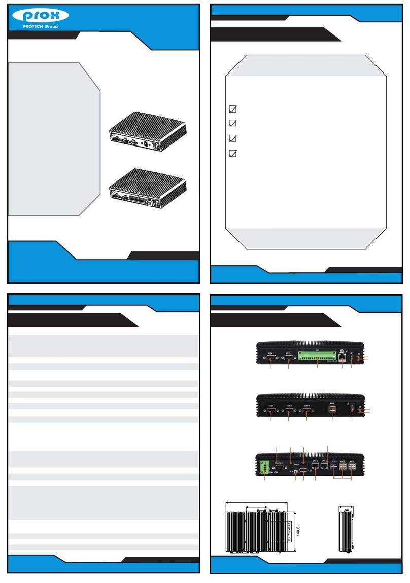
Ver. Q3
All Rights Reserved. Copyright 2022
Quick
Reference
Guide
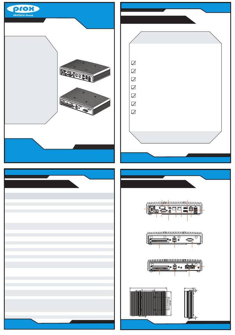
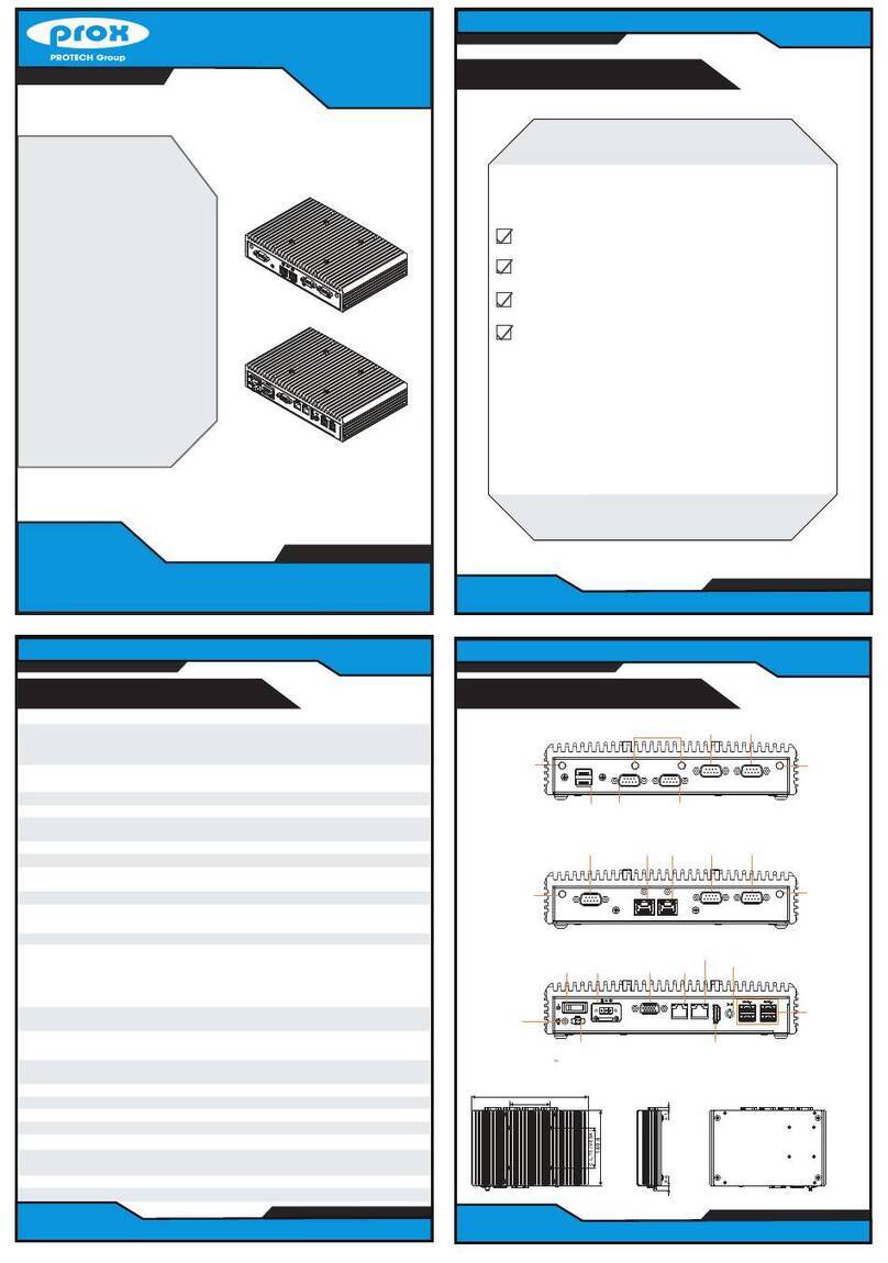
Remote
Switch
DC IN
DIO
DVI-I COM3
COM4
COM1
COM2
POE ON
1
2
1
2
I2C
LAN USB 3.0
DC IN 9~36V
Remote
Switch
DVI-I
DIO
COM3
COM4
COM1
COM2
POE ON 1
2
2
1
LAN USB 3.0
I2C
Specifications
SE-8400
System
CPU Support 6th Gen. Intel®Core™ i7/i5/i3 & Pentium/Celeron®LGA1151
socket processor (CPU TDP max. up to 35W)
Chipset Intel®Q170/ H110
Memory Support 2 x DDR4 2133MHz SO-DIMM up to 32 GB
Drive Bay 2 x 2.5” SATAIII HDD/SSD (support RAID 0/1 in Q170 SKU only)
Audio 1 x Line In / 1x Line Out / 1 x Mic
Expansion Slots 1 x Full-sized mini-PCIe (mini PCIe, USB and SIMsignals)
1 x Half-sized mini-PCIe (mini PCIe and USB signals)
1 x SIMcard slot /1x CFast slot
Weight / Dimensions 4.5 kg/ 260mm(W) x 80mm(H) x 200mm(D)
Power Input DC In 9~36V
Certificate FCC/CE
I/O Ports (Front side)
Display 1 x HDMI
USB 2 x USB 3.0 (Q170), 2 x USB 2.0 (H110)
Serial Ports COM 5/6 for RS-232 (optional)
Parallel Port 1 x LPT port (optional)
Intel LAN Chip (optional)
SIM card / CFast slot 1 x SIMcard slot / 1x CFast slot
Power Output 1 x 3-pin terminal block for DC-out 5V/12V (1A max)
I/O Ports (Rear side)
Display 1 x DVI-I (DVI-D+VGA)
USB 4 x USB 3.0
Serial Port COM3/4 for RS-232
COM1/2 for RS-232/422/485 (selectable under BIOS)
[COM1/2 for +5V/+12V/RI selectable by jumper]
LAN 2 x GbE LAN, Wake-On-LAN, PXE
LAN 1: Intel®PHY 219 LM (10/100/1000 Mbps)
LAN 2: Intel®LAN 210 AT (10/100/1000 Mbps)
Digital I/O Port 8 in / 8 out, DSUB-25 type or 16-pin terminal block (optional)
Audio 1 x Line-in / 1x Line-out / 1 x MIC
Power Input DC in 9~36V (DIN type 4-pin connector or 3-pin terminal block)
Power On/Off 1 x power button, 1 x remote switch
Environment
Operating Temp. HDD: 0°C ~ 40°C (32°F ~ 104°F)
(with airflow) SSD: 0°C ~ 50°C (32°F ~ 112°F)
Storage Temp. -20°C ~ 80°C (-4°F ~ 176°F)
Humidity 20% ~ 90%
Note: More Jumper Settings are shown on the next page.
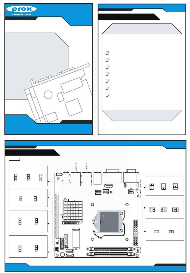
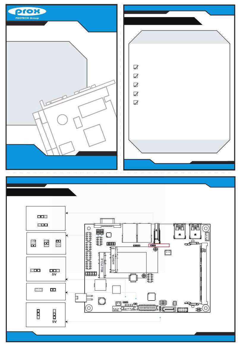
Flash Descriptor Override Selection
Disable
(default)
11
Enable
BIOS Recovery Mode Selection
Normal
(default)
Recovery
11
CFast Voltage Control Selection
3.3V 5V
(default)
1
1
DVI1
COM3
COM4
COM1
COM2
JP4
56
1
2
1
5
2
6JP15
JP12
12
JP7 13
DIO1
115
216
1
3
2
4ATX_PWR1
1 3
JP17
LED1
PWR_IN1
LAN1USB1
AUDIO1
12
3
4
I2C1
1
2
JP16
M_PCIE1
PWR_BTN1
PWR_BTN2
SATA2
SATA_PWR2
SATA1
SATA_PWR1
COM6
COM5
USB2
RST_SW1 HDMI1
PWR_OUT1
1 3
JP9
CFAST1
LVDS1
12
2930
JLPC1
LPT1
HDDLED1
PWRLED1
PCI_E1
INV1
SO-DIMM1
5
6
1
21
2
5
6
1
2
6
5
JP3 JP1 JP2
M_PCIE2
CMOS1
1
1
2
2
1
2
15
16
17
18 52
51
1
2
15
16
17
18
51
52
13
12
1920
114
13
26
1
1
2
2
1
6
LAN2
12
COM1 Pin9 and COM2 PIN18
Definition Selection Guide
JP15JP12
RI
12V
5V
5
1
6
2
2
5
1
6
2
2
5
1
6
2
5
1
6
2
5
1
6
2
2
5
1
6
2
2
(default)
VCCIO Voltage Selection
0.95V 1.0V
(default)
11
Hardware Power
Failure Selection
Disable
(default)
Enable
1
1
Clear CMOS Data Selection
Nromal Clear CMOS
(default)
11
Jumper Setting
SE-8400
SE-8400
LAN3 & LAN4
