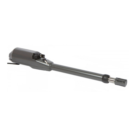
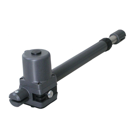
Proteco MyGate myaster Guide

myaster
2011_13
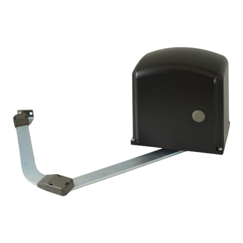
AUTOMATISMES POUR PORTAILS A BATTANTS
AUTOMATION FOR SWING GATES
AUTOMATISIERUNG FÜR FLÜGELTORE
AUTOMATIZACIONES PARA VERJAS CON HOJAS
Manuel d'Installation et Utilisation.
Installation and use manual
Handbuch der Installation und des Gebrauchs
Manual de Uso e Instalación
PRODUITS
PRODUCTS
ERZEUGNIS
PRODUCTOS ESAB, ul. Radomska 57, 26-900 Kozienice
tel.: 0-48 614 32 24, www.esab.net.pl
Instrukcja Montażu i Obsługi
PRODUKTY
AUTOMATYKA DO BRAM SKRZYDŁOWYCH

CARATTERISTICHE TECNICHE - CARACTERISTIQUES TECHNIQUES - TECHNICAL FEATURES - TECHNISCHE DATEN - CARACTERÍSTICAS TÉCNICAS
myaster 3 myaster 4 myaster 5
myaster 3 24
myaster 4 24 myaster 3 110
myaster 5 24 myaster 4 110
Alimentazione - Alimentation - Power supply - Anschluss - Alimentaci n
Assorbimento - Consommation - Absorption - Stromaufnahme - Absorción de línea
Potenza - Puissance moteur - Motor power - Motorleistung - Potencia
Condensatore - Condensateur - Capacitor - Kondensator - Condensador
Protezione termica - Protection thermique - Thermic protection
Thermoschutz - Protecci n térmica
Spinta max - Poussée - Maximum thrust - Drehmoment - Empuje máx
Grado IP - Classe IP - IP level - Schutzart IP - Grado de protección IP
Giri motore - Vitesse moteur - Motordrehzahl - Rotación del motor
Temperatura di funzionamento - Température de service - Working temperature
Temperaturbereich - Temperatura de servicio
Lunghezza max anta - Vantail maximum - Leaf’s maximum length
Max. Flügelgellänge - Longitud máx. hoja
Peso max anta - Poids maximum du vantail - Leaf-s maximum weight
Max. Flügelgewicht - Peso máx. hoja
Corsa max - Course standard - Standard stroke - Laufweg - Carrera máx.
Angolo max di apertura - Angle max d’ouverture - Maximum opening
Max. Öffnungswinkel - Ángulo máx. de abertura
Tempo di apertura 90° - Temps d’ouverture 90°- 90° opening time
Öffnungszeit - Velocidad angular 90°
Ciclo di lavoro - Cycle de travail - Duty cycle - Benutzungshäufigkeit - Ciclo de trabajo
ó
ó
Revolutions speed -
230V ~ 50Hz
1,2 - 1,7 A
280 W
10 µF
2800 N
54
1400 g/m
110° 110° 110°
40 % 80 % 40 %
150° 150°
24V dc
0,5 - 7,5 A
50 W
110V dc
2,5 - 2,6A
300 W
30 µF
2500 N
54
1600 g/m
3000 N
54
1600 g/m
17” 15”
2,00 m 2,00 m
350 Kg 275 Kg 350 Kg
300 mm 300 mm 300 mm
22” 20” 25” 18”15”
27”
2,75 m 2,50 m 2,00 m
300 Kg 250 Kg 200 Kg 300 Kg
400 mm 400 mm 400 mm
3,50 m 3,00 m 2,75 m
250 Kg
500 mm 500 mm
_____
_____
-20° - +55°C -20° - +55°C -20° - +55°C
1
2
3
4
1
2
3
4
5
5
n° 1 Attuatore / Actionneur / Actuator / Triebwerk / Actuador
n° 1 S1 Staffa / Patte / Bracket / Bügel / Abrazadera
n° 1 PR1 - G1 Kit fissaggio / Kit de fixation / Fixing kit
Kit Befestigung / Kit de fijación
n° 1 S3 Staffa / Patte / Bracket / Bügel / Abrazadera
n° 1 Chiave di sblocco / Clé de deblocage / Release key
Freisetzung des Schlüssel / Llave de desbloqueo
n° 1 Manuale d’Installazione e Uso
Manuel d'Installation et Utilisation
Installation and Use Manual
Handbuch der Installation und des Gebrauchs
Manual de Uso e Instalación.
N° 1 Manuale Generalità / Manuel Generalites
General Instructions manual / Handbuch Allgemeines
Manual Generalidades
A
230V
A
C
C¹
D
F + G
E
D
Descrizione
Description - Description
Beschreibung - Descripción 230Volt
Attuatore - Operateurs
Actuators - Triebwerk
Pistón
Quadro - Electronique -
Control Unit- Elektroschrank
Elektroschrank
Fotocellula - Photocellule Rx
Photocells Tx
Fotozelle - Fotocélulas
Antenna - Antenne - Aerial
Antenne - Antena
A
B
C
C1
E
1
2
3
4
3x1,5+T
2x1,5+T
4x0,75
2x0,75
2x0,75
12Volt
2x1
2x1,5+T
4x0,75
2x0,75
2x0,75
Ricevitore radio - Recepteur radio
Radio receiver - Funkempfganger
Receptor radio
Lampeggiante - Clignotant
Warning light
Blinkleuchte - Intermitente
Selettore a chiave
Selecteur a clé - Key contactor
Selector de llave - Schlusselchalter
G
F
D
5
6
7
2x0,75
2x0,75
2x0,75
2x0,75
2x0,75
2x0,75
myaster 3: Closed = 665 / Open = 980
myaster 4: Closed = 765 / Open = 1180
myaster 5: Closed = 865 / Open = 1380
myaster 3: 410
myaster 4: 510
myaster 5: 610
2020
169
70
99
88 55 63
COMPOSIZIONE - COMPOSITION - COMPOSITION
KOMPOSITION - COMPOSICIÓN
SCHEMA FUNZIONALE - SCHÉMA DE PRINCIPE - OPERATIONAL DIAGRAM
FUNKTIONSPLAIN - ESQUEMA FUNCIONAL
CHARAKTERYSTYKA TECHNICZNA
Zasilanie
Zużycie mocy
Moc silnika - Puissance moteur
Kondensator
Ochrona termiczna
Siła maks.
Kat. ochrony IP - Classe IP
Obroty silnika
Temperatura pracy
Maks. długość skrzydła
Skok standardowy - Course standard
Maks. kąt otwarcia
Maks. ciężar skrzydła
Czas otwarcia do 90°
Cykl pracy
SCHEMAT DZIAŁANIA
KOMPONENTY
Zamknięty
Zamknięty
Zamknięty
Otwarty
Otwarty
Otwarty
Opis
Siłowniki
Elektroniczna jednostka sterująca - Electronique
Fotokomórki
Antena
Radioodbiornik
Lampa ostrzegawcza - Clignotant
Stycznik kluczykowy
Siłownik
S1 Wspornik
PR1 - G1 Zestaw montażowy
S3 Wspornik
Klucz zwalniający
Instrukcja montażu i obsługi
Instrukcje ogólne

200 mm
/
/
175 mm
/
/
150 mm
A= 9 8
B=202
52
125 mm
A=123
B=177
52
100 mm
52
75mm
82
50mm
3
A=168
B=132
82
S1
S1 S1 S2S1S1
S2S2S1S1
S1 S1
S1
S1
A=143
B=157
A=148
B=152
A= 1 4 8
B=252
52
A= 1 7 3
B=227
52
A= 1 9 8
B=202
52
A=193
B=207
82
A= 2 1 8
B= 1 8 2
82
A=213
B=187
112
A=205
B=195
145
A=248
B=252
52
A=243
B=257
82
A=268
B=232
82
A=263
B=237
112 S2
A=255
B=245
145
A= 2 8 0
B= 2 2 0
145
A=305
B=195
145
4
5
DD
S1 S1S1 S1
TABELLA 1 myaster 3 A=145 B=145 myaster 4 A=195 B=195 myaster 5 A=245 B=245
Fig. I
PR1
Foro filetto
verso il basso
G1
Fig. M
myaster 3 345 mm
myaster 4 445 mm
myaster 5 545 mm
55 mm
Fig. A
A
DB
Fig. B
A
B
Fig. C
Centrale
elartneC
2
1
S1 dx
S1 sx
Fig. E
Fig. D
B B
B
B = Fermi meccanici
S2
S2 dx
sx
Fig. F
1
2
Fig. G
Fig. H
Min. 30 mm
Fig. P
A
DB
Fig. N
Fig. L
Fig. O
S3
2 cm
PR1
G1
ograniczniki mechaniczne
Centralny
Centralny
Otwór pod gwint
od dołu
TABELA 1

POLSKI
KRYTERIA BEZPIECZEŃSTWA
1 Uwaga:przedrozpoczęciempracyprzyurządzeniunależyzapoznaćsięzcałą
Instrukcją.
2 Wykonać testy sprawdzające, czy parametry siłownika odpowiadają potrze-
bomnabywcy.
3 Sprawdzić,czy:
-Zawiasybramysąwdobrymstanieiprawidłowozamocowane.
-Bramaposiadamechaniczneogranicznikiruchuwpozycjiotwarciaizatrzy-
mania.
ZALECENIA DOTYCZĄCE INSTALACJI
Połączenia:
• Patrz„Schematdziałania”izapoznajsięzeschematemcentralisterowniczej.
• Przewódelektrycznywychodzącyzsiłownikaniepowinienbyćnaprężony,ale
szerokozagiętykudołowiabyuniknąćszarpnięciasiłownika.(Rys.O)
• Regulacjęnależywykonywaćprzywyłączonymzasilaniuurządzenia.
• Należy przewidzieć wyłącznik wielobiegunowy blisko urządzenia (minimalny
wymiar styku: 3mm). Zawsze zabezpieczać zasilacz wyłącznikiem automa-
tycznym6Alubjednofazowymwyłącznikiem16Azbezpiecznikami.
• Przewodyzasilająceprowadzącedosilnikówijednostkisterującejorazprze-
wodyłączącezelementamiwyposażeniadodatkowegopowinnybyćoddzielo-
ne,abyuniknąćewentualnychzakłóceńwpracyinstalacji.
• Przypodłączaniudojednostkisterującejwszystkieurządzeniadodatkowe(za-
równosterujące,jakizabezpieczające)powinnybyćodłączoneodzasilania.
Części zamienne:
• Stosowaćwyłącznieoryginalneczęścizamienne.
• Akumulatoryusuwaćwrazzodpadamiprzemysłowymi(Ust.nr475/88).
Instalacja:
• W celu zapewnienia prawidłowej eksploatacji urządzenia i wyeliminowania
możliwościpowstaniaobrażeńlubuszkodzeńnależyzapoznaćsięztreścią
strony„Instrukcjeogólne”stanowiącejintegralnączęśćniniejszejInstrukcji.
• Użytkowaniesprzętupowinnobyćzgodnezprzepisamibezpieczeństwaobowią-
zującymiwkrajuużytkownikaoraznormamidotyczącymiprawidłowejinstalacji.
Gwarancja:
• Gwarancjaudzielonaprzezproducentaulegaunieważnieniuwnastępujących
przypadkach:manipulowania urządzeniem,niedbałości, nieprawidłowejeks-
ploatacji,uszkodzeńspowodowanychprzezwyładowaniaatmosferyczne,sko-
kównapięcialubużytkowaniaprzezniewykwalikowanypersonel.
• Gwarancjatracirównieżważnośćwsytuacjinieprzestrzeganiazaleceńzawar-
tychwInstrukcjachdołączonychdourządzenia,stosowaniaczęściwsposób
niezgodnyzaktualnieobowiązującymiprzepisami,alboużywaniaczęściza-
miennych,któresąnieodpowiednielubnieposiadająaprobatyproducenta.
• Producent nie ponosi odpowiedzialności za uszkodzenia powstałe wskutek
nieprawidłowegoiniewłaściwegoużytkowaniaurządzenia.
PROCEDURA POSTĘPOWANIA PRZY INSTALACJI
1 Przedrozpoczęcieminstalacjinależyprzeanalizowaćzagrożeniaodnoszącsię
dorozdziału„Instrukcje ogólne”,stanowiącegoczęśćniniejszejInstrukcji,wy-
pełnićtabelętechnicznąiwyeliminowaćwystępująceproblemy.Wprzypadku
braku możliwości usunięcia wszystkich zagrożeń, należy przewidzieć odpo-
wiedniesystemyzabezpieczająceinstalację.
2 Sprawdzićzasadydotyczącebezpieczeństwaopisanewczęści„Kryteriabez-
pieczeństwa”.
3 Zidentykowaćprawyilewysiłownik.
4 Sprawdzićwszystkieelementy.
5 Znaleźćpunktymocowanianabramie,anastępnienasłupku.
6 Sprawdzićwymiar„D”.
7 Dopasowaćwsporniki S1 iS2 zgodniez„Tabelą 1”.
8 Zamocowaćsiłownikdowsporników S1 iS2.
9 Zwolnićsiłownik.
10 Przymocowaćwspornik S3 dobramy.
11 Osadzićobudowętłokanawsporniku S3.
12 Poprowadzićkablejakna„Schemacie działania”.
13 Podłączyćjednostkęsterującąiwszystkieurządzeniadodatkowe.
14 Zaprogramowaćodbiornikradiowy.
15 Zaprogramowaćczasypracy.
W przypadku nieprawidłowego funkcjonowania urządzenia należy zapoznać się
zczęścią„Nieprawidłowości i zalecenia”.
Jeżeli żadne rozwiązanie nie zostanie znalezione, należy skontaktować się
znajbliższymCentrumObsługi.
ZABLOKOWANY SIŁOWNIK
Siłownikiwurządzeniachmyaster 3/4/5mogązostaćzablokowane.
Należy zwrócić uwagę, że blokada elektryczna powinna być zainstalowana na
skrzydleotwierającymsięjakopierwszeipodłączonadopłytyzaciskowejjednostki
sterującej.Pozycjablokadyelektrycznej:(Rys.N):
Pozycja 1:Blokadamiędzyskrzydłami
(wtymprzypadkunależyzastosowaćśrubęRT15nadrugimskrzydle).
Pozycja 2:Blokadanapodłożu(wtymprzypadkuużycieśrubyniejestkonieczne).
Należypamiętaćousunięciublokadylubzablokowaniubramywpozycjiotwartej
iwyjęciuwszystkichśrub.
Prawyilewysiłownik(Rys.D)
Siłownikisądostarczanewwersjiprawejilewej.
Prawąlublewąwersjęokreślasiępatrzącnabramęodstrony,gdziezainstalowane
sąsiłowniki-jeżelizawiasysąpoprawejstronie,siłownikjestprawy,jeżelipolewej,
siłownikjestlewy.
WYZNACZANIE PUNKTÓW MOCOWANIA
Brama zamocowana w środku słupka (Rys.A)
Wtymprzypadkumaksymalnykątotwarciabramywynosi90°.
-Umieszczeniewspornikówmocującychwpunktachwskazanychwtabelinad
rysunkamiAiBzapewniaprawidłowefunkcjonowanieurządzenia.
Wprzypadkuwystąpieniatrudnościpodczasinstalacjinależypostąpićwnastępu-
jącysposób:
-Zmierzyćpoziom D(odległośćmiędzyosiązawiasówakrawędziąsłupka)
-W tabeli 1,wczęścidotyczącejzakupionegonapęduznaleźćodpowiadającą
muliniępoziomu D.
-Wponiższejtabelimożnaznaleźćniezbędne wskazówkiiustalić,czylepiej
jestużyćwspornika S1 (Rys.E),czyalternatywniewspornika S2 (Rys.F).
Wartościsąobliczanedlauzyskaniaśredniejprędkościstycznejnieprzekraczają-
cej12m/min.
Brama zamocowana na krawędzi słupka (Rys.B)
Wtymprzypadkubramamożesięotwieraćpodkątemwiększymniż90° (maks.120°).
-Umieszczeniewspornikówmocującychwpunktachwskazanychwtabelinad
rysunkamiAiBzapewniaprawidłowefunkcjonowanieurządzeniaprzykącie
otwarcia90°.
-Abyskrzydłootwierałosiępodwiększymkątem,wymiarApowinienbyćwięk-
szyniżwymiarB.
NajlepszymrozwiązaniemjestzwiększeniewymiaruAotąsamąwartość,ojaką
należyzmniejszyćwymiarB.
WYSOKOŚĆ MONTAŻU
Wyznaczyćwysokośćmontażusiłownikawzależnościodkształtubramyimożli-
wościmocowania.(Rys.G)
a) Jeżelibramamamocnąkonstrukcję,siłownikmożnaumieścićnadowol-
nejwysokościbezżadnychograniczeń.
b) Jeżelikonstrukcjabramyjestlekka,siłowniknależyzainstalowaćmożliwie
jaknajbliżejśrodka(wysokości)bramy.
Pozycja 1:Centralnabelkabramy
Pozycja 2:Wzmocnienie bramy; odległość między podstawą kołnierza siłownika
apodłożempowinnaprzekraczać10÷15cm.
MOCOWANIE WSPORNIKÓW
Wsporniki S1 i S2 należy przymocować śrubami lub przyspawać do bocznego
słupkabramy,pamiętającżewymiary A iB odnosząsiędoosizawiasówbramy
orazdoosiobrotusiłownika.
Wprzypadkumocowaniaprzypomocyśrubrozporowych,należyzastosowaćśru-
by metalowe ø 13mm, umieszczając śrubę co najmniej 30÷35 mm od krawędzi
słupka,abyuniknąćjegopęknięcia.(Rys.H)
Wprzypadkusłupkówmurowanychnależyposłużyćsięchemicznąmetodąmoco-
wania,śrubąklejową,alboużyćwspornikacementowanego.
-Wspornik S1 (Rys. E) występuje w dwóch wersjach: wspornik S1 prawy
iwspornik S1 lewy;należyjezastosowaćdoodpowiedniegosiłownika.
-Zamocowaćsiłownikdowspornika S1 jakpokazanona„Rys.I”pamiętając,
żegwintowanyotwórtrzpieniaobrotowegoPR1 powinienbyćobróconywdół.
WSPORNIKI S2 (Rys.F)
Wniektórychprzypadkach,jakpokazanowTabeli 1 orazprzyinstalacjachspecjal-
nych,lepiejjeststosowaćwsporniki S2.
Każdywspornikposiadajednąkwadratowąpłytkęowymiarach130x130x6mmz4
otworamiø12mmorazwspornikowymiarach112x94x55mmz3otworamiø2mm.
Instrukcja montażu:
Przymocowaćpłytkędosłupkaprzypomocymocnychkołków.
-PrzyspawaćwspornikdopłytkijakpokazanonaRys.F.
-Należypamiętać,żewymiary A iB odnosząsiędoosizawiasówbramyiosi
obrotunapędu.
MOCOWANIE PRZEDNIEGO WSPORNIKA
Ustalićpozycjęwspornika S3 wnastępującysposób:
-Zamknąćskrzydłobramy.
-Zwolnićmotoreduktor.
-Elementze staliinoxpowinienobrócićsięcałkowicieażdomechanicznego
zatrzymania(skokmaksymalny).
-Cofnąćrurkęzestalinierdzewnejookoło2cm.
-Przymocowaćwspornik S3 dosiłownikazapomocąsworzniaPR1 (Rys.L).
(notabene:dolnaczęść)
-Oprzećwspornik S3 naskrzydleutrzymującsiłownikidealniepoziomo(naj-
lepiejposłużyćsiępoziomnicalkoholową)iprzymocowaćwspornikśrubąlub
przyspawać.
(nota bene: Sprawdzić ręczne otwieranie skrzydła przed ostatecznym zamocowa-
niem wsporników i upewnić się, że skrzydło otwiera się do końca.
MECHANICZNY OGRANICZNIK RUCHU (Rys.D)
W tym momencie należy ustawić ogranicznik mechaniczny zatrzymujący bramę
wfazieotwierania.Gdy brama jestzamknięta,prętsiłownikamożewysunąćsię
maksymalnie335mmdlanapędumyaster 3,maksymalnie435mmdlanapędu
myaster 4 orazmaksymalnie535mmdlanapędumyaster 5.
Gdybramajestotwarta,prętpowinienwystawaćminimum55mm.(Rys.M)
BRAMA OTWIERAJĄCA SIĘ NA ZEWNĄTRZ
Wprzypadkubramyotwierającejsięnazewnątrzistniejemożliwośćumieszczenia
siłownikapowewnętrznejstronie.
Wtakimprzypadkuwymiar A (odległośćmiędzyosiązawiasówaosiąobrotusiłow-
nika)należyzmierzyćwkierunkuśrodkabramy(Rys.N).Ponadto,koniecznajest
modykacjawspornika S2 wceludostosowaniagodonowejpozycjimocowania.
Jeżeliużytkownikniechceograniczaćdługościprzejścia,siłownikmożnaustawić
wgórnejczęścibramy,nawysokościconajmniej2m.
Opisanapowyżejmetodapozwalanaustaleniepozycjiprzedniegowspornika,przy
skrzydlebramyustawionymwpozycjiotwartej.
Zewzględunamocsilnika,wszystkiemocowaniapowinnybyćwytrzymałe.
ZWALNIANIE SIŁOWNIKA
-Włożyć klucz (dostarczony w zestawie) i obrócić go wielokrotnie o kąt 90°
wkierunkuśrodkabramy.(Rys.P)
-Terazbramamożebyćotwieranaizamykanaręcznie.
-Obrócićkluczwprzeciwnymkierunkuwceluzablokowaniasiłownika.
Nie ma konieczności, aby brama była ustawiona w konkretnym położeniu: przy
kolejnymuruchomieniuprzywróconezostanąwszystkiewcześniejszewartości.
CRITÈRES DE SÉCURITÉ ACTIONNEUR BLOQUÉ PATTE S2 (Fig. F)
1Avant de commencer quelconque operation d’installation est absolutament Les actionneurs peuvent être fournis en version bloqué myaster 3 / 4 / 5. Dans certains cas indiqués dans le Tableau 1 et pour des applications particulières il
indispensable de lire tout ce manuel. L'électroserrure doit être installée sur le vantail qui s' ouvre en premier et doit être est conseillé d’utiliser la patte S2.
2Vérifier l’actionneur en fonction de la largeur du vantail. reliée à la barrette de raccordement de la centrale. Toutes les pattes sont composées par 1 plaque carré dimensions 130x130x6 mm de
3 Vérifier que: Position de la serrure electrique. (Fig. C) 4 trous Ø12 mm et d’une patte 112x94x55 mm avec 3 trous Ø12 mm.
- Les charnières du portail soient en bon état. Position 1: Serrure dans la battue Mise en place
- Le portail doit avoir des arrêtes mécaniques (dans ce cas est necessaire utiliser le verrou model RT15 sur le deuxieme vantail). - Fixer la plaque carre au pilier avec des chevilles de qualite.
Position 2: Serrure au sol (dans ce cas n’est pas indispensable utiliser le verrou). - Souder la bride à la plaque comme indiqué dans la Fig. F.
CONSEILS POUR L'INSTALLATION Il faut se rappeler d’éliminer la serrure d’origine ou au moins en la bloquand en Souvenez-vous que les mesures Aet Bse réfèrent à l’axe des charnières du portail à
Raccordements position ouverte et éliminer tous les verrous de fermeture. l’axe de rotation du moteur.
•Regarder le ”Schéma de principe“ et le schéma de la centrale éléctronique.
•Le câble électrique en sortie du moteur ne doit pas être tendu, mais doit faire une ACTIONNEUR DROITE OU GAUCHE (Fig. D) FIXATION DE LA PATTE ANTÉRIEURE
courbe vers le bas pour empecher que l’eau reflue a l’interieur du moteur. (Fig. O) Les actionneurs sont fournis en version droite ou gauche. On établit que le vérin est Déterminer la position de la patte S3 de la façon suivante:
•Tous les branchements doivent être effectués en absence d’alimentation Droit ou Gauche en regardant le portail du côté où l'actionneur est installé; si les - Fermer le portail.
électrique. charnières sont à droite l’actionneur est droite, si les charnières sont à gauche -
•Prévoir un dispositif de sectionnement omnipolaire près de l'appareil (les l’actionneur est gauche.
contacts doivent etre de aumoins 3 mm). Protéger toujours l’alimentation parmi
un interructeur automatique de 6A, ou parmi d’un interructeur monofase de 16A DETERMINATION DES COTES DE FIXATION
complet de fusibles. Portail fixé au centre du pilier (Fig. A)
•Les lignes d’alimentation aux moteurs, à la central et les lignes d’enclenchement Dans ce cas l'angle maximum d'ouverture du portail est de 90°.
aux accessoires doivent être séparées pour éviter tous dérangement qui - Pour obtenir un fonctionnement optimal il faut placer les pattes selon les mesures
pourraient causer des fonctionnements dèfectueux de l’installation. indiquées dans l’encadré sur les fig. Aet B.
•Tous les appareils (de contrôle ou de sûretè) eventuellement asservit à la central Dans l’hypothèse ou cela n’est pas possible procédez comme suit:
doivent être libre de tension. - Mesurez la cote D (distance entre l’axe des charnières et le bord du pilier).
Parties de récharge: - Consultez le Tableau 1 et suivez la ligne où se trouve le modèle du système que
•Utiliser seulement parties de récharge originelles. vous avez acheté jusqu’à trouver la colonne qui correspond à la cote D.ARRÊTS MÉCANIQUES (Fig D)
•Jétez les batteries commes des dechéts industriels. ( lois n. 475/88). - Dans ce tableau vous avez les indications nécessaires pour établir le meilleur Il faut positionner les arrêts mécaniques pour effectuer respectivement l'arrêt en
Modalité d'installation : emploi de la patte S1 (Fig. E) ou bien de la patte S2 en option (Fig. F). ouverture du portail. Quand le portail est fermé, le verin doit sortir au maximum de 335
•Pour une utilisation appropriée du produit et pour exclure toute possibilité de Ces cotes on été calculées pour obtenir une vitesse tangentielle moyen qui ne mm pour le myaster 3, de 435 mm pour le myaster 4 et de 535 mm pour le myaster
dommages aux personnes, animaux ou choses, faire référence à la feuille dépasse pas les 12 m/min. 5.
"Généralités" en annexe qui fait partie intégrante de ce manuel. Portail fixé au bord du pilier (Fig. B) Quand le portail est ouvert le verin doit sortir au minimum de 55 mm. (Fig. M)
•L'emploi de ce dispositif doit respecter les normes de sécurité en vigueur dans le Dans ce cas le portail peut s’ouvrir avec un angle de plus de 90°. (max 120°)
pays d'installation ainsi que les normes de bonne installation. - Pour obtenir un fonctionnement optimal avec une ouverture à 90° il faut placer les PORTAIL A OUVERTURE VERS L’EXTERIEUR
Garantie : pattes selon les mesures indiquées dans l’encadré sur les fig.A et B. Si le portail s’ouvre vers l’exterieur il est possible de positionner le moteur à l’interieur.
•La garantie fournie par le constructeur est annulée en cas d'altération, de - Si vous voulez obtenir un angle supérieure il est nécessaire que la mesure A soit Pour ce cas la quote A (distance entre l’axe des charnierés et l’axe de rotation du
manque d'entretien, d'utilisation impropre, de foudre, de surtension ou d'utilisation de supérieure à la mesure B. moteur) doit être mesuré vers le centre du portail (Fig. N) et il faut modifiér la patte S2
la part de personnel non qualifié professionnellement. Vous aurez la solution optimal en augmentant la mesure Ade la même dimension que pour l’adapter à la nouvelle position de fixation.
•Tout droit à la garantie s'annulera également en cas de : vous diminurez la mesure B. Pour eviter de reduire la largeur du passage l’actionneur peut etre positionné en haut
Non respect des instructions reportées sur les manuels fournis avec les produits; du portail à une hauteur pas inferieur a 2 mt.
l'application même d'une seule pièce suivant une modalité non conforme à la HAUTEUR DU FIXATION La position de la patte anterieure se trouve avec la methode ci dessous specifié,
législation en vigueur ou l'utilisation de pièces de rechange non conformes et/ou non Déterminer la hauteur de fixation de moteur en fonction de la forme du portail et des mais avec le vantail du portail ouvert.
expressément approuvées par le fabricant. possibilités de fixation sur celle-ci. (Fig. G) Selon la puissance développée par le moteur toutes les fixations doivent être
•Le constructeur ne pourra être tenu responsable des dommages occasionnés a) Si la structure du portail est robuste vous pouvez placer le moteur à n’importe robustes.
suite à une utilisation impropre et inappropriée. quelle hauteur.
b) Si la structure du portail est fragile il faut placer le moteur le plus prés possible de DEBLOCAGE DU MOTEUR
SEQUENCE D’INSTALLATION lami-hauteur du portail. - Introduire et tourner de 90° même à plusieurs reprises vers le milieu du portail la
1Avant de commencer quelconque operation d’installation est absolutament Position 1 Traverse centrale du portail cléf en dotation. (Fig. P)
indispensable de lire tout ce manuel. Position 2Renfort du portail - Il est alors possible d'ouvrir et fermer le portail manuellement.
2Les “ Cretéres de sécurité” Veuillez bien noter que la côte entre la base du du moteur et le sol doit être au moins - Pour verrouiller à nouveau l’opérateur faire avec la clé une rotation dans le sens
3Identifier les actionneurs droite et gauche. 10÷15 cm. des aiguilles d’une montre.
4Vérifier tousle composants. Il n’est pas nècessaire que le portail soit dans une position particulière parce que lors
5Déterminer la position pour la fixation des pattes FIXATION DES PATTES du prochain cycle toutes les valeurs serons remises à l’état initial.
6Vérifier la quote “D” - Cheviller ou souder sur le poteau à côté du portail la patte S1 ou S2, sans oublier
7Adapter le patte S1 ou S2 en corrispondence du Tableau 1. que les quotes A et Bse réfèrent à l'axe des charnières du portail et à l'axe de
8Positionner l’actionneur sur les pattes S1 or S2. rotation du moteur.
9Débloquer l’actionneur En cas de fixation avec chevilles utiliser des chevilles de Ø13 mm et ne pas oublier
10 Fixer le patte S3 sur le portail. que la cheville doit être positionnée à une distance non inférieure à 30÷35 mm de
11 Fixer la patte S3 à la manina anterieure de l’actionneur. l'arête du poteau afin d'éviter la rupture possible de l'angle (Fig. H). Dans le cas de
12 Positionner le fil comme dans le “Schéma de principe” poteau en materiau creux utiliser des chevilles chimiques ou en résine.
13 Brancher la centrale à toutes les accessoires - Faire attention à l’utilisation de la patte S1 (Fig. E) la quelle dispose de deux
14 Programmez les télécommandes. versions, patte S1 droite et patte S1 gauche, à utiliser avec le correct actuateur
15 Programmez le “temps de fonctionnement” droit ou bien gauche.
16 Au cas de mauvais fonctionnement regarder “anomalies et conseils”. - Fixer le moteur à la patte S1 comme indique en (Fig. I) en ce rappelant que le trou
Au cas ou ce tableau ne repondrait pas a vos questions et ne resoudrait pas votre fileté du pivot de rotation PR1 doit etre vers le bas.
problème appeler notre service technique.
Déverrouillez le vérin
-
- Faites renter le tube inox à peu prés pour 2cm
- Positionnez la patte S3 dans le vérin avec la cheville PR1 et son grain de fixation.
(Fig. L) (N.B. section inferieure)
- Appuyez la patte S3 sur le vantail gardant le vérin en position horizontale à l’aide
d’une livelle et fixez avec une vis ou soudez-le.
N.B. Vérifiez l’ouverture manuelle du vantail avant de fixer définitivement les
pattes et controlez que le vantail accomplie une manoevre satisfaisante.
Faites tourner completement le tige inox jusqu’à rejoindre la butée mécanique
(max. course)
FRANÇAIS

DEUTSCH
SICHERHEITSKRITERIEN BEFESTIGUNG BÜGELN
1Bevor anfangen alle montierungen führungen es ist notwending dieses manual 14 Programmieren den Empfaenger - Bügel S1 oder S2 an den seitlichen Torpfeiler dübeln oder schweißen, dabei
Vorsichtig lesen. 15 Programmieren die “Funktionieung Zeit” bedenken, daß sich die Maße Aund Bauf die Torscharnierachse beziehen und
2Kontrollieren dass den Operator erfullt Ihre Verwendungen Wenn etwa in Funktionierung nicht stimmt es ist notwending die Tabelle auf die Rotationsachse des Triebwerks.
3Und Kontrollieren Sie auch: “Ungewoenlichkeiten und Beratungen” sehr gut lesen. WennSie keine Loesung Falls halbe Expansionsdübel angebracht werden, sollten 13 mm Ø Metalldübel
- Die Scharnieren der Glittertor sind in gut Bedigungen und gut eingeschmiert. finden koennen wenden Sie sich zum naherenAssitenz Zentrum verwendet werden, wobei beachtet werden muß, daß der Dübel nicht weniger als
- Der Glittertor hat mechanishen Befestigung in Offnung und in Verschluss. 30÷35 mm von der Pfeilerkante entfernt ist, um eine mögliche Beschädigung der
GESPERRTES FLIESSWERK Kante zu vermeiden (Fig. H). Falls die Pfeiler sich in der Mauer befinden, chemische
HINWEISE ZUR INSTALLATION Triebwerke können in gesperrter myaster 3 / 4 / 5. Dübel oder Dübel aus Harz verwendenoder ein entsprechend eingemauerter Bügel.
Anschlüsse: Bedenken, daß die Elektroverriegelung auf dem Flügel, der sich zuerst öffnet, - Achtung fürdue anwendung bûgel S1 (Fig. E) die ist in zwei versionen, bügel S1
•Sehen “Das Schema Fluegeltor Funktionierung” und merken die Schema von installiert werden muß und an das Klemmbrett der Zentrale angeschlossen sein muß, rechts und bügel S1 Links. Zubenutzen mit ihrtantriebe rechts oder links.
den Steurung. wie auf Tafel dargestellt. Stellung der Elektroverriegelung: (Fig. N) - Triebwerk an Bügel S1 befestigen wie bezeichnet in “Fig. I” merken dass den
•Den elektriche kabel von den Triebwerke muss nicht gespannt sei, aber eine Stellung 1: Verriegelung zwischen den Toren (in diesen Fall ist notwending den geschnittenLoch ueber den Drehzapfen PR1 muss hinunter gedreht worden sein.
grosse kurve unter machen fuer den Wasser Rueckfluss zu vermeiden hinten Riegel zu benutzen model RT15 oben den zweiten Flügel).
den Triebwerke. (Fig. O) Stellung 2: Verriegelung auf dem Boden BÜGEL S2 (Fig. F)
•Die Anschlüsse wie oben beschrieben vornehmen und alle vorgeschriebenen. (in diesen Fall den Riegel ist nicht unentbehrlich). In einigen in Tabelle 1 angegebenen Fällen und bei besonderen Anwendungen sollte
Sicherheitsvorrichtungeninstallieren,bevor die Zentrale mit Stromversorgt wird. Fall sich erinnern die Verriegelung abnehmen oder mindestens es unwirksam der Bügel S2 benutzt werden. Jeder Bügel besteht aus Nr. 1 viereckiger Platte mit
•AlleAnschlüsse müssen ohne elektronische Versorgung angebracht werden. machen unt alle Riegeln abnehmen. den Abmessungen 130x130x6 mm, komplett mit 4 Löchern zu Ø 12 mm, und Nr. 1
•Ein Sektional und Polar Vorrichtung es ist notwendig in der nahe von der Bügel zu112x94x55 mm. mit 3 Löchern zu Ø12 mm.
Apparat (Die Kontakten mussen mindenstens 3mm). Es wird empfohlen, die TRIEBWERKE RECHT UND LINKES (Fig D) Aufttellung
Stromleitung immer mit einem Schaltautomat zu 6A zu schützen oder mit einem Die Triebwerke myaster sind in rechter und linker Version. Die viereckige Platte mit starken Dübeln am Pfeiler verdübeln.
einphasigen Schalter zu 16A, komplett mit Sicherungen. Zu vershen ob ein Recht oder Linkes Triebwerke notwenging ist, schauen den Glitter - Den Bügel so an der Platte verschweißen, wie inAbb. F dargestellt.
•Die Speisungslinien den Motoren, der Zentrale und die Verbindungslinien den Von der Seite des installierten Triebwerke, wenn die Scharnieren sint recht der - Daran denken, dass sich die Maße Aund Bauf die Scharnierachse des Tors und
Zubehörteilen müssen getrennbt sein, um Störungen Zu vermeiden, die Triebwerke ist recht, wenn die sint am linkte seite der Triebwerke ist links. auf die Drehachse beziehen.
problemen in derArbeitsweise desAnglegens bewirken Können.
•Jeder Einrichtung (Steuerung oder Sicherheitsvorrichtung), die Zu der Zentrale BESTIMMUNG DES BEFESTIGUNGSMASSES FIXIERUNG VON VORNIGER BÜGEL
verbunden ist, muß Spannungsfrei Sein In Pfeilermitte befestigtes Tor (Fig.A) Folgendermaßen Position von Bügel S3 bestimmen:
Ersatzteile: In diesem Fall beträgt der maximale Öffnungswinkel des Tors 90°. - Torflügel schließen.
•nur originale Ersatzteile verwenden. - Die optimale Funktion erhält man, indem die Bügel auf den Maßen positioniert - D
•Bitte: nicht die Batterien zerstoeren wie normalen Abfaellen, sondern wie wird,die über denAbb. Aund Bangegeben sind.
industriellenAbfaellen absondern. (Recht 475/88). Sollte dies nur schwer machbar sein, ist folgendermaßen vorzugehen;
Installation: - Das Maß D messen (Abstand zwischen der Scharnierachsen und der
•Für einen richtigen Einsatz des Produktes und um jede Möglichkeit von Schäden Pfeilerkante).
an Personen, Tieren oder Sachen auszuschließen, beachten Sie das - In Tabelle 1 nachschlagen und der Zeile des gekauften Stellgliedmodells folgen,
beiliegende Blatt “Allgemeines", das als wesentlicher Bestandteil des bis man die Spalte von Maß D kreuzt.
vorliegenden Handbuchs anzusehen ist. - In diesem Kästchen finden Sie die notwendigen Angaben, um die beste
•Der Einsatz der Ausrüstung muss den geltenden Sicherheitsvorschriften des Verwendung von Bügel S1 zu bestimmen (Fig. E) oder als Alternative dazu vom
Landes, in dem sie installiert wird, sowie den Vorschriften einer wahlfreien Bügel S2 (Fig. F)
ordnungsgemäßen Installation entsprechen. Diese Maße sind so berechnet, um eine durchschnittliche Tangensgeschwindigkeit
Garantie: von nicht mehr als 12 Metern/Minute zu erhalten.
•Die vom Hersteller gewährte Garantie entfällt im Falle von unerlaubten Eingriffen MECHANISCHEN SPERREN (Fig. D)
in dieAnlage, Nachlässigkeit, Missbrauch, Blitzschlägen, Überspannungen oder AN DER PFEILERKANTE BEFESTIGTES TOR (Fig. B) An diesem Punkt müßen die mechanischen Sperren positioniert werden, um den
bei Bedienung von unzureichend qualifizierten Personen. In diesem Fall liegt der maximale Öffnungswinkel desTores über 90°. (max. 120°) Stillstand beim Öffnen und beim Schließen des Flügels zu garantieren.
•Auch in folgenden Fällen entfällt jeglicher Garantieanspruch: Nichtbeachtung - Die optimale Funktion für eine Öffnung von 90° erhält man, indem man die Bügel Bei geschlossenem Tor darf der Kolbenschaft höchstens 335 mm bei myaster 3, 435
der Anleitungen des dem Produkt beiliegenden Handbuchs. Anwendung auch auf den Maßen positioniert, die über derAbb.Aund B angegeben sind. mm bei myaster 4 und 535 mm bei myaster 5 hervorstehen.
nur eines einzigen Elementes, das nicht den geltenden gesetzlichen - Damit sich der Flügel in einem weiteren Winkel öffnet, muss das Maß A größer Bei offenem Flügel darf der Schaft höchstens 55mm hervorstehen (Fig. M).
Vorschriften entspricht. Verwendung von ungeeigneten Ersatzteilen und/oder als das Maß B sein.
von solchen, die nicht ausdrücklich von der Firma genehmigt wurden. Die optimale Lösung erhält man, indem das Maß A um die gleiche Dimension DER FLÜGELTOR DASS OEFFNET VON AUSSERHALB
•Der Hersteller übernimmt keine Verantwortung für eventuelle Schäden, die auf vergrößert wird, um die man das Maß B verringert. Wenn der Flügeltor oeffnet von ausserhalb ist moeglich den Triebwerk von hinten
einen unsachgemäßen und unvernünftigen Einsatz zurückzuführen sind. stellen. In diesem Fall die Maße A (die Entfernung zwischen den scharnieracse unt
BEFESTIGUNGSHÖHE (Fig. G) den Rotationsachse vom Triebwerke) muss ichtung Zentrum der Flugeltor (Fig. N)
INSTALLATIONSFOLGE Befestigungshöhe des Triebwerks unter Berücksichtigung der Torform und abmesseu worden sey und ist notwending der Bügel S2 ändern um der neue
1Befor der anfang der Schaltanlage, machen der Analyse des Risiko und nehmen Befestigungsmöglichkeiten auf diesem bestimmen. Befestigung. Um den Durchgangsbreite nicht abzukuerzen der Triebwerke kann in
Bezug den Blatt “Allgemeine Beratungen” einfullen Sie Tabelle und absondern a) Wenn die Torstruktur robust ist, kann man ohne Einschränkungen auf beliebiger der obene tail einordnet sei zu eine Hohe mindestens 2 mt.
die gefunden Risiko. Wenn gibt die Moeglisckeit Risiko zu sein machen Sie die Höhe positionieren. Die Stellung der VORNIGER BüGEL kann wie ist gefundber mit der Metode der
Installation mit Sichereitsysteme fertig, oder b) Bei einer leichten Struktur muss man das Stellglied so nahe wie möglich an der spezifiert, ober mit den Fluegel geoffnet. Wegen des leistungsstarken Motors sollten
2Kontrollieren die Sichhereit Vorschriften von Sichereit Anlagen Mittellinie des Tors (bezogen auf die Höhe) halten. alle Befestigungen sehr robust sein.
3Identifizieren den rechten und linkten Operator. Stellung 1 Mittlere Tortraverse
4Nachsehen alle die Komponenten. Stellung 2 Torverstärkung FREISETZUNG DES TRIEBWERKS
5Identifizieren die Verankerung Punkt auf der Glittertor und auf dem Pfoster. Bitte beachten, dass zwischen der Basis der Stellgliedhaube un dem Boden ein - Passenden Schlüssel (beiliegend) hineinstecken und um 90° gegen Tormitte
6Kontrollieren die messe “ D”. Abstand von 10÷15cm bleiben muss. drehen. (Fig. P)
7Anpassen Die Buegel S1 oder S2 nach die Tabelle 1 - Jetzt ist es moeglich das Gitter handlich zu oeffnen und zu schliessen.
8Verankern den Operaton auf den Buegel S1 oder S2. - Um das Stellglied wieder einzuhaken, muss der mitgelieferte Schlüssel gegen
9Entblocken den Operator den Uhrzeigersinn gedreht werden.
10 Verankern die Buegel S3 auf derGlittertor Das Tor muss sich in keiner besonderen Position befinden, da beim nächsten Befehl
11 Verankern die Endcverschluss den Operator zu den Buegel alle Werte wieder hergestellt werden.
12 Strecken die Kabeln wie in der “Schema Funktionen“
13 Kontrollieren alle die Zubehoren.
en Motor lösen.
-
.
- Das Edelstahlgehäuse ungefähr 2 cm einspringen machen.
- Die Befestigungsplatte S3 drinnen dem Gehäuse einstecken, mit Bolzen PR1
und Dübel "Fig. L" (N.B. unter Teil)
- Die Befestigungsplatte S3 auf die Flügel anlehnen auf horizontal Stellung.
Eine Libelle wäre nützlich.
Verbolzen oder verschweißen.
N.B. Die Torbeweglichkeit handprüfen vor die Platte zu verschweißen.
Die Tor muß eine zufriedenstellende Manöver laufen.
Um das komplette Reutierungsmanöver zu vollenden müssen Sie das Inox Rohr
bis zumAnschlag drehen (Max Laufweg)

SAFETY CRITERIA LOCKED ACTUATOR BRACKETS S2 (Fig. F)
1Attention: before starting any kind of procedure is absolutely necessary to read all The actuatorscan be locked myaster 3/4/5. In some cases - as indicated in table 1 and for particular installation is suitable to use
this manual. Please notice that the electric lock must be installed on the wing that opens first and bracket S2.
2Test/Control that the performances of the actuator correspond to your installation must be connected with the terminal board of the control unit. Position of the electric Each bracket has one squared plate with dimensions 130x130x6 mm, with 4 holes of
needs. lock: (Fig. N). Ø12 mm and one 112x94x55 mm with 3 holes of Ø12 mm.
3Check that: Position 1: Lock between the wings (in this case is necessary to use the bolt RT15 on Instructions for installation
•The gate hinges are in good conditions and perfectly fastened. the second wing). Screw the plate to the pillar with strong dowels
•The gate has mechanical stops in the opening and the closing. Position 2: Lock in the floor (in this case the utilization of the bolt is not essential). - Weld the bracket to the plate as in Fig. F
Remember to remove the lock or to block the lock in opening position and take away - Remember that the measures A and Bare referred to the hinges axis of the gate
INSTALLATION ADVICE all the bolts of lock. and the rotation axis.
Connections:
•See the “Operal diagram” and refer to the control central scheme. RIGHT AND LEFT ACTUATORS (Fig. D) FRONT BRACKET’S FIXING
•The electric cable in the exit from the actuator must not be tight, but has to do an The actuators are supplied in Right or Left version. Fix the position of bracket S3 as follows:
ample curve towards the botton to avoid the reflux in the inside of the actuator. Right or left are established looking the gate from the side where the actuators are - Close the gate's wing.
(Fig. O) installed, if the hinges are on the right the actuator is right, if they are on the left the -
•The adjustment must be done without power supply. actuator is left.
•Foresee an omnipolar breaking device near to the apparatus (the contact must
measure at least 3 mm) Always protect the power supply using a 6A automatic DETERMINATION OF FIXING MEASURES
switch, or a 16Asingle-phase switch fuses. Gate fixed in the middle of the pillar (Fig. A)
•The power supply lines to the motors, to the control unit and the connection lines In thiscase the maximal opening angle of the gate is 90°.
to the outfits must be separated to avoid troubles which can cause problems in the - The correct functioning can be obtained putting the fixing brackets at the
installation working. measures indicated in the table above pictureAand B .
•Any outfits (of control or safety) eventually connected to the control unit must be In the case of difficulty to install do as follows:
tension free. - Measure the level D
Spare parts: (distance between the hinges’axis and the pillar’s edge)
•Use esclusively original spare parts. - Look at the table 1, in the part related to the model of your operator untill the part MECHANICAL STOP (Fig. D).
•Throw away the batteries as waste products. (Law n. 475/88). correspondent to level D. Now is neccesary to set the mechanical stop to put the stop in opening phase. When
Installation: - In the below table you can find the necessary indications and establish the most the gate is closed the actuator's rod may come out of maximum 335 mm for myaster
•In order to use correctly the product and to exclude the possibility of injury or suitable use of the bracket S1 (Fig. E) or alternatively braket S2 (Fig. F). 3, of maximum 435 mm for myaster 4, and of maximum 535 mm for myaster 5.
damage, refer to the "Generals" page enclosed, which is an integrated part of this These quotes are calculated in order to obtain an average tangential speed that does When the gate is open, the rod must be out of minimum 55 mm. (Fig. M)
manual. not exceed of 12 m/minute.
•The use of this equipment must be in observance of the safety standards in force Gate fixed on the edge pillar (Fig. B) EXTERNAL OPENING GATE
in the country where it is installed, as well as the standards governing proper way In this case the gate can open with an angle superior to 90° (max. 120°) In case of external opening is possible to put the actuator towards the internal side.
of installation. - The correct functioning for a 90° deegrees opening is obtained putting the In this case the quote A (distance between the axe of the hinges and the rotation axe
Warranty: backets to the measures indicated in the table above pictureAand B. of the actuator) has to be measured towards the center of the gate (Fig. N).
•The warranty supplied by the manufacturer becomes vain in the event of - In order to open the wing with a bigger angle measure A has to be superior to It is also necessary to modify the bracket S2 to adapt it to the new fixing position.
interference, carelessness, improper use, lightening damage, power surges or measure B. If you do not want to reduce the lenght of the passage, you can put the actuator in the
use by unqualified personnel. The best solution is to increase measure A of the same dimension of wich must be superior part of the gate, at a height of minimum 2 mt.
•The warranty will also become vain in case of failure to observe the instructions diminished the measure B. The position of the front bracket can be founded with the method indicated upon, with
given in the manuals supplied with the product, in case of application of any part in the wing of the gatein open position.
a different way from what established by current legislation, or the use of spare HEIGHT INSTALLATION Due to the motor's power, all the fastenings must be sturdy.
parts not suitable and/or not approved by manifacturer. Determine the height where the actuator must be installed according to the gate's
•The manufacturer cannot be considered responsible for damages due to shape and the fastening possibility. (Fig. G) RELEASE OF THE ACTUATOR
improper or unreasonable use. a) In case of sturdy structure you can position the actuator at any height with no - Insert the key (supplied in the kit) and rotate it of 90° many times towards the
limits. center of the gate. (Fig. P)
INSTALLATION INSTRUCTION SEQUENCE b) If the structure is light is necessary to put the operator as near as possible to the - In this way the gate may be opened or closed manually.
1Before the installation, analyse the risks referring to the chapter “Generalities” of centre of the gate (in height). - Rotate the key in the opposite direction to clasp the actuator.
this instruction manual, fill the technic table and eliminate the risks noticed. Position 1 Central beam of the gate The gate do not have to be in a particular position: at next start all previous value will
In case of more risks, foresee the installation with security system. Position 2 Reinforcement of the gate The distance between the base of the actuator be restored.
2Test the security laws of the “Security Criteria”. collar and the floor must be more than 10 ÷15 cm.
3Identify the right actuator and the left actuator.
4Control all the components. BRACKET FIXING
5Identify the fixing point on the gate and then on the pillar. Bolt or weld the bracket S1 or S2 on the gate's side pillar remember that the
6Verify point “D” measuresAand B refer to the gate hinges axis and to the actuator's rotation axis.
7Adapt the bracket S1 oS2 following “Table1” In case of fastening by expansion bolts, use Ø13 mm metal bolts and place the bolt at
8Anchor the actuator to the bracket S1 oS2. no less than 30÷35 mm from the pillar's edge, to avoid breaking it. (Fig. H)
9Unclamp the actuator In case of masonry pillars, use chemical or resin bolts or a cementated bracket.
10 Anchor the bracket S3 on the gate - The bracket S1 (Fig. E) has two versions: bracket S1 right end bracket S1 left;
11 Anchor the manina of the piston to the bracket S3. each one should be used with its actuator.
12 Stretch the wires as in the ”Operal diagram” - Fasten the actuator to bracket S1 as indicated in “Fig. I”: remember that the
13 Connect the control unit and all the accessoires threaded hole of the rotating pivot PR1 must be turned down.
14 Program the radio receptor
15 Program working times
In case of bad working, see the “Anomalies andAdvises”
If you do not find any solution call the nearestAssistance centre.
Release the gearmotor.
-
.
- Retract the stainless tube approximately for 2cm.
- Place the S3 bracket into the ram with the PR1 pin and fixing (pict. L)
(NB: lower part)
- Lean the S3 bracket on the leaf keeping the ram perfectly horizontal (you may
better use a spirit-level) and fix the bracket with a screw or weld it.
NB: Check the manual opening of the leaf before definitively fixing the brackets
and make sure that the leaf opens completely.
Let the inox ram rotate completely until reaching the mechanical stop (max.
stroke)
ENGLISH

CRITERIOS DE SEGURIDAD
1Antes de empezar cualquier operación de montaje es sumamente necesario leer En caso de mal funcionamiento,referirse al esquema “Anomalias y consejos”. - Prestar atención a la utilización de la abrazadera S1 (Fig. E) que tiene dos
todo este manual. En el caso en que no se encuentre ninguna solución, llamar el centro de asistencia versiones, abrazadera S1 derecha y abrazadera S1 izquierda, que deben ser
2Averiguar que las prestaciones del actuator comprado respondan a vuestras más cercano. utilizadas con su actuador: derecho o izquierdo.
exigencias deinstalación. - Fijar el actuador a la abrazadera S1 como indicado en la “Fig. I” recordando que
3Además averiguar que: DISPOSITIVO BLOQUEADO el agujero fileteado del perno de rotación PR1 debe estar girado hacia abajo.
- Las bisagras de la cancela se encuentren en buen estado y estén Los dispositivos existen en versión bloqueada myaster 3 / 4 / 5.
perfectamente engrasadas. Recordar que la cerradura eléctrica se debe instalar sobre la hoja que se abre por ABRAZADERAS S2 (Fig. F)
- La cancela haya sido dotada de bloqueos mecánicos en abertura y en cierre. primera y se debe conectar al terminal de bornes de la central. En algunos casos indicados en el esquema 1 y para aplicaciones particulares es
Posición de la cerradura eléctrica (Fig. N) aconsejable utilizar las abrazaderas S2.
CONSEJOS PARA LA INSTALACIÓN Posición 1: Cerradura entre las hojas . Cada abrazadera incluye n° 1 plancha cuadrada, con dimensiones 130x130x6 mm
Conexiones: (en este casoes necesario utilizar el cerrojo modelo RT15 sobre la segundahoja). con 4 agujeros de Ø12 mm, y n° 1 abrazadera 112x94x55 mm con 3 agujeros de Ø 12
•Ver “Esquema funcional de cancela a batiente” y referirse a los esquemas del Posición 2: Cerradura a pavimento. mm.
cuadro. (en este caso el uso del cerrojo no es indispensabile) Modalidad de colocación
•El cable eléctrico a la salida del motor no debe estar tirante, debe hacer una En todos los demás casos se aconseja utilizar el dispositivo bloqueado. - Encajar la abrazadera cuadrada al pilar pequeño con robustos tacos.
curva amplia hacia abajo para evitar el regreso de agua al interno del mismo En este caso recordarse de eliminar la cerradura o cuanto menos desactivarla - Soldar la abrazadera plancha como indicado en la Fig.F.
motor. (Fig. O) bloqueando la cerradura en posición abierta y eliminar todos los cerrojos de cierre. Recordar que las medidas A yBse refieren al eje de las bisagras de la cancela y del
•Todas las conexiones se deben efectuar sin alimentación eléctrica. eje rotación.
•Prever un dispositivo de repartimiento omnipolar cerca del aparato (los DISPOSITIVOS DERECHO E IZQUIERDO (Fig D)
contactos tienen que ser de por lo menos 3 mm). Proteger siempre la Los dispositivos existen en versión derecha e izquierda. FIJACIÓN DE LAABRAZADERAANTERIOR
alimentación con un interruptor automático de 6A, o bien con otro monofásico de Para individuar el actuador idoneo, mirar el portón desde el lado donde se encuentra Determinar la posición de la abrazadera S3 de la siguiente forma:
16Acompleto de fusibles. La tierra se debe conectar al borne 18 de l cuadro. instalado el dispositivo: si la bisagra está a la derecha el dispositivo es derecho, si la - Cerrar la hoja de la puerta.
•Las lineas de alimentación a los motores, al cuadro y las lineas de conexión a los bisagra está a laizquierda el dispositivo es izquierdo. -
accesorios deben estar separadas para evitar interferencias que podrían causar -
problemas de funcionamiento. DETERMINACIÓN CUOTAS FIJACIÓN
•Cualquier aparato (de propulsión y de seguridad) eventualmente conectado a la Cancela fijada en el centro del pila (Fig. A) -
central debe estar libre de tensión. En este caso el ángulo máximo de abertura de la cancela es de 90º. -
Piezas de repuesto: - El funcionamiento optimal se obtiene poniendo las abrazaderas a las medidas
•Utilizar solamente piezas de repuesto originales. señaladas en el esquema sobre Fig. AeB. -
•No eliminar las baterias como basura urbana sino como basura industrial. Si la operación resulta difícil, proceder como sigue:
. (Ley n. 475/88) - Medir la cuota D (distancia entre el eje de las bisagras y la esquina del pilar)
Modalidad de instalación: - Consultar la “Tabella 1” y seguir la linea correspondiente al modelo de actuator
•Para un uso adecuado del producto y para excluir cualquier posibilidad de daños comprado hasta cruzar la columna correspondiente a la cuota D.
a personas, animales o cosas, ver la hoja anexa "Generalidades" que es parte - En este esquema se encuentran las indicaciones necesarias para un mejor
del presente manual. utilizo de la abrazadera S1 (Fig. E) o de la abrazadera S2 en opción. (Fig.F) TOPES MECÁNICOS (Fig. D)
•El uso de este equipo debe respetar las normas de seguridad vigentes en el país Estas cuotas son calculadas para obtener una velocidad tangencial media de 12 Ahora es necesario colocar los topes mecánicos para efectuar respectivamente el
en el que se instala, además de las normas de buena instalación. mt./min. bloqueo de cierre y el bloqueo de abertura de la hoja de la cancela.
Garantía: Con la hoja cerrada el vástago del pistón deberá sobresalir un máximo de 335 mm
•La garantía del fabricante caduca en caso de mal uso, desidia, uso impropio, Cancela fijada en la esquina del pilar (Fig. B) para el myaster 3, 435 mm para el myaster 4 y 535 mm para el myaster 5.
rayos, sobrecarga de tensión, o utilización por parte de personal no calificado En este caso la cancela puede abrir un ángulo mayor de 90° (max. 120°). Con la hoja abierta el vástago deberá sobresalir un mínimo de 55 mm. (Fig. M)
profesionalmente. - El funcionamiento optimal para una abertura a 90° se obtiene poniendo las
•Se pierde cualquier derecho de garantía cuando no se respetan las abrazaderas a las medidas aconsejadas en el esquema sobre Fig. AyB.CANCELA QUE ABRE HACIA EL EXTERIOR
instrucciones de los manuales anexos a los productos; en caso de aplicación, - Para que la hoja abra con un ángulo superior, la medida A tiene que ser superior Si la cancela abre hacia el exterior, es posible posicionar el actuador al interior.
aunque sea en un solo detalle, de manera no respondiente a la legislación a la medida B. En este caso la medida A (distancia entre el eje de las bisagras y el eje de rotación
vigente; en caso de utilización de repuestos no adaptados y/o no expresamente La mejor solución consiste en aumentar la medida A de la misma cantidad de que se del motor) se tiene que tomar hacia el centro de la cancela (Fig. N) y es necesario
aprobados por fabricante. disminuye la medida B. modificar la abrazadera S2 para adaptarla a la nueva posición de fijación.
•El fabricante no puede considerarse responsable por posibles daños causados Para no reducir el ancho del pasaje el motor puede ser colocado en la parte alta de la
por usos impropios e irracionales. ALTURA DE FIJACIÓN cancela, a una altura no inferior a los 2 metros.
Determinar la altura de fijación del dispositivo a según de la forma de la cancela y de Para encontrar la posición exacta de la abrazadera anterior, proceder de la misma
SECUENCIA DE INSTALACIÓN las posibilidades de fijación. (Fig. G) manera, pero con la hoja de la cancela abierta.
1Antes de empezar la instalación efectuar el “Analisis de riesgos” referiéndose a a) Si la estructura de la cancela es robusta se puede posicionar a cualquier altura, Acausa de la potencia del motor todas las fijaciones tienen que ser resistentes.
las “Genaralidades” de este manual, rellenar el esquema técnico y eliminar los sin limitaciones.
riesgos relativos. b) Si la estructura es ligera es necesario poner el actuador más cerca a la mitad de DESBLOQUEO DEL DISPOSITIVO
En el caso en que permanezcan riesgos, efectuar la instalación con sistemas de la cancela (enaltura). - Introducir y girar de 90° unas cuantas veces consecutivamente la llave
seguridad de perfeccionamiento. Posición 1 Barrote de la cancela adecuada (suministrada en dotación) hacia el centro de la cancela. (Fig. P).
2Controlar las normas de seguridad de los “Criterios de seguridad”Posición 2 Refuerzo de la cancela - Ahora se puede abrir y cerrar la cancela manualmente.
3Identificar el actuador derecho y el actuador izquierdo. No olvidar que entre la base de la tapa del actuador y el terreno deben haber por lo - Para reenganchar el actuator girar hacia el otro lado la llave.
4Averiguar todos los componentes. menos 10/15 cm. Non es necesario que la cancela se encuentre en una posición particular porque con
5Identificar el punto de fijación de la cancela y después sobre el pilar. el sucesivo mando se restablecen todos los valores.
6Averiguar la medida “D”. FIJACIÓN DE LASABRAZADERAS
7Adaptar las abrazaderas S1,S2 como en el Esquema 1. Encajar o soldar sobre el pilar al lado de la cancela la abrazadera S1 o la S2,
8Fijar el pistón a la abrazadera S1 yS2. recordando que las medidas A yBse refieren al eje de las bisagras de la cancela y al
9Desbloquear el actuador. eje de rotación del actuador.
10 Fijar la abrazadera S3 sobre la cancela. En caso de fijación por medio de tornillos de expansión utilizar tacos metálicos de
11 Fijar la manita del pistón a la abrazadera S3. Ø13 mm y tener presente que el taco se debe colocar a no menos de 30/35 mm de la
12 Tirar los cables como en el “Esquema funcional ”. arista del pilar para evitar la posible ruptura de la arista. (Fig. H)
13 Conectar el cuadro y todo los accesorios. En caso de pilares en mampostería, utilizar tacos químicos o en resina o una
14 Programar los tiempos de funcionamiento. abrazadera tabicada.
Desbloquear el motor.
)
Retirar el tubo de acero de 2 cm aprox.
Introducir la plancha de fijación S3 dentro el tubo, con su perno PR1 y grano
"Fig. L" (N.B. lado inferior)
Apoyar la plancha de fijación S3 sobre el tubo en posición horizontal usando un
nível de aire. Fixar com um parafuso ou saldar.
N.B. Averiguar a funcionalidade da porta, la puerta abriendola manualmente,
asegurando que la hoja haga una maniobra satisfactoria, antes de saldar las
planchas de fijaciónes .
Hacer girar el vástago inox completamente hasta alcanzar el seguro mecánico
(max carrera
ESPAÑOL

CRITÉRIOS DE SEGURANÇA DISPOSITIVO BLOQUEADO ABRAÇADEIRAS S2 (Fig. F)
1Atenção: antes de començar qualquer operaçao de montagem é absolutamente Os dispositivos podem-se subministrar na versão bloqueada. Em alguns casos, na tabela 1 e para aplicações particulares è aconselhável usar as
necessário ler este manual. Recorde que a electro-fechadura deve ser instalada sobre a folha que abre primeiro e abraçadeiras S2.
2Verificar que as performances do actuador correspondem às suas exigências. deve-se ligar ao terminal de bornes da central. Posição da electro-fechadura: (Fig. C) Cada abraçadeira é composta por un prato quadrado com dimensões 130x130x6
3Verificar também que: Posição 1 Fechadura entre as folhas. mm, com quatro furos de ø 12 mm e um 112x94x55 mm com três orifícios de ø 12 mm.
•As dobradiças do portãoestão em boas condições e perfeitamentelubrificadas (neste caso è necessário utilizar o modelo RT15 sobre a segunda folha) Instruções para colocação
Posição 2 Fechadura no pavimento . - Colocar o prato no pilar bem seguro.
CONSELHOS DE INSTALAÇAO ( neste caso a utilização do modelo RT15 è indispensável) - Soldar a abraçadeira ao prato como indicado na Fig. F
Conexões: Relembre-se de eliminar a fechadura ou pelo menos desactivá-la bloqueando a Recorde-se que as medidas AeBsão referidas ao eixo das da cancela e do eixo de
•Ver o “Esquema Funcional” e referir-se aos esquemas da central de comando. fechadura em posição aberta e eliminar todos os modelos de fecho. rotação.
•O cabo eléctrico à saída do motor não deve estar justo, dev fazer uma curva larga
para baixo, de modo a evitar o fluxo de água no interior do motor. (Fig.O). DISPOSITIVOS DIREITOS E ESQUERDO (fig D) ABRAÇADEIRAS S3
•Todas as ligações devem ser efectuadas sem alimentação eléctrica. Os actuadores são fornecidos com uma versão Direita eEsquerda. Determine a posição da abraçadeira S3 da siguiente forma :
•Prever um dispositivo de repatimento omnipolar perto do aparelho ( os contactos Direita (Right) ou Esquerda (left) vêm establecidas olhando o portão o lado onde se - Feche a folha da porta.
têm que ser pelo menos de 3 mm). encontra instalado o dispositivo, se as dobradiças estão à direita, então o actuador é -
Proteja sempre a alimentação com um interruptor automático de 6 A, ou direito, se as dobradiças estão à esquerda, o actuador é esquerdo. -
monofásico de 16Acom fusíveis.
•As linhas de alimentação aos motores, à central e aos acessórios devem ser DETERMINAÇÃO DAS MEDIDAS DE FIXAÇÃO -
separadas, de modo a evitar distúrbios que poderiam causar problemas de -
funcionamento. Cancela fixada no centro do pilar (Fig.A)
•Qualquer equipamento (de propulsão e de segurança) eventualmente ligado à Neste caso, o ângulo máximo de abertura da folha é de 90°.-
central deve ser livre de tensão. - O funcionamento correcto pode ser obtido, colocando as abraçadeiras, segundo
Peças de mudança: as medidas indicadas na Tabela 1.
•Use exclusivamente peças de mudança originais. No caso desta operação ser difícil, proceder do siguiente modo:
•Não eliminar as baterias como resíduos urbanos, mas como resíduos industriais. - Medir a medida D
(Lei N. 475/88)(distancia entre a posição da folha e a esquina do pilar) STOPS MECÂNICOS (Fig. D)
Instalação: - Verifique a Tabela 1 e de seguida a linha correspondente ao modelo do actuador, Neste ponto, é necessário colocar os batentes mecânicos para efectuar
•Para um uso adequado do producto e para excluir qualquer possibilidade de comprovando a quota correspondente à medida D. respsctivamente o fecho e a abertura das folhas da porta.
danos a pessoas, animais ou coisas, ver a folha anexa de “Generalidades”. - Na tabela pode-se encontrar as indicaçoes necessárias a establecer, para a Com o portão fechado, a barra do pistão deverá sobressair no máximo 335 mm para
•A utilização deste equipamento deve respeitar as normas de segurança vigentes malhor utilização das abraçadeiras S1 (Fig E) ou alternativamente S2. (Fig. F) o myaster 3 , 435 mm para o myaster 4 e 535 mm para o myaster 5.
no país que se instala, para além das normas de instalação. Estas medidas han sido calculadas para obter uma velocidade tangencial meia que Com a folha aberta, a barra deverá sobresair no mínimo 55 mm (Fig. R).
Garantia: no supere los 12 mt/min
•A garantia do fabricante caduca no caso de mau uso , descuido, uso impróprio, ABERTURA EXTERNA DO PORTÃO
danos causados por raios, sobregargas de tensão ou utilisação por parte de Cancela fixada sobre o canto do pilar (Fig. B) No caso que a aberura do portão seja grande, é possível colocar o motor na parte
pessoal não qualificados. Neste caso, a cancela pode abrir um ângulo maior que 90°. (Máximo 120°) interna.
•Perde-se qualquer direito a garantia quando: Não se respeitem as instruções do - O funcionamento óptimo para uma abertura a 90° realiza-se colocando as Neste caso, a medida A (distância entre o eixo da dobradiça e o eixo de rotaçao do
manuais anexos aos produtos. abraçadeiras com as medidas e do modo indicado na Tabela 1 motor) deve ser medida desde o centro do portão e é necessário modificar a
A aplicação, ainda que seja num só detalhe, de modo que não corresponda à - Para que a folha abra um ângulo superior, é necessário que a medida A, seja abraçadeira S2 para adaptá-la à nova posição de fixação (Fig. N).
legislação vigente ou a utilição de peças não adaptadas e/ou não expressamente maior do que a medida B. Para evitar diminuir o comprimento da passagem do motor, pode ser colocado na
aprovados pela fabricante. A melhor solução é obtida incrementando a medida A e da mesma forma diminuir a parte superior da cancela a uma altura não inferior a dois metros.
•O fabricante não se pode considerar responsável por possíveis danos causados medida B. A posição da abraçadeira anterior determina-se com o método acima descrito, mas
por usos impróprios e irracionais. com a cancela aberta.
ALTURA DE FIXAÇÃO Dada a potência do motor, todas as fixações devem ser robustas.
SEQUÊNCIA DE INSTALAÇÃO Calcule a altura de fixação da forma da porta e das possibilidades de fixação da
1Antes de iniciar a instalação, efectuar a análise das regras referidas durante este mesma (Fig. G). DESBLOQUEIO DO DISPOSITIVO
manual, reler o esquema técnico e eliminar os riscos relativos. No caso em que a) Se a estructura da cancela é robusta, pode-se posicionar a qualquer altura sem - Insira chave (fornecida no kit) e gire 90° no sentido dos ponteiros do relógio. (Fig P)
permanecem alguns riscos, efectuar a instalação completa de segurançã. limite. - Neste ponto, é possível abrir e fechar a porta manualmente.
2Verificar as normas de segurançã dos “Critérios de segurançã”. b) Se a estructura é ligeira é necessário pôr o actuador mais perto do meio da - Fazer a operação inversa para engrenar o motor.
3Identificar o actuador direito e o actuador esquerdo. cancela (em altura) Não é necessário que a cancela esteja numa poição específica, porque no próximo
4Verificar todos os componentes. Posição 1 Trave central da cancela. comando, restabelecem-se todos os valores.
5Identificar o ponto de fixação da cancela e depois do pilar. Posição 2 Reforço da cancela
6Verificar o ponto “D”. Tem-se presente que entre la base de la calota del pistão e o terreno tem que quedar
7Adaptar as abraçadeiras S1,S2 como na “Tabela 1”. por lo menos 10÷15 cm.
8Fixar o pistão à abraçadeira S1 ou S2.
9Desbloquear o actuador FIXAÇOES DAS ABRAÇADEIRAS
10 Fixar a abraçadeira S3 sobre a cancela Encaixar ou soldar no pilar ao lado da porta a abraçadeira S1 ou S2 como
11 Fixar a manina na abraçadeira S3 e fixar . especificado.
12 Tirar os cabos como descrito no “Esquema Funcional”As medidas AeBreferem-se ao eixo das dobradiças da porta e ao eixo de rotação do
13 Conectar a central e todos os acessoriós. dispositivo.
14 Programar o receptor de rádio. No caso do fixação através de parafusos de expansão, utilize parafusos metálicos de
15 Programar os tempos de funcionamento. ø13 mm e tenha presente que o mesmo não deve ser colocado a menos de 30-35
Em Caso de mau funcionamento, verificar “ Anomalias e Concelhos”mm da esquina do pilar, para evitar a possível rotura da esquina. (Fig. H).
Em caso de não encontrar solução, chame o centro de assistência.- Tenha cuidado na utilização da abraçadeira S1 (Fig E), a qual é composta por
duas versões, abraçadeira S1 direita e abraçadeira S1 esquerda, que deve ser
usada com o motor correspondente (direito o esquerdo)
- Fixar o motor à abraçadeira S1 como se indica na “Fig. I” recordando que o
orifício do perno de rotação PR1 deve estar virado para baixo.
Desbloquear o motor
Rodar completamente o tubo em aço atè chegar ao compaso de espera
(carreira máx.)
Reentrar o tubo em aço de 2 cm aprox.
Inserir a placa de fixação S3 no tubo, com o seu perno PR1 e grão "Fig. L"
(N.B. lado inferior)
Apoiar a placa de fixação S3 sobre o tubo em posição horizontal usando um
nível de bolha de ar. Asegurar por un tornillo o saldar.
N.B. Averiguar a funcionalidade da folha, abrir manualmente e averiguar que
faça uma manobra satisfatória, antes de saldar as placas de fixação.
PORTUGUES

Ref. Article
01 SCRASBD60
SCRASBS60
02 SMOB902
03 SGH02
04 MVIM0630
05 MDAM06ZB
06 SBU22
07 SVI3AT30
SVI4AT30
SVI5AT30
08 MRO2615P
09 SNZ90
10 MPA40247
11 STA3G180
STA4G180
STA5G180
12 MBU08
13 MRP03
14 MBU23
15 STI3AS20
STI4AS20
STI5AS20
16 SMAG180
17 MVIP0520Z
MROD05EZ
18 MTP02
19 MPC01
20 A SCAAS
20 B SCABAS
21 SST1445
22 SALBAS45902
23 MDS4018
24 SMT1201
25 MDS3520
26 MPAL12AS
27 MSP0316
28 SDS0821
29 SCH03
1
2
3
9
19 18
DETAIL ECLATE
DETAAILED DESIGN OF ALL THE SPARE
DER DURCHSHNITT DEN BESTANDTEILEN
ESTELLADO COMPONENTES
17 17
15
16
23
25
26
27
24
20 A
12V
4
56
78
10
13
11
12 14
29
28 28
21
22
20 B
230V
Obudowareduktoraprawego
Obudowareduktoralewego
Piastablokowana
Pierścieńzeznalugwintowany
ŚrubaM6x30dołączeniaśruby
NakrętkaM6samoblokującacynkowana
Tulejazacetalu
ŚrubaDługość=400
ŚrubaDługość=500
ŚrubaDługość=600
Plastikowapodkładka
Zapadkablokady
Odrzutnikoleju40x24x7
RuraaluminiowalakierowanaDługość=420
RuraaluminiowalakierowanaDługość=520
RuraaluminiowalakierowanaDługość=620
Tulejawdwusiarczku
Pierścieńzgarniającykurz
TulejazPCVczarna
RurainoxDługość=420
RurainoxDługość=520
RurainoxDługość=620
Rączkalakierowana
ŚrubaM5x20
PodkładkiØ5cynkowanaelastyczna
Koreknasadkidolnej
Przewłoka
Nasadkagórnalakierowana
Nasadkadolnalakierowana
Stojan1400gH45
Drążekblokowanywykończony
Elementdystansowy40x18
Silnik12Vwykończony
Elementdystansowy35x20
Przedłużkadrążka12V
Kołek3x16
Elementdystansowy8x21
Kluczykzwolnieniablokadyzeznalu
WYKAZ KOMPONENTÓW
This manual suits for next models
8
Table of contents
Languages:
Other Proteco Gate Opener manuals

Proteco
Proteco BALANCE User manual

Proteco
Proteco Mover 4 Guide

Proteco
Proteco BARRY User manual

Proteco
Proteco Advantage User manual

Proteco
Proteco leader ta Guide

Proteco
Proteco MEKO User manual

Proteco
Proteco SIMPLY User manual

Proteco
Proteco Shark Guide

Proteco
Proteco Shark Guide

Proteco
Proteco leader ta Guide