Proteco MATRIX User manual

1
MATRIX
RACK-DRIVEN SLIDING GATE SYSTEM
Installation and User manual

2MATRIX - rev. 1.1_09_2020
INDEX
1. WARNINGS 3
2. TECHNICAL FEATURES 3
2.1 Introduction 3
2.2 Technical features 3
2.3 Content 4
2.4 Dimensions 4
2.5 Limit switches 4
2.6 Duty cycles 4
2.7 Life line 4
3. INSTALLATION 5
3.1 Introduction 5
3.2 Preliminary checks 5
3.3 Electric layout 6
3.4 Wires features 6
3.5
Basement preparation 6
3.6 Fixing on ground 7
3.7 Manual operation 7
3.8 Rack installation 8
3.8.1 B102 steel rack 8
3.9 Limit switches installation 9
3.9.1 Mechanical limit switches 9
3.9.2 Magnetic limit switches 9
3.10 Wirings 10
3.11 MasterandSlaveconguration 10
3.12 General test 10
3.13 Cabinet installation 10
4. MAINTENANCE 11
4.1 Release system test 11
5. END USER GUIDELINES 13
5.1 Safety tips 13
5.2 Manual operation 13
5.3 Maintenance 13
5.4 Disposal 13
5.4.1 Disposal of the system 13
5.4.2 Disposal of packing 13

3
1. WARNINGS
This manual for MATRIX series contains important information concerning personal safety.
An incorrect installation or an improper use may lead to severe injuries.
Read carefully and pay particular attention to the safety sections marked by the yellow triangle .
The installation of automatic doors, gates and barriers must comply with the Machinery Directive 2006/42/CE and EN 12453 regulation,
and performed by qualied personnel.
Make sure the main power line is equipped with state of the art safety grounding system; as well be sure the whole installation is
protected by a power cut switch and against overcurrent.
Make sure the area is clear from flammable gases and/or electromagnetic interferences: it could lead to very dangerous injuries.
Switch the power and batteries OFF before any operation.
After installation, packaging and waste materials (cardboard, plastic, metal parts etc.) must be kept away from children as they could be
potentially harmfull. Use only original spare parts. Any alteration to the system is prohibited.
Proteco Srl will not respond in case of using additional and/or fake spares.
Before commissioning the system, deliver the last pages of this manual to the user (section 5. END USER’S TIPS starting from page 13).
Proteco S.r.l. reserves the right to make changes to the product without notice.
2. TECHNICAL FEATURES
2.1 Introduction
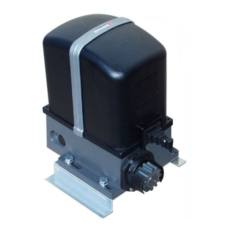
MATRIX range is the new Proteco's electromechanical rack-driven motor generation designed to automate sliding gates in residential, block and
industrial areas.
Any other use than that described is to be considered improper and prohibited.
All models grant the mechanical locking of the gate with an irreversible gear system; it is therefore not necessary to install any type of lock.
MATRIX works by electricity, in case of power cut the motor can be manually unlocked using a special lever system protected by key.
Matrix 2500 Matrix 1800 Matrix BLDC Matrix High Speed
Power supply 230 V 50/60 Hz 230 V 50/60 Hz 230 V 50/60 Hz 230 V 50/60 Hz
Motor voltage 6 A 4,5 A 4,5 A 3 A
Start up current 2,5 A 2 A 1,4 A 1,3 A
Rated current 230 V 50/60 Hz 230 V 50/60 Hz 48 V dc 48 V dc
Rated power 550W 500W 350W 300W
Start up capacitor 25 µF 30 µF - -
Standard capacitor 25 µF 20 µF - -
Start up thrust 2000 N 1400 N 1600 N 1400 N
Rated thrust 1100 N 900 N 1000 N 700 N
Thermal cut off 150°C 150°C - -
Max. opening speed 11 m/min 11 m/min 13 m/min 20 m/min
Max. leaf weight 2500 Kg 1800 Kg 2500 Kg 1800 Kg
Duty cycle 50% 50% 80% 80%
Operating temperature -30° C ÷ + 55° C -30° C ÷ + 55° C -30° C ÷ + 55° C -30° C ÷ + 55° C
IP rating 44 44 44 44
Limit switch type Mechanical/
Magnetic
2.2 Technical features
Mechanical/
Magnetic
Mechanical/
Magnetic
Mechanical/
Magnetic
Fuse 8A 8A 5A + 30A@48V 5A + 30A@48V

4MATRIX - rev. 1.1_09_2020
1 2
3
4
5
6 7
227 mm361 mm
360 mm
2.3 Content
DESCRIZIONE CODICE QUANTITÀ
1Gearmotor 1
2Release key FLC2722 2
3Ground plate MPIS06 1
4Wires membrane MPC06 1
5Anchor screws Grower M10 MRO10EZ 4
5Washer Ø 10 8
54,2x13 self-threading screws MVI4213DI 2
6Anchor screws i M10 MTRF10185Z 8
6Bolt M10 + Washer M10 MDAM10Z 4
6Washer M10 MRO10Z 8
7Limit switch cam LH MSLF01S 1
7Limit switch cam RH MSLF01D 1
7Dowel M6x10 MGR0610Z 4
2.4 Dimensions
Matrix 2500/
Matrix BLDC
Matrix 1800 Matrix High
Speed
Gate weight Duty cycle rate Duty cycle rate Duty cycle rate
600 Kg 100 100 100
From 600 to 1000 80 70 70
From 1000 to 1500 70 50 50
From 1500 to 1800 50 30 30
From 1800 to 2500 40 - -
Matrix 2500 Matrix 1800 Matrix BLDC Matrix High
Speed
Gate length (m) Max. Cycles/
Hour
Max. Cycles/
Hour
Max. Cycles/
Hour
Max. Cycles/
Hour
Up to 6 28 28 40 58
From 6 to 10 14 14 28 40
From 10 to 12 12 12 22 32
From 12 to15 8 - 15 20
From 15 to18 - - 10 -
2.6 Duty cycles
The calculation of cycles refers to a gate of standard length, installed
according to the standards in force, free from mechanical and/or
accidental friction, with an outside temperature of 20 ° C, as per EN
60335-2-103 regulations.
The number of working cycles depends very much on the length
and weight of the gate, as well as the Matrix model choosen for the
installation.
Table 1: Gate Length
Table 2: Reduction of duty cycle rate according to gate weight
Example:
Gate length 10 m, gate weight 1500Kg, Matrix 2500
14 x 0,7 (70%) = 9,8
Approximately 10 cycles per hour
In addition, there may be other factors that can affect the shelf life
of the product.
Factors may vary depending on the environment in which the automation
is installed.
2.7 Life line
The life of the gearmotor may be affected by multiple waste factors.
The life expectation can be calculated using the criteria outlined in
the below table.
In order to get the waste rate add together all values that comply
with the installation scenario and according accessories.
ATTENTION:
If the waste rate obtained is beyond 10, move to a superior
versioninordertofullltheexpectedperformances.
Matrix
2500
Matrix
1800
Matrix
BLDC
Matrix
High
Speed
Normal operation frequently cut
due to obstacle
1 1 1 1,5
Seaside areas 1 1 1 1
Sandy and/or dusty areas 0,5 0,5 0,5 0,5
Outside temperatures often beyond
40° or below 0°
0,5 0,5 0,5 0,5
2.5 Limit switches
Picture 1: Mechanical limit switch Picture 2: Magnetic limit switch

5
Gate weight Matrix 2500/
Matrix BLDC
Matrix High Speed/
Matrix 1800
Up to 600 Kg 0,5 0,5
From 600 to 1000 1 2
From 1000 to 1500 2 3
From 1500 to 1800 3 4
From 1800 to 2500 4 -
Gate length Matrix 2500/
Matrix BLDC
Matrix High Speed/
Matrix 1800
Up to 6 m 0,5 0,5
From 6 to10 1 1
From 10 to 12 1,5 1,5
From 12 to 15 2 2,5
From 15 to 18 3,5 -
Follow the waste rate line of the graph to get the estimated duty
cycles.
Duty cycles obtained may be compromised if the maintenance plan
is not carefully respected.
Duty cycles are determined on the base of design analysis, project
calculations and tests carried out at factory.
Therefore the duty cycles achieved are a mere estimation.
CYCLES
WASTE RATE
ASYNCHRONOUS BRUSHLESS
3. INSTALLATION
3.1 Introduction
Matrix must be installed by qualied personnel, complying
with law regulations and instructions contained in this manual.
For a proper installation, strictly follow the following
procedure, respecting the below chronological order:
• Prepare a strong basement using ferro concrete.
• Fix the gearmotor to ground.
• Fit the rack and the according limit switches.
• Fit safety devices (sensors, blinker, safety edges ....)
3.2 Preliminary checks
Before proceeding to installation, it is necessary to double check
the good condition of every component and make sure the site is
suitable for installation purposes.
• All components must be integral and suitable to use.
•Make sure the installation site complies with system’s dimensions.
• Make sure the concrete basement grants stability and solidity.
• Make sure the area around the system is clear enough to allow
eazy and safe manual operation.
• Make sure gate features are suitable to automate.
• Make sure weight, dimensions and gate features are suitable
to the model you have choosen.
•Make sure cogwheel case doesn't hit against any fixing points
of the gate (as screws, bolts, gate's wheels).
•Make sure the gate area is fitted with ground stops both in
opening and closing.
•Make sure the installation area grants fixing stability and
solidity.
• Make sure the gate is mechanically free of friction.
•Make sure the automation fixing area is compatible with the
dimensions of the ground plate and that there is sufficient space
to carry out manual operation easily and safely.
• Make sure the automation positioning area is not subject to
flooding; possibly install the automation raised from the ground.
•If the system is installed in areas where vehicles transit, it is
advisable to provide adequate protection against accidental
impacts.
• Make sure the electric circuit is connected to a state of the
art safety grounding.
•Make sure the fixing surfaces of the photocells are flat and
allow correct alignment between transmitter and receiver.

6MATRIX - rev. 1.1_09_2020
E
D
B
C¹
C
A
500 mm
300 mm
400 mm
3.3 Electric layout
Picture 3: Electric layout
Refer to next chapter.
3.4 Wires features
Cables necessary for the installation of the system (not
included) may vary according to the quantity and type of
accessories and devices fitted.
230V 24V
ASafety edge 2x0,5 2x0,5
BPower supply 2x1,5+T 2x1,5+T
CPhotocells Rx 4x0,5 Rx 4x0,5
C¹ Photocells Tx 2x0,5 Tx 2x0,5
D Key switch 2x0,5 2x0,5
EBlinker 2x0,5 2x0,5
3.5
Basement preparation
It is absolutely key to build a solid concrete basement (at least
EN206 C25/30 proof).
Basement dimensions must be no less than 500x300mm and no
less than 400mm deep.
We recommend to consider an extra concrete surface of 100 mm
all around the basement. (Picture 4).
Picture 4: ferro concrete basement
Picture 5: basement section
Pay attention while arising the basement, since the concrete work
cannotimpedetostudthexingscrews.
Do not forget wirings! While preparing the concrete basement
keep a duct of the proper dimension to connect the main power
and any possible additional devices.
Drive the wires guide through the right hole of the ground plate and
keep it oriented towards the property.
Make sure ground plate is properly levelled. (Picture 6)
PROPERTY VIEW
Picture 6:
Basement and ground plate
Picture 7: Top view

7
Screw nut and washer M10 to the anchor bolts, keeping the same
distance for all of them, in order to create a balanced support for
the ground plate.
Put anchor bolts M10 into holes, then tighten washers and bolts
M10 as shows Picture 10.
ELECTRIC
CABLES
SLOT
Picture 8: Gearmotor top view
Cast the concrete and, before setting begins, put the ground plate
in the center, leaving a margin of 40/60mm; ground plate has to be
aligned to the gate and properly levelled.
Wait for the concrete to set completely.
ATTENTION: Keep the ground plate surface and anchor
bolts as clean as possible (screen the anchor bolts).
Leave electrical cables at least 30-50cm longer to allow easy
connection to the control unit.
MATRIX - rev. 1.1_09_2020
3.6 Fixing on ground
Loose washers and bolts M10 screwed on the ground plate.
Proceed to remove Matrix's cabinet.
Lay the gearmotor on the ground plate.
Match anchor bolts protruding from the ground plate to the aluminium
base slots.
Fix the gearmotor to ground plate using flat washers M10, Grower
washers and bolts M10 provided in the ttings bag.
Pay attention while xing, cogwheel must be oriented towards the gate.
Attention! Drive electric cables through the aluminium base and
keep them away from components that may warm up (as motor,
transformer, etc etc).
Cut the membrane keeping an extra margin of 3 cm from ground
plate edge and t the cables for safety devices and power supply
connection.
Figura 11:
Picture 9:
Ground plate view
Picture 10: Anchor screws view
It is possible to adjust the heigth of the aluminium base calibrating
the 4 screws 10x50 and springs (this will be necessary only if Matrix
serves as replacement of a previous installation, refer to picture 11)
Heigth can be adjusted up to max. 19mm (without washer).
Unlock the gearmotor and set it to manual operation mode.
3.7 Manual operation
Switch the power off and release the gearmotor using the lock
barrel positioned on the alluminium base.
Lift the plastic tang to accede to the lock (Picture 12).
Plug the key in and turn it counter clockwise.
Pull the release lever completely to full opening (90°), (Picture 13).
Now you can move the gate manually.
ATTENTION: Be carefull, the gate may accidentally move.

8MATRIX - rev. 1.1_09_2020
91 mm
> 5 mm
22
11
÷÷
To lock the gearmotor back, put the release lever to its original
closing position and turn the key clockwise (Picture 12).
Remove the key from the barrel and pull down the plastic tang.
Move the gate to restore the lock system.
Power the gearmotor.
Picture 12- Lock barrel
Picture 13- Manual release
3.8 Rack installation
3.8.1 B102 steel rack - type M4 12x30mm - 1m length
ATTENTION:
Fit the rack as shown in the below picture.
Manually move the gate to opening position.
Fit the three bolts to the rack in the centre of each slot (Picture 14).
Rack has to be aligned to the gate.
While positioning the rack, keep a small gap between rack and
cogwheel of 1/2mm and level. Weld the rst bolt to the gate.
Move the gate manually making sure the rack properly matches the
cogwheel, then weld the second and third bolt.
Place another rack piece beside, using another one underneath for
calibration. See Picture 15
Picture 14- Rack installation
Picture 15- Rack calibration
Move the gate manually and weld the three bolts.
Close the gate manually for about 0,5 m, and join the second rack
piece to the rst one, keeping match to the cogwheel.
Make sure rack is properly levelled and x.
Repeat the same procedure for the whole gate's length.
The last rack piece may exceed the gate length: in this case add a
bracket as gate extension and as rack support (Picture 16).
Picture 16: - Extension bracket
ATTENTION: Make sure the gate
regularly reaches mechanical
ground stops keeping match
between rack and cogwheel.
Make sure as well the gate is
free of friction points during
cruising.
IMPORTANT: Avoid the gate
overloads the gearmotor.
Keep a small gap between the rack
and the cogwheel (Picture 17).

9
3.9 Limit switches installation
3.9.1 Mechanical limit switches
Picture 19: Cam installation on rack
Picture 18
Once the motor position is determined, adjust limit switches
accordingly. (Picture 18)
•
Manually close the gate and keep a margin of 3 cm before
reaching the closing mechanical stop.
•
Fit the two dowels to the limit switch cam.
•
Lean the cam and slide until the limit switch is activated.
•
Tighten the dowels to secure the cam to the rack.
•
Manually move the gate to opening position and repeat the same
procedure.
•
Take the dowels and fix the limit switch cams.
CLICK
CLICK
Picture 20
Picture 22
Once the motor position is determined, adjust limit switches
accordingly. (Picture 22)
• Manually close the gate and keep a margin of 3 cm before
reaching the closing mechanical stop.
• Fit the two dowels to the closing limit switch cam.
•Lean the cam and slide until the limit switch is activated.
• Tighten the dowels to secure the cam to the rack.
• Manually move the gate to opening position and repeat the
same procedure.
•Take the dowels and fix the limit switch cams.
Picture 23: Cam installation on rack
3.9.2 Magnetic limit switches
Picture 24
Picture 25
Once the installation of the limit switch cams has been completed,
proceed to general test. (Pictures 24/25).
This procedure guarantees the correct functioning of the automation
and preserves the good mechanical condition of the gate.
ATTENTION: The magnetic limit switch is activated when
approaching the magnetic area.
Leave the gear and control unit visible to double check the
good operation of the system.
ATTENTION: Remove any exceeding rack.
Picture 21
Once the installation of the limit switch cams has been completed,
manually move the gate in opening and closing and check
that cams always activate the limit switch without reaching
the mechanical stop. (Pictures 20/21)
This check guarantees the correct functioning of the automation
and preserves the good mechanical condition of the gate.
ATTENTION: Remove any exceeding rack.
RH LIMIT SWITCH
LH LIMIT SWITCH
RH LIMIT SWITCH
LH LIMIT SWITCH

10 MATRIX - rev. 1.1_09_2020
Picture 26: Wirings
3.10 Wirings
The power connection must be performed by experienced
qualiedpersonnel,infullcompliancewith laws,rules
and regulations.
Insert the electrical cables into the supplied cable gland, breaking
through the membranes and place the cable gland in the appropriate
seat on the base of the gearmotor.
Connect all power and grounding cables to the appropriate terminal
block located near the symbol .
Picture 27: Wirings terminal block
LIVE EARTH NEUTRAL
3.11 MasterandSlaveconguration
Picture 28: TWIN mode - full opening
Picture 29: TWIN mode - pedestrian/partial opening
3.12 General test
Before starting the general test, be sure programming has been
carried out (Refer to chapter "3.5 Start Up" of the control unit
manual).
Once mechanical installation and electrical connections have
been completed, power the automation and proceed with a
careful test of the gearmotor, accessories and safety devices
connected.
Important! Programming procedure must be repeated
every time anything concerning the gate has been changed
(speed, weight, rail, wheels ...)
Most importantly, check that opening and closing limit switches
work correctly, stopping the gearmotor before it reaches
the mechanical stops.
After powering the gearmotor, manually move the leaf to
opening and closing position and check that LO (Opening limit
switch) and LC (Closing limit switch) are displayed on the
control unit before reaching the mechanical stop.
Make sure both messages are properly displayed.
Deliver the end user chapter of this manual to the customer
and instruct him how the automation works and how to use it.
3.13 Cabinet installation
Once both mechanical and electrical installations are
completed, proceed to fit the cabinet.
Lean the cabinet onto the alluminium base, just put a little
pressure on the upper side.
Use the two screws 4,2x13 to fix the cabinet, as show Pictures
30 and 31.
Picture 30: Matrix section view
PARTIAL/PEDESTRIAN start command is performed only by
MASTER motor.
The TWIN function allows to synchronize two mirror sliding gates
as shows Picture 28.
For more details refer to chapter "TWIN mode"
.

11
Picture 31
CABINET
SCREW
4,2X13
O.R.
3,68x1,78
4. MAINTENANCE
Attention! Maintenance service must be carried out
by qualifiedtechnical personnel,infullcompliancewiththe
safetystandards required by the laws in force.
Maintenance has to be carried out every six months.
Regular maintenance is required to keep the automation safe and in
good operation over time.
In order to proceed to maintenance service, follow the below
checks:
• Turn the POWER OFF.
• Check screw connections are properly tightened.
•
•
Check the condition of moving components: cogwheel, rack
and gate parts.
Proceed to replace the wasted parts.
Turn the POWER ON and proceed to the expected tests
outlined in the chapter.
• Lock the gearmotor back and proceed to test.
4.1 Release system test
To check the efciency of the release system, perform the following
checks.
Disconnect any power source, use the supplied key to release the
lock barrel on the aluminium base.
Pull the release lever and move the gate manually to check proper
operation.
Gate leaf must slide freely during the whole cruise.

12 MATRIX - rev. 1.1_09_2020
DATE NOTES INSTALLER'S SIGNATURE END USER'S SIGNATURE

13
5. END USER GUIDELINES
The following pages contain important information for your safety
and for complying with standing safety regulations.
Keep this manual for future reference.
5.1 Safety tips
Keep children under 8 away from the system.
Children over 8, people with reduced physical or mental
abilities, or lacking experience, may only use the automation
under supervision, or if they have been instructed on how to
use safely the system and have understood the related
dangers.
This product was designed and built exclusively for the
intended use indicated.
Any other use could compromise the integrity and safety of
the product and should be avoided.
Do not access, for any reason, the internal parts of the
automation: it may be dangerous and components can only
be repaired or replaced by qualied personnel.
Do not start transmitters or other command devices unless
the area is visible and clear from danger.
Do not allow children play within the automation area.
5.2 Manual operation
Torelease the gearmotor use the lock barrel positioned on the
aluminium base.
Lift the plastic tang to accede to the lock (Picture 32).
Plug the key in and turn it counter clockwise.
Pull the release lever completely to full opening (90°), (Picture 33).
Now you can move the gate manually.
ATTENTION: Be carefull, the gate may accidentally move.
To lock the gearmotor back, put the release lever to its original
closing position and turn the key clockwise (Picture 32).
Remove the key from the barrel and pull down the plastic tang.
Move the gate to restore the lock system.
ATTENTION: put the gate exactly in the same previous
position, or switch the power off during 5/10 seconds and then
turn the power on again.
ATTENTION: store key and installation manual in a safe place
for future reference.
5.3 Maintenance
To keep the automation safety and in good operation over time,
it is advisable to schedule a periodic maintenance plan with the
installer, or at least report any anomalous behaviors that may
require inspection.
In case of malfunctions it is advisable to contact the installer
who carried out the whole installation, rather than others.
Periodic maintenance and repairs must be reported by the installer
and the owner must keep them safe and available for future
reference.
End user may only take care of photocells and automation housing
cleaning.
5.4 Disposal
5.4.1 Disposal of the system
Any part of the system, including devices such as remote controls,
must be disposed in compliance with current legislation, as they
may be harmfull for the environment.
Most of the materials used are similar to solid urban waste and
can be handled accordingly.
They can be recycled through separate collection and disposed in
authorized centers.
Other components (electronic boards, batteries, etc.) may instead
contain polluting substances.
They must therefore be removed and delivered to companies
authorized for their recovery and disposal.
Before proceeding, it is always advisable to check the specic
regulations in force.
5.4.2 Disposal of packing
Packaging components (cardboard, plastics, etc.) are sare similar
to solid urban waste and can be handled accordingly without any
difculty, simply by carrying out separate collection for recycling.
Before proceeding, it is always advisable to check the specic
regulations in force.
DO NOT POLLUTE THE ENVINRONMENT!
Some components may contain polluting or dangerous
substances, if dispersed they could affect the environ-
ment and human health.
Picture 32- Lock barrel
Picture 33- Manual release

Proteco S.r.l. Via Neive, 77
12050 CASTAGNITO (CN) ITALY
Tel. +39 0173 210111 - Fax +39 0173 210199
info@proteco.net - www.proteco.net
This manual suits for next models
5
Table of contents
Other Proteco Gate Opener manuals

Proteco
Proteco SIMPLY User manual

Proteco
Proteco Diamond 3Ti User manual

Proteco
Proteco leader ta Guide

Proteco
Proteco leader ta Guide

Proteco
Proteco Shark Guide

Proteco
Proteco Advantage Guide

Proteco
Proteco Mover 4 Guide

Proteco
Proteco ASTER NEW User manual

Proteco
Proteco Shark New Guide

Proteco
Proteco MEKO User manual