manuals.online logo
Brands
  1. Home
  2. •
  3. Brands
  4. •
  5. Proteco
  6. •
  7. Gate Opener
  8. •
  9. Proteco Shark Guide

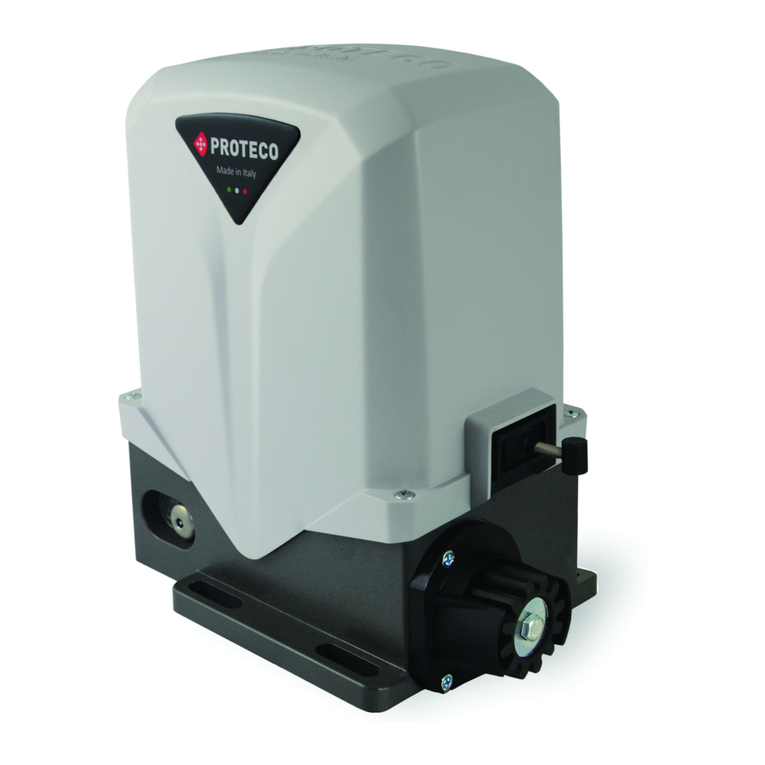
Proteco Shark Guide

13_2008
Shark
PRODOTTI
PRODUITS
PRODUCTS
ERZEUGNIS
PRODUCTOS
Manuale d’Installazione e d’Uso
Manuel d'Installation et Utilisation
Installation and use manual
Handbuch der Installation und des Gebrauchs
Manual de Uso e Instalación
AUTOMAZIONI PER CANCELLI A BATTENTE
AUTOMATISMES POUR PORTAILS A BATTANTS
AUTOMATION FOR SWING GATES
AUTOMATISIERUNG FÜR FLÜGELTORE
AUTOMATISMOS PARA BATIENTES
Proteco S.r.l. Via Neive, 77 - 12050 Castagnito (CN) ITALY
Tel. +39 0173 210111 - Fax +39 0173 210199 www.proteco.net - info@proteco.net
SCHEMA FUNZIONALE - SCHÉMA DE FONCTIONNEMENT
OPERATIONAL DIAGRAM - FUNKTIONSPLAIN - ESQUEMA FUNCIONAL
160
320
380
65
24V 230V OIL
24V dc
0,8 - 1
60 W
-------
230V ~ 50 Hz
1,2 - 1,7
300 W
10 µF
230V ~ 50 Hz
1,2 - 1,7
300 W
10 µF
200 N
66
1400 g/m
2,50 m 3,00 m 3,00 m
200 Kg 300 Kg 300 Kg
110° 110° 110°
15” 15” 15”
90% 50% 60%
300 N
66
1400 g/m
300 N
66
1400 g/m
-------- 150° 150°
-25° - +70°C -25° - +70°C -25° - +70°C
mt= Lunghezza anta
Longueur du portail
Leaf lenght
Torflügelbreite
Dimensiones hojas
Kg= Peso anta
Poids du portail
Leaf weight
Torflügelgewicht
Pesa de la hoja
Kg
mt
2,5 3,0 3,5
200
300
400
500
600
_
_
_
_
_
_
_
_
_
Il diagramma è valido con tutta elettronica PROTECO
Ce diagramme n’ast valable que pour une installation avec une électronique PROTECO
The diagram is efective with the whole of PROTECO electronics
Das diagramm ist gültig mit PROTECO elektronic
El diagrama es válido si se utiliza electrónica PROTECO
1 Motoriduttore -
2 Centrale elettronica -
3
4
5
6
7
Motoreducteur - Gear motor -Antrieb - Motorreductor
Centrale électronique - Electronic control unit - Elektroschrank - Central eléctronica
Fotocellule - Photocellules - Photocells - Fotozelle - Fotocélulas Rx
Tx
Antenna -Antenne -Aerial -Antenne -Antena
Ricevitore radio - Récepteur radio - Radio Receiver - Funkempfänger - Receptor radio
Lampeggiatore - Clignotant - Warning light - Blinkleuchte - Luz Intermitente
Selettore a chiave - Contacteur a clé - Key contactor - Schlüsselschalter Selector de llave
--
A 3 x 1,5+T
B 2 x 1,75+T
F 2 x 0,75
C 2 x 0,75
2 x 0,75
_
C¹ 4 x 0,75
D
6
3
3
3
1
1
2
AA
F
D
C¹
C¹ C
C
7
3
5
4
Alimentazione - Alimentation - Power supply - Anschluss - Alimentaci n
Assorbimento - Consommation - Absorption - Stromaufnahme - Absorción de línea
Potenza - Puissance moteur - Motor power - Motorleistung - Potencia
Condensatore - Condensateur - Capacitor - Kondensator - Condensador
Protezione termica - Protection thermique - Thermic protection
Thermoschutz - Protecci n térmica
Spinta max - Poussée - Maximum thrust - Drehmoment - Empuje máx
Grado IP - Classe IP - IP level - Schutzart IP - Grado de protección IP
Giri motore - Vitesse moteur - Motordrehzahl - Rotación del motor
Temperatura di funzionamento - Température de service - Working temperature
Temperaturbereich - Temperatura de servicio
Lunghezza max anta - Vantail maximum - Leaf’s maximum length
Max. Flügelgellänge - Longitud máx. hoja
Peso max anta - Poids maximum du vantail - Leaf-s maximum weight
Max. Flügelgewicht - Peso máx. hoja
Angolo max di apertura - Angle max d’ouverture - Maximum opening
Max. Öffnungswinkel - Ángulo máx. de abertura
Tempo di apertura 90° - Temps d’ouverture 90°- 90° opening time
Öffnungszeit - Velocidad angular 90°
Ciclo di lavoro - Cycle de travail - Duty cycle - Benutzungshäufigkeit - Ciclo de trabajo
ó
ó
Revolutions speed -
CARATTERISTICHE TECNICHE - CARACTERISTIQUES TECHNIQUES
TECHNICAL FEATURES - TECHNISCHE ANGABEN - CARACTERISTICAS TECNICAS
65 65
01 n°1 Motoriduttore - Gear-motor - Motoréducteur - Getriebemotor - Motorreductor
02 n°1 Cassetta di protezione - Protection box
n°1 Coperchio - Cover
n°1 Leva di sblocco - Release lever
n°1 Leva di trasmissione - Trasmission lever
n°1 Condensatore -
n°1
n°4
n°2 Rondelle 3x30 - Washer 3x30
Viti a brugola TCEI 6X12 zinc. -Screw TCEI 6X12
10 n° Sfera inox Ø25 / Inox ball Ø25
11 n° Viti 6x16 per fissaggio coperchio - Screw 6x16
n°1 Manuale d’installazione ed uso - Installation and use manual
Manuel d’installation et utilisation - Handbuch der Installation und des
Gebrauchs - Manual de Uso e Instalacion.
03
04
05
06 Condensateur - Capacitor - Motorkondensator Condensador
07 Chiave di sblocco - Realise key - Clé de deveuillage
Freisetzung des Schüssel - Llave de desbloqueo
08 Dadi M12 per fissagio motore - M12 nuts - Ecrous M12 - Verzinkte
Schraubenmutter M12 - Tuercas M12
09
Fig. B
110°
Fig. A
90°
COMPOSIZIONE - COMPOSITION - COMPOSITION - KOMPOSITION - COMPOSICION
Fig. C
Centrale
e aC ntr le
2
1
Fig. D
Scavo di fondazione
Fig. N
Fig. I
Chiave di sblocco
Clé de deveuillage
Realise key
Freisetzung des Schüssel
Llave de desbloueo
Fig. M
Posizione dei motori nelle cassette
Positionament des moteurs dans les caisson
Insert the motor in the box - Getriebemotors
Positionamento de los motores las casas
DxSx
Fig. H
L3
L2
L1
F2
Fig. G
L1
Fig. F
Dado M 12
F2F1
Fig. E
Fig. L
P2 P1
C
01
02 03
04
05
07 10
11
06
09
08
INTERNO -
- -
INTÉRIEUR
INSIDE INTERIOR INNENSEITE
ESTERNO - -
EXTÉRIEUR - OUTSIDE
EXTERIOR AUßENSEITE
CRITERI DI SICUREZZA DETERMINAZIONE POSIZIONE
1Prima d’iniziare qualsiasi operazione d’installazione è assolutamente Scegliere in base al tipo di struttura e di apertura che si vuole, l’esatta
necessario leggere tutto il presente manuale. posizione del gruppo motore seguendo le indicazioni:
2Verificare che le prestazioni dell motoriduttore acquistato corrispondano CANCELLO FISSATO AL CENTRO DEL PILASTRINO (FIG. A)
alle vostre esigenze d’ installazione. In questo caso l’angolo massimo di apertura del cancello è di 90°.
3Inoltre verificare che: CANCELLO FISSATO SULLO SPIGOLO DEL PILASTRINO (FIG. B)
- Le cerniere del cancello siano in buono stato e perfettamente ingrassate. In questo caso il cancello può aprire con un angolo maggiore di 90°. (max
- Il cancello sia dotato di fermi meccanici in apertura ed in chiusura. 110°)
CONSIGLI PER L’INSTALLAZIONE CASSETTA DI PROTEZIONE (Fig. D)
Collegamenti: - Praticare nel terreno nella posizione stabilita, uno scavo di Fondazione
• Vedere “Schema funzionale” e fare riferimento agli schemi della di dimensioni tali da poter contenere la cassetta di Protezione.
centrale di comando. - Posizionare la Cassetta di Protezione all’interno dello Scavo di
• Tutti i collegamenti devono essere effettuati in assenza di Fondazione, assicurandosi che il perno sia allineato al cardine dell’anta
alimentazione. del cancello, mantenendo una distanza di 65 mm dal centro cardine al
• Prevedere un dispositivo di sezionamento onnipolare nelle vicinanze pilastrino. (Fig. E)
dell’apparecchio (i contatti devono essere di almeno 3 mm) - Eseguire in prossimità del foro F1 della cassetta di protezione uno
Proteggere sempre l’alimentazione per mezzo di un interruttore scarico per l’acqua, che eviti, nella fondazione il ristagno e successive
automatico da 6A, oppure per mezzo di un interruttore monofase da 16A ossidazioni. (Fig. F)
completo di fusibili. - Prevedere il percorso dei cavi elettrici attraverso il foro F2 della cassetta
• Le linee di alimentazione ai motori, alla centrale e le linee di di Protezione, secondo“Schema funzionale”. (Fig. N)
collegamento agli accessori devono essere separate onde evitare - Interrare la cassetta di Protezione utilizzando del calcestruzzo,
disturbi che potrebbero generare mal funzionamenti dell’impianto. curandone la messa in bolla e la corretta posizione del bordo superiore.
• Qualsiasi apparecchiatura (di comando o sicurezza) eventualmente
asservita alla centrale deve essere libera da tensione (contatti puliti). MOTORIDUTTORE
Parti di ricambio: - Posizionare il motoriduttore sul fondo della cassetta di Protezione e
• Utilizzare solamente parti di ricambio originali. fissarlo ai perni filettati con gli appositi dadi M12. (Fig. F)
Modalità d’installazione: - Posizionare la leva “L1”leva di sblocco sul perno uscente della
• Per un uso proprio del prodotto e per escludere ogni possibilità di cassetta. (Fig. G)
danneggiamenti a persone, animali o cose, fare riferimento al foglio - Montare la leva ”L2” leva di Trasmissione sulla leva “L1”. (Fig. H)
"Generalità" allegato che fa parte integrante del presente manuale. - Unire la leva “L2” alla leva “L3” leva albero uscita (uscente dal motore)
• L'impiego di questa apparecchiatura deve rispettare le norme di infilando i due perni negli appositi fori e fissandoli con vite SPEI M6X18.
sicurezza vigenti nel paese d’installazione oltre alle norme di buona (Fig. H)
installazione. - Chiudere la cassetta di Protezione, con il coperchio fissando le
Garanzia: apposite viti M6x18 TPSCEI in dotazione.
• La garanzia fornita dal costruttore decade in caso di manomissione, - Posizionare l’anta del cancello e la leva “L1” leva di Sblocco uscente
incuria, uso improprio, fulmini, sovratensioni o utilizzo da parte di dalla cassetta di Protezione in modo che siano perfettamente allineate
personale non professionalmente qualificato. (in asse). Fissarle mediante saldatura.
• Fa inoltre decadere qualsiasi diritto alla garanzia: non rispettare le
istruzioni riportate sui manuali allegati ai prodotti. FERMI MECCANICI
L'applicazione anche di un solo particolare in modo non rispondente alla Aquesto punto occorre posizionare i fermi meccanici per effettuare il fermo in
legislazione vigente o l'utilizzo di parti di ricambio non congeniali e/o non chiusura e in apertura dell’anta.
espressamente approvata dalla ditta costruttrice.
• Il costruttore non può considerarsi responsabile per eventuali danni CANCELLO CHE APRE ALL’ESTERNO
causati da usi impropri ed irragionevoli. Nel caso il cancello apra verso l’esterno è possibile posizionare il motore
all’interno della cassetta di Protezione ruotandolo di 180°.
SEQUENZA DI INSTALLAZIONE
1Prima d’iniziare la messa in opera, effettuare sull’installazione l’analisi SBLOCCO DELL’ATTUATORE
dei rischi facendo riferimento al foglio “Generalità“ che fa parte - Togliere l’alimentazione elettrica.
integrante del presente manuale, riempire la tabella tecnica ed - Inserire la chiave di sblocco in dotazione nell’apposito foro sulla leva di
eliminare i rischi rilevati. Sblocco e girare in senso orario (anta a sinistra) e antiorario (anta a
Nel caso in cui vi siano rischi residui, prevedere l’installazione con destra), liberando così la trasmissione (Fig. I)
sistemi di sicurezza e completamento. Togliere la chiave di sblocco ed eseguire la manovra manualmente.
2Verificare le norme di sicurezza citate nei “Criteri di sicurezza”. - Aquesto punto è possibile aprire e chiudere manualmente il cancello.
3Identificare tutti i componenti. - Per reinserire la trasmissione, è sufficiente portare l’anta nella posizione
4Identificare l’esatta posizione del GRUPPO MOTORE. di partenza (l’innesto è automatico).
5Praticare sul terreno nella posizione stabilita uno scavo di Fondazione. - Ripristinare l’alimentazione elettrica.
6Posizionare la cassetta di Protezione all’interno dello scavo di
Fondazione. DISPOSITIVO PER APERTURA 180° (A 008)
7Prevedere uno scarico per l’acqua. Il dispositivo viene utilizzato in casi particolari, per rendere possibili aperture
8Stendere i cavi come da “Schema funzionale ” fino a 180°.
9Posizionare e fissare il motoriduttore all’interno della cassetta di Per una corretta messa in opera del dispositivo agire come segue:
Protezione. - Individuare sul motoriduttore il pignone P1. (Fig. L)
10 Montare il gruppo di leve per il movimento del cancello. - Montare la leva P2 sul perno uscente dalla Cassetta di Protezione.
11 Chiudere la cassetta di Protezione. - Inserire la catena di Trasmissione “C” sulle ruote dentate, tenderla ed
12 Posizionare e fissare l’anta del cancello. agganciarla.
13 Collegare la centrale e tutti gli accessori. - Ingrassare la catena di Trasmissione.
14 Programmare il ricevitore radio. - Chiudere la Cassetta di Protezione con il coperchio fissandolo con le
15 Eseguire la programmazione dei “Tempi di funzionamento”. apposite viti M6x18 TPSCEI in dotazione.
In caso di mal funzionamento, fare riferimento alla tabella “Anomalie e - Posizionare l’anta del cancello e la leva L1 uscente dalla Cassetta di
Consigli”. Protezione in modo che siano perfettamente allineate (in asse).
NEL CASO IN CUI NON RIUSCIATE A TROVARE ALCUNA SOLUZIONE Fissarle mediante saldatura.
TELEFONAREALPIÙ VICINO CENTRO DIASSISTENZA. - Ripetere la stessa operazione per l’altra anta.
ATTUATORE BLOCCATO
I motoriduttori interrati con leva di trasmissione a movimento sono forniti in
versione bloccata.
L’elettroserratura deve essere installata sull’anta che si apre per prima e
deve essere collegata ai relativi morsetti della centrale.
POSIZIONE DELL’ELETTROSERRATURA (Fig. C)
Posizione 1: Posizionamento in orizzontale con aggancio con anta che
si chiude per prima (in questo caso è necessario utilizzare il paletto
modello RT15 sull’anta che si chiude per prima)
Posizione 2: Posizionamento in verticale con aggancio a terra.
(in questa posizione l’utilizzo del paletto non è indispensabile)
Ricordarsi di eliminare la serratura meccanica preesistente o quanto meno
renderla inattiva bloccando lo scrocco in posizione aperta ed eliminare tutti i
paletti di chiusura.

SAFETY CRITERIA
1 Attention: before beginning anykind of procedure of installation is LOCKED ACTUATOR
absolutely necessary to read all this manuall. The gear motor may with trasmission and drive lever be either locked.
2Test/Control that the perfornces of the actuator auswer to your The electric lock must be installed on the wing that opens first and must be
installation needs. connected with the terminal board of the control unit.
3Besides control that: Position of the electric lock: (Fig. C).
• The gare hinges are in good conditions and perfectly fattened. Position 1: Lock between the wings.
• The gate has mechanicall stops in the opening and the closing. (in this case is necessary to use the bolt RT15 on the second wing)
Position 2: Lock in the floor.
INSTALLATION ADVICE (in this case the utilisation of the bolt is not essential)
Connections: In any other case, we suggest the locked actuator.
• See the “Operational Diagram” and refer to the control central scheme. In this case remenber to remove the lock or at least block the lock in opening
• The adjustment must be effected when the device has no power supply. position and take away all the bolts of lock.
• Foresee a omnipolar breaking device near to the apparatus (the contact
must measure at least 3 mm). DETERMINATION OF FIXING MEASURES
Always protect the power supply using a 6A automatic switch, or a 16A Following the instructions, choose the exact position of the gear motor
single-phase switch fises. paying attention to the structure and the opening you want.
• The power supply lines the motors, to the control unit and the connection GATE FIXED IN THE MIDDLE OF THE PILLAR (FIG. A)
lines to the outfits must be sepated to avoid troubles which could In this case the maximal opening corner of the gate is 90°.
generate problems in the installation working. GATE FIXED ON THE EDGE PILLAR (FIG. B)
• Any outfits (of control or safety) eventually connected to the control unit In this case the gate can open with a corner superior to 90°. (max 110°)
must be tension free.
Spare parts: PROTECTION BOX (FIG. D)
• use esclusively original spare parts. - Make, in the established position, a digging on the ground which can
Installation: cobtain the Protection box.
• In order to correctly use the product and to exclude the possibility of - Put the Protection box into the digging.
injury or damage, refer to the "Generals" page enclosure, which is an Make sure that the pin is aligned with the pivot of the leaf and that you
integrated part of this manual. have respected the distance of 65 mm between the centre of the pivot
• The use of this equipment must be in observance of the safety standards and the piller. (Fig. E)
in force in the country where it is installed, as well as the standards - Make near the holes F1 of the Protection box a discharge for the water
governing proper installation. in order to avoid a possible back water as well as an oxidation of the gear
Warranty: motor. (Fig. F)
• The warranty supplied by the manufacturer becomes void in the event of - Notioe that the electrical cables have to go through the hole F2 of the
interference, carelessness, improper use, lightening damage, power Protection box, as in the “Functional scheme for swing gate”. (Fig. N)
surges or use by unqualified personnel. - Make sure that the Protection box is perfectly horizontal and bury it with
• The warranty will also become void in the event of the following: concrete.
Failure to observe the instructions given in the manuals supplied with the
product. GEAR MOTOR
The application of any part in a manner differing from that provided for - Put the gear motor on the bottom of the Protection box and fasten it
current legislation or the use of spare parts which are unsuitable and/or firmly to the tapping-screw with the right nuts M12. (Fig. F)
not approved by manifacturer. - Install the lever “L1” on the pin which comes out from the box. (Fig. G)
• The manufacturer cannot be held responsible for damages due to - Install the lever ”L2” lever of Transmission on the “L1” ( just installed).
improper or unreasonable use. (Fig. H)
- Juin the lever “L2” to the lever “L3” (coming out from the gear motor) by
INSTALLATION INSTRUCTION SEQUENCE driving thepins into the right pivots and them with screws SPEI M6X18.
1Before the installation, anomalyse the risks referring to the chapter (Fig. H)
“Generalities” of this instructions manual, fill the technic table and - Closed the Protection box, with the cover and fasten it with the right
eliminate the risks a noticed. screw M6x18 TPSCEI.
In case of more risks, foresee the installation with security system. - Aligne both the leaf of the gate and the lever “L1” which comes out from
2Est the security laws of the “Security Criteria”. the Protection box. Fix them all with soldering.
3Control all the components.
4Decide the position where you want to install the gear motor. MECHANICAL STOP
5After deciding the right position tou have to make a digging on the Now it is necessary to put the locks in order to make the openin and in the
Ground. closing of the swing.
6Install the Protection box in the digging on the Ground.
7Foresee a discharge for the water. GATE WITH EXTERNAL OPENING
8Connect the Electrical cables as in the “Operational Diagram” If the gate has an external opening it is possible to put the motor in to the
9Put the gear motor on the botton of the Box and fasten it firmly inside the Protection box moving it of 180°.
protection.
10 Install the levers for the gate movement MOTOR RELEASE
11 Close the Protection box.- Turn off the electricity.
12 Aligne and fix the leaf of the gate. - Put the release key in the correct hole on the release lever and turn the left
13 Connect the central and all the accessoires clockwise, whereas the right leaf in the other direction.
14 Program the radio receptor In this way you will release the transmission. (Fig. I)
15 Pèrogram working times Take out the key and do the emergency manouvre.
In case of badworking, see the “Anomalies and Counsuls” - Now it is possible to open and to close the gate handly.
IF YOU DO NOT FIND ANY SLUTION COLL THE NEATEST ASSISTENCE - In order to re-estabilish the transmission, you have to put the leaf in the
CENTRE. starting position (the clutch is auomatic).
- Re-estabilish the power supply.
DEVICE 180° (A 008)
The device has been applied to particular cases, to allow openings util 180°.
For a correct installation of the device 180°, fallow carefully these
instructions:
- Find out the pinion P1 on the gear motor. (Fig. L)
- Mount the lever with pinion P2 on the pin which comes out from the box.
- put the transmission key “C” on the spur wheel, stretch it and fasten it.
- Grease the chain. Close the box with the cover and fix it with suitable
screws M6x18 TPSCEI.
- Aligne both the leaf of the gate and the lever L1 which comes out from the
box. Fix them all with soldering.
- Repeat the same operation with the other leaf.
CRITERIOS DE SEGURIDAD DETERMINACIÓN POSICIÓN
1Antes de empezar la instalación leer atentamente todo el presetne manual Eligir con respecto al tipo de estructura y de abertura requerida la exacta
2Asegurarse que el rendimiento de este motorreductor correspondan a posición del grupo motor siguiendo las indicaciones:
vuestras exigencias de instalación. CANCELA FIJADA EN EL CENTRO DEL PILAR (Fig.A)
3Además averiguar que: En este caso el angulo máximo de abertura de la cancela es de 90°.
- los goznes sean en buenas condiciones y perfectamente lubricadas CANCELA FIJADA EN LA ESQUINA DEL PILAR (Fig.B)
- la cancela tenga topes mecánicos en abertura y cierre. En este caso la cancela puede abrir por una angulación mayor a los 90°.
(max 110°)
ADVERTENCIAS PARA LA INSTALACIÓN
Conexiones CAJA DE PROTECCIÓN
• Ver “Esquema funcional” y hacer referencia a los esquemas del cuadro - Practicar en el suelo, en la posición establecida, una excavación de
de maniobra. Fundación para poder contener la caja de protección.
• Todas las conexiones tienen que ser efectuadas en absencia de - Posicionar la Caja de Protección dentro de la excavación de fundación,
suministro de corriente. asegurandose que el perno sea alineado al gozne de la hoja de la
• Planear un aparato de seccionamiento omnipolar cerca del dispositivo cancela, manteniendo una distancia de 65 mm del centro del gozne del
(los contactos tienen que ser de 3 mm como mínimo). pilar (fig.E).
Proteger siempre lel suministro de corriente por medio de un interruptor - Practicar cerca del agujero F1 de la caja de protección un tubo de salida
automático de 6A, o por medio de un interruptor monofásico de 16A para el agua para evitar estancación y sucesivas oxidaciones (Fif.F).
completo de fusibles. - Prever el percurso de los cables eléctricos através del agujero F2 de la
• Las lineas de suministros de corriente a los motores, al cuadro y las caja de protección, según el “Esquema funcional ”(Fig. N)
lineas de conexiones a los accessorios tienen que ser separadas para - Soterrar la caja de protección utilizando el hormigón, haciendo cuidado a
evitar interferencias que pueden dañar el funcionamiento de la la regulación por medio de la burbuja de aire y a la corecta posición del
instalación. borde superior.
• Cualquier aparato (de mando o de seguridad) eventualmente conectad
con el cuadro tiene que ser sin suministro de corriente (contactos limpios) MOTORREDUCTOR
Repuestos - Posicionar el motorreductor en el fondo de la caja de Protección y fijarlo
• Utilizar solo repuestos originales. a los pernos roscados con las tuercas apropriadas M12 (Fig.F).
Modalidad de instalación - Posicionar la palanca L1 alzaprima de debloqueo en el perno que sale
• Para un uso apropiado del producto y para quitar cualquiera posibilidad por la caja (Fig.G)
de daños a personas, animales u objetos, hacer referencia a las - Instalar la alzaprima L2 palanca de transmisión en la palanca L1
“Generalidades”que pertenecen al presente manual. (Fig.H)
• El empleo de este aparato tiene que respectar las normativas de - Juntar la palanca L1 con la palanca L3 del eje de salida (que sale por el
seguridad del País de instalación y la normativas de buena instalación. motor) insertando los dos pernos en los apositos agujeros y fijandolos
Garancía con un tornillo SPEI M6X18 (Fig.H).
• La garancía ofrecida por el contructor no es válida en el caso de perjuicio, - Cerrar la caja de protección con la tapa fijando los tornillos apropriados
negligencia, uso impropio, sobretensión o instalación por parte de M6x18TPSCEI en dotación.
técnicos no profesionalmente califaicados. - Poscionar la hoja de la cancela y la alzaprima L1 palanca de
• La garancía no es además válida si no se respetan las instrucciones de desbloqueo que sale por la caja de protección de manera que sean
los manuales entregados con los productos. perfectamente alineadas. Fijar con soldadura.
• El uso de material que no cumpla con las normativas vigentes o de
repuestos no idoneos ni aprovados por el constructor. TOPES MECÁNICOS
El constructor no se puede considerar responsable por eventuales Ahora es necesario posicionar los topes mecánicos para efectuar la parada
daños causados por usos impropios. en cierre y en abertura de la hoja.
SECUENCIA DE INSTALACIÓN CANCELA QUE ABRE POR EL EXTERIOR
1Antes de empezar la instalación, analizar los riesgos referiendose a las En el caso de cancela que abre hacía el exterior es posible posicionar el
“Generalidades”de este manual, rellenar la plantilla técnica y eliminar motor en el interior de la caja de Protección haciendo una rotación de 180°.
los riesgos elevados.
Si hay riesgos residuales hacer la instalación con sistemas de DESBLOQUEO DEL ACTUADOR
seguridad y de completamento. - Quitar el suministro de corriente
2Controlar las normativas de seguridad de los “Criterios de seguridad” - Insrtar la llave de desbloqeo en dotación en el aposito agujero en la
3Identificar todos los componientes alzaprima de desbloqueo y hacer una rotación en sentido horário (hoja
4Identificar l posición exacta del grupo motor. izquierda) y antihorário ( hoja derecha) permitiendo de esta manera la
5Practicar en la tierra en la posición establecida una excavación de transmisión.(Fig 1)
fundación. Quitar la llave de desbloqueo y hacer la operación manualmente.
6Posicionar la caja de protección en la excavación de Fundación. - Ahora es posible cerrar y abrir manualmente la cancela
7Prever un tubo de bajada para el agua. - Para insertar nuevamente la transmisión es suficiente poner la hoja en la
8Poner los cables como en el “Esquema Funcional” posición inicial (el embrague es automático)
9Posicionar y fijar el motorreductor en el interior de la caja de protección - Restablecer el suministro de corriente.
10 Instalar el grupo de palancas para el movimiento de la cancela.
11 Cerrar la cajas de protección APARATO PARA ABERTURA DE 180° (A 008)
12 Posicionar y fijar la hoja de la cancela. El aparato se utiliza en instalaciones particulares para que sean posibles
13 Contectar el cuadro de maniobra y todos los accessorios. aberturas hasta 180°.
14 Programar el receptor rádio Para una instalación corecta de este aparato proceder de la siguiente
15 Hacer la programación “Tiempos de funcionamiento”. manera:
En caso de malo funcionamiento hacer referencia al esquema “Anomalías - Individuar en el motorreductor el piñón P1 (Fig.L)
y advertencias”. - Instalar la palanca P2 en perno que sale por la caja de Protección
SI NO ENCOTRAIS NINGUNA SOLUCIÓN LLAMAR AL MÁS CERCANO - insertar la cadena transmisión “C” en las ruedas endentadas, ponerla en
CENTRO DE ASISTENCIA. tensión y engancharla.
- Lubricar la cadena de transmisión.
ACTUADOR BLOQUEADO - Cerrar la caja de protección con la tapa fijandola con los apropriados
Los motorreductores soterrados con alzaprima de transmisión de tornillos M6x18TPSCEIen dotación.
movimiento estan suministrados en versión bloqueada. - Posicionar la hoja de la cancela y la palanca L1 que sale por la Caja de
La electrocerradura tiene que ser instalada en la hoja que abre primera y protección de manera que sean perfectamente correspondientes.
tiene que ser conectada con los relativos bornes en el cuadro de maniobra. Fijarle por medio de soldadura.
Posición electrocerradura: (Fig.C) - Repetir la misma operación por la otra hoja.
Posición 1: Colocación en horizontal con enganche con la hoja que cierra
primera (en este caso es necesario utilizar el pistillo mod. RT15
en la hoja que cierra primera)
Posición 2 : Colocación en vertical con enganche en el suelo (en este caso
no es indispensable utilizar el pestillo).
Recordarse de eliminar la cerradura o por lo menos desactivarla
bloqueando en posición abierta y eliminar todos los pestillos de cierre.
(FIG. D)
SICHERHEITSNORMEN POSITINOSBESTIMMUNG
1Lesen Sie bitte sorgfältig diese Gebrauchsanweisungen vor dem Anfang Legen Sie den genauen Standort des Motors fest, in dem später die genaue
jeder Montierung. Reihenfolge der Öffnung erfolgen soll. Folgen Sie diese Anweisungen:
2Überprüfen Sie ob das Gerät die gerechte Installationsansprüche
gerecht wird. BEFESTIGUNG DES TORFLÜGELS AN
3Auâerdem wäre es nötig dass: DER PFORSTENMITTE DES (Abb. A)
- Die Torscharniere in guten Verhältnissen und gut eingeschmiert sind. In diesem Fall lässt sich das Tor bis zu einem Öffnungswinkel von 90° Öffnen.
- Das Tor mit mechanischen Sperren bei Verschluss und Öffnung
ausgerüstet ist. BEFESTIGUNG AN DER PFORSTENSPITZE AM
TORFLÜGELECK (Abb. B)
HINWEISE ZUR INSTALLATION In diesem Fall ist es möglich einen höheren als 90° Öffnungswinkel zu
Anschlüsse: erreichen (max. 110°)
- Mit Bezug auf die Steuerungsanleitungen, folgen sie den geschriebenen
Anschlüssen. SICHERUNGSKASTEN (Abb. D)
- Der vom Antrieb herausgehende Kabel muss nicht gespannt sondern, · Bereiten Sie ein Fundament vor wo später der Sicherungskasten
ungespannt und mit einer breiten Kurve sein, damit der Rückfluss vom eingelassen wird.
Wasser verhindert wird.(Abb. O) · Positionieren Sie den Sicherungskasten so, dass der Hebel linear zum
- Die oben genannten Vorgängen müssen unbedingt mangels von Torflügel und mit einenAbstand von 65mm vom Torpfosten liegt. (Abb. E)
Stromversorgung durchgeführt werden. · Bohren Sie am Ende des Sicherungskasten F1 einen Wasserablaufkanal
- Es wird empfohlen, die Stromleitung entweder mit einem Schaltautomat vor, der die mechanischen Bauteilen vor Beschädigung oder in Folge
zu 6A oder mit einem einphasigen Schalter zu 16A komplett mit (Oxidation) schützt. (Abb. F)
Sicherungen zu schützen. · Stecken Sie die Kabeln durch das vorgesehene Loch F2 des
- Die Speisungswege der Antriebe, der Steuerung und die Verbindungen Sicherungskaten durch wie unter der Beschreibung „Funktionsplan
mit den Zubehören müssen immer getrennt sein, um Störungen zu beschrieben“. (Abb. N)
vermeiden, die einen Misslauf in derAnlage bewirken könnten. · Das Gehäuse ein mauern und bitte darauf achten das er genau
- Jede Einrichtung (Steuerung oder Sicherheitsvorrichtung), die zur positioniert wird (mit Hilfe einer Wasserwaage) kontrollieren.
Steuerung verbunden ist, muss spannungsfrei sein.
Ersatzteile: MOTORGETRIEBE
- Nur originale Ersatzteile verwenden. · Positionieren Sie das Getriebe im Inneren des Kastens und
-WICHTIG: Die Batterien nicht al Abfall wegwerfen, sondern wie festschrauben mit Hilfe der Schrauben M12. (Abb. F)
industriellenAbfall sortieren. (Gesetz 475/88). · Positionieren Sie den Hebel L1 “ Entsicherungshebel“ an der oberen
Montierungsbedingungen: Öffnung des
- Für den richtigen Einsatz des Produktes und um jede Möglichkeit von · Sicherung Kasten. (Abb. G)
Schäden an Personen, Tieren oder Sachen auszuschlieâen, beachten · MontierenSie den Vermittlungshebel “L2“ auf den “L1“ Hebel. (Abb. H)
Sie das beiliegende Blatt “Allgemeines“, das als wesentlicher · Stecken Sie beide Hebeln, den Hebel “L2“ an das Ausgangshebel “L3“
Bestandteil des vorliegende Handbuchs anzusehen ist. (am Motor sichtbar) und dann an den vorgesehenen Bohrlöcher mit der
- Der Einsatz derAusrüstung muss den geltenden Sicherheitsvorschriften zugehörende Schraube SPEI M6X18 fest.(Abb. H)
des Landes, in dem sie installiert wird, sowie den Vorschriften einer · Schlieâen Sie den Sicherungskasten mit den zugehörenden Deckel zu
ordnungsgemäâen Installation entsprechen. und schrauben Sie es mit den zugehörenden Schrauben M6X18 TPSCEI
Garantie: fest.
- Die vom Hersteller gewährte Garantie entfällt im Falle von unerlaubten · Positionieren Sie das Tor Linear an den Entsicherungshebel “L1“ der
Eingriffen in die Anlage, Nachlässigkeit, Missbrauch, Blitzschlägen, an der sichtbaren Öffnung des Sicherungskasten zu sehen ist und
Überspannungen oder bei Bedienung von unzureichend qualifizierten schweiâen Sie es an einander fest.
Personen.
- Auch in folgenden Fällen entfällt jeglicher Garantie Anspruch: MECHANISCHE SICHERUNGEN
Nichtbeachtung der Anleitungen auch nur eines einzigen Elementes, das An diesen Punkt angelangt positionieren Sie die Sicherungen so das Sie die
nicht den geltenden gesetzlichen Vorschriften entspricht. Öffnung und Schlieâung stoppen.
- Verwendung von ungeeigneten und/oder von solchen, die nicht
ausdrücklich von der Firma genehmigt wurden. Der Hersteller übernimmt AUSSENTÜTRÖFFNUG
keine Verantwortung für eventuelle Schäden, die auf einen Im Fall dass die Öffnung nach Auâen erfolgen soll, ist es möglich den Motor
unsachgemäâen und unvernünftigen Einsatz zurückzuführen sind. im Inneren des Sicherungskastens zu positionieren in 180ú Drehung.
INSTALLATIONSFOLGE ENTHEMMUNG DES GETRIEBE
1Vor dem Einsatzanfang, lese sie sorgfältig das Blatt “Allgemeines“ das · Schalten Sie den Strom ab.
als wesentlicher Bestanteil dieses Hangbuches anzusehen ist und · Stecke und drehe Sie den Sicherungsschlüssel in den vorgesehene Loch
unternehmen Sie bitte eine genaue Risikoanalyse. im Uhrzeigersinn (linker Torflügel) und umgekehrt für den rechten
2Die Sicherheit überprüfen. Torflügel.(Abb. I)
3Den rechten und linkenAntriebunterscheiden. Ziehen Sie den Sicherungsschlüssel raus und Öffnen Sie es Manuell.
4Stellen Sie den genauen Standpunkt des Motor fest. · An diesen Punkt ist es möglich das Tor von Hand zu öffnen.
5Graben Sie ein stabiles Fundament in die Erde. · Um es wieder an ihren früheren Standpunkt zu bringen müssen Sie es
6Legen Sie das Motorgehäuse ins Innere des Fundaments. nur schlieâen und es aktiviert sich automatisch.
7Verlegen Sie einen Wasserablaufskanal. · Schlieâen Sie den Strom wieder an.
8Alle Kabel so verlegen wie im “Funktionsplan beschrieben“.
9Legen und Verschrauben Sie den Motor fest ins Innere des vorher VORGEGEBENER ÖFFNUGSWINKEL BEI 180° (A 008)
angebrachte Motorgehäuse.· Dieser Manöver ermöglicht Ihnen im Sonderfall eine Öffnung bis 180°.
10 Montieren Sie alle Zubehörbewegungsteile des Tor. · Für einen korrekten Manöver so folgt:
11 Schlieâen Sie die Platte. · Finden Sie die Belochung auf dem Getriebemotor P1 (Abb. L) genau an.
12 Positionieren und ans Torflügel befestigen. · Montieren Sie den Hebel P2 auf der zusehenden Öffnung des
13 Die Kabeln wie in dem “Funktionsblatt“ zusammenschlieâen. Sicherungskastens.
14 Den Funkempfänger programmieren. · Stecken Sie die Führungskette “C“ auf das Zahnrat.
15 Die “Betriebszeit“ programmieren Im Fall eines Misslaufs ist es · Schmieren Sie es mit fett gut ein.
notwendig die Tabelle “Abweichungen und Bratungen“ sorgfältig zu · Schlieâen Sie den Sicherungskasten mit den zugehörigen Deckel und
lesen. schrauben Sie es mit den M6X18 TPSCEI Schrauben fest zu.
· Positionieren Sie den Hebel L1 der auf den Sicherungskasten zu sehen
BLOCKIERTER ANTRIEB ist an das Torflügel. Beide sollten genau an einer Linie stehen (mit Hilfe
Die Antriebe werden in blockierter Ausführung geliefert. einer Wasserwaage nachmessen) und an einander fest schweiâen.
Der Elektroschloss muss an den ersten öffnenden Flügel montiert werde, · Wiederholen Sie das gleiche Verfahren auch auf das andere Torflügel.
und an das Klemmbrett der Steuerung angeschlossen sein.
POSITION DES ELEKTROSCHLOSS (Abb. C)
Position 1: Treffen vom Elektroschloss mit dem Tor beim Torschlieâen.
(In diesem Fall ist es notwendig den Pflock RT15 auf dem erste zu
schlieâenden Flügel zu benutzen)
Position 2: Elektroschloss am Boden: Vertikaler Positionierung mit
Festhackung am Boden.
(In dieser Position ist dieAnwendung des Pflocks nicht notwendig)
Nicht vergessen! Alle vorher existierenden Mechanischen Verschlüsse
deaktivieren.
13
01 Cassa di fondazione
02a Vite autobloccante M6x15 TC
02b Vite TCEI 6,15x19
02c Vite autobloccante M10x60
Dado M10 autobloccante
03 Coperchio inferiore
04 Cuscinetto a sfera 6205 2Z
05 Corona in ghisa
06 Anello seeger 35E
07 Albero d’uscita
08 Cuscinetto a sfera 6207 2RS
09 Anello paraolio 62x35x10
10 Corpo riduttore
11 CSHRI11 Leva primaria per albero d’uscita
12 CSHRI12 Leva di trasmissione
13 CSHRI03 Coperchio neutro per cassetta inox
CSHRI13 Coperchio neutro per interrato Shark 1
14 CSHRI02 Maniglia di sblocco
15 CSHRI10 Supporto anta + dispositivo sblocco
16+17 CSHRI01 Calotta - Statore
18a CSHRI08 Cuscinetto a sfera 6203 2RS
18b CSHRI09 Cuscinetto a sfera 6004 2RS
19 Albero rotore
20 Chiavetta 10x8x20
21 Chiavetta 10x8x20
22a Cuscinetto a sfera 6205 2ZZ
22b Cuscinetto a sfera 6005 2ZZ
23 Vite senza fine
24 Ingranaggio Z43
25 Vite SPEI M6x18
Rondella
26 Dado autobloccante M12
27 Piastra per chiusura foro coperchio
28 CSHRI07 Sfera
29 Vite 3,5x9 autobloccante
Esploso componenti
12
15
14
2 c
2 c
2 b
2 b
2 b
2 a 2 a
20
17
1
19
6
6
3
3
4
5
9
10
8
25
25
25
29
29
25
26
18 b
18 a
11
7
16
28
23
24
22 a
22 b
21
27

Other manuals for Shark

1

This manual suits for next models

2

Other Proteco Gate Opener manuals

Proteco Ace TA Guide

Proteco

Proteco Ace TA Guide

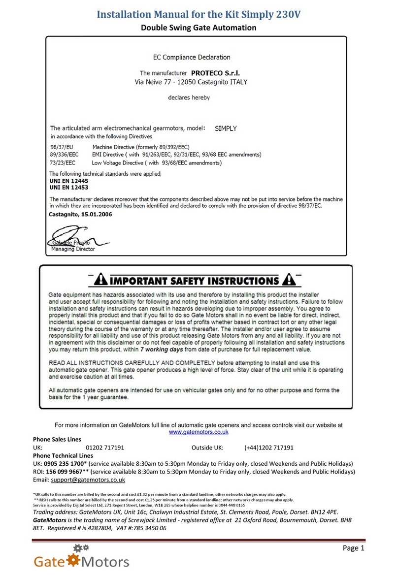
Proteco SIMPLY User manual

Proteco

Proteco SIMPLY User manual

Proteco Advantage User manual

Proteco

Proteco Advantage User manual

Proteco BARRY User manual

Proteco

Proteco BARRY User manual

Proteco MyGate myaster Guide

Proteco

Proteco MyGate myaster Guide

Proteco Mover 4 Guide

Proteco

Proteco Mover 4 Guide

Proteco BALANCE User manual

Proteco

Proteco BALANCE User manual

Proteco MATRIX User manual

Proteco

Proteco MATRIX User manual

Proteco ASTER NEW User manual

Proteco

Proteco ASTER NEW User manual

Proteco Shark Guide

Proteco

Proteco Shark Guide

Proteco leader ta Guide

Proteco

Proteco leader ta Guide

Proteco Advantage Guide

Proteco

Proteco Advantage Guide

Proteco MOVER Guide

Proteco

Proteco MOVER Guide

Proteco Shark New Guide

Proteco

Proteco Shark New Guide

Proteco leader ta Guide

Proteco

Proteco leader ta Guide

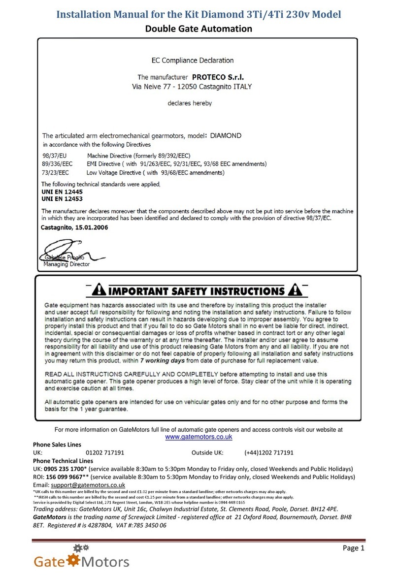
Proteco Diamond 3Ti User manual

Proteco

Proteco Diamond 3Ti User manual

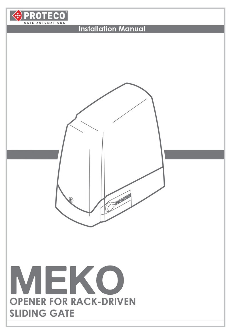
Proteco MEKO User manual

Proteco

Proteco MEKO User manual

Popular Gate Opener manuals by other brands

fadini DARDO 430 instruction manual

fadini

fadini DARDO 430 instruction manual

Casit SCORRY500J manual

Casit

Casit SCORRY500J manual

tau MASTER Maintenance manual

tau

tau MASTER Maintenance manual

Tormatic STS T2E installation instructions

Tormatic

Tormatic STS T2E installation instructions

Dea LIVI 403E Operating instructions and warnings

Dea

Dea LIVI 403E Operating instructions and warnings

Chamberlain MyQ Smart Garage Hub installation guide

Chamberlain

Chamberlain MyQ Smart Garage Hub installation guide

Motorline professional TEC100 installer and user manual

Motorline professional

Motorline professional TEC100 installer and user manual

Superior BT installation manual

Superior

Superior BT installation manual

D.A.C.E DURASWING Installation and owner's manual

D.A.C.E

D.A.C.E DURASWING Installation and owner's manual

IQ Gate Systems IntelliSlide IQ-5000-HD Installation and instruction manual

IQ Gate Systems

IQ Gate Systems IntelliSlide IQ-5000-HD Installation and instruction manual

KEY RAY user manual

KEY

KEY RAY user manual

Elsema INTELLIGENT SLIDER iS1500LV user manual

Elsema

Elsema INTELLIGENT SLIDER iS1500LV user manual

Viking G-5 Installation instructions and safety information

Viking

Viking G-5 Installation instructions and safety information

AGS 105 How to install

AGS

AGS 105 How to install

Beninca DU.35 Operating instructions and spare parts catalogue

Beninca

Beninca DU.35 Operating instructions and spare parts catalogue

CAME OPB001CB installation manual

CAME

CAME OPB001CB installation manual

cedamatic CE.ATM Operating instructions and spare parts catalogue

cedamatic

cedamatic CE.ATM Operating instructions and spare parts catalogue

CAME FROG PLUS Series installation manual

CAME

CAME FROG PLUS Series installation manual

manuals.online logo
manuals.online logoBrands
  • About & Mission
  • Contact us
  • Privacy Policy
  • Terms and Conditions

Copyright 2025 Manuals.Online. All Rights Reserved.