Proteco leader ta Guide

Leader
LEADER TI
LEADER TA
PRODOTTI
PRODUITS
PRODUCTS
ERZEUGNIS
PRODUCTOS
Manuale d’Installazione e d’Uso
Manuel d'Installation et Utilisation
Installation and use manual
Handbuch der Installation und des Gebrauchs
Manual de Uso e Instalación
14_2008
AUTOMAZIONI PER CANCELLI A BATTENTE
AUTOMATISMES POUR PORTAILS A BATTANTS
AUTOMATION FOR SWING GATES
AUTOMATISIERUNG FÜR FLÜGELTORE
AUTOMATISMOS PARA BATIENTES
Proteco S.r.l. Via Neive, 77 - 12050 Castagnito (CN) ITALY

CARATTERISTICHE TECNICHE - CARACTERISTIQUES TECHNIQUES
TECHNICAL FEATURES - TECHNISCHE ANGABEN - CARACTERISTICAS TECNICAS
1 Attuatore - Moteur
2 Centrale elettronica -
3
4
5
6
7
- Operator - Torantriebe - Actuador
Centrale électronique - Electronic control unit - Torsteuerung - Cuadro electrónico
Fotocellule - Photocellules - Photocells - Fotozellen - Fotocélulas Rx
Tx
Antenna -Antenne -Aerial -Antenne -Antena
Ricevitore radio - Récepteur radio - Radio Receiver - Funkempfänger - Receptor radio
Lampeggiatore - Clignotant - Warning light - Blinkleuchte - Luz Intermitente
Selettore a chiave - Contacteur a clé - Key contactor - Schlüsselschalter - Selector de llave
--
SCHEMA FUNZIONALE - SCHÉMA DE FONCTIONNEMENT
OPERATIONAL DIAGRAM - FUNKTIONSPLAN - ESQUEMA FUNCIONAL
A 3 x 1,5+T 2 x 1
B 2 x 1,75+T
E 2 x 0,75 2 x 0,75
G 2 x 0,75 2 x 0,75
F 2 x 0,75
2 x 1,75+T
C 2 x 0,75 2 x 0,75
2 x 0,75
2 x 0,75 2 x 0,75
_
C¹ 4 x 0,75 4 x 0,75
D
4 TA3 TI 4 TI
3 110 TI
5 TI
4 110 TI
3 12 TI
4 12 TI
4 12 TA
5 12 TI
46
3
3
3
3
1
1
2
AA
F
D
230V B
C¹
C¹ C
C
E / G
5
7
230V 12V
Alimentazione - Alimentation - Power supply - Anschluss - Alimentaci n
Assorbimento - Consommation - Absorption - Stromaufnahme - Absorción de línea
Potenza - Puissance moteur - Motor power - Motorleistung - Potencia
Condensatore - Condensateur - Capacitor - Kondensator - Condensador
Protezione termica - Protection thermique - Thermic protection
Thermoschutz - Protecci n térmica
Spinta max - Poussée - Maximum thrust - Drehmoment - Empuje máx
Grado IP - Classe IP - IP level - Schutzart IP - Grado de protección IP
Giri motore - Vitesse moteur - Motordrehzahl - Rotación del motor
Temperatura di funzionamento - Température de service - Working temperature
Temperaturbereich - Temperatura de servicio
Lunghezza max anta - Vantail maximum - Leaf’s maximum length
Max. Flügelgellänge - Longitud máx. hoja
Peso max anta - Poids maximum du vantail - Leaf-s maximum weight
Max. Flügelgewicht - Peso máx. hoja
Corsa max - Course standard - Standard stroke - Laufweg - Carrera máx.
Angolo max di apertura - Angle max d’ouverture - Maximum opening
Max. Öffnungswinkel - Ángulo máx. de abertura
Tempo di apertura 90° - Temps d’ouverture 90°- 90° opening time
Öffnungszeit - Velocidad angular 90°
Ciclo di lavoro - Cycle de travail - Duty cycle - Benutzungshäufigkeit - Ciclo de trabajo
ó
ó
Revolutions speed -
230V ~ 50Hz
1,2 - 1,7 A
280 W
10 µF
2800 N
54
1400 g/m
110° 110° 110°
40 % 80 % 40 %
150° 150°
12V dc
0,7 - 9,5 A
40 W
110V dc
2,5 - 2,6A
300 W
30 µF
1800 N
54
1500 g/m
3000 N
54
1600 g/m
17” 17”
2,00 m 1,75 m
350 Kg 150 Kg 350 Kg
300 mm 300 mm 300 mm
22” 22” 18”15”
27”
2,75 m 2,00 m 2,00 m
300 Kg 100 Kg 300 Kg
400 mm 400 mm 400 mm
3,50 m 2,25 m 2,75 m
250 Kg
500 mm 500 mm
_____
_____
-20° - +55°C -20° - +55°C -20° - +55°C

COMPOSIZIONE - COMPOSITION - COMPOSITION - KOMPOSITION - COMPOSICIÓN
01 n°1 Attuatore / Actionneur / Actuator / Triebwerk / Dispositivo
02 n°1 S1 Staffa / Patte / Bracket / Bügel / Abrazadera
03 n°1 Kit fissaggio / Kit fiçaciones / Fixing kit / Befestigungskit
Equipo de fijación
04 n°1 S3/S4 Staffa / Patte / Bracket / Bügel / Abrazadera
05 n°2 Chiave di sblocco / Clé de deblocage / Release key /
Freigabeschlüssel / Llave de desbloqueo
n°1 Manuale d’Installazione e Uso
Notice d'Installation et Utilisation
Installation and Use Manual
Montierung und Gebrauchshandbuch
Manual de Uso e Instalación.
N°1 Manuale Generalità
Notice Generalités
General Instructions manual
Allgemeines Handbuch
Manual Generalidad
01
02
03
04
05
LEADER TI
01
02
03
04
05
LEADER TA
TABELLA 1 - TABLEAU 1 - TABLE 1 - TABELLE 1 - TABELLA 1
200 mm
/
/
175 mm
/
/
150 mm
A
= 98
B
=202
125 mm
A
=123
B
=177
100 mm 75mm 50mm
LEADER 3 TI
LEADER 4 TI
LEADER 5 TI
LEADER 4 TA
A
=168
B
=132
S1
S1
S1 S1 S1 S2
S2 S2
S1 S1
S1 S1
S1
S1
A
=143
B
=157
A
=148
B
=152
A
= 148
B
=252
A
= 173
B
=227
A
= 198
B
=202
A
=193
B
=207
A
=218
B
=182
A
=213
B
=187
A
=205
B
=195
A
=248
B
=252
A
=243
B
=257
A
=268
B
=232
A
=263
B
=237
S2
A
=255
B
=245
A
=280
B
=220
A
=305
B
=195
DD
S1
S1
S1 S1
52
52
52
52 52
52 52
8282
82 82
82 82
112
112
145 145 145
145
DIMENSIONI - DIMENSIONS - DIMENSIONS - RAUMBEDARF - DIMENSIONES
A 1
A
88
20 20
20
170
190 12V)(
01 7
10 2V)9 (1
A A1
LEADER 3 TI 665 965
LEADER 4 TI 765 1165
LEADER 5 TI 865 1365
20
40
400
858
LEADER 4 TA
LEADER TI

S2
S2 dx
sx
S1 dx
S1 sx
Fig. EFig. A
AA
DDBB
A
DB
Fig. N
Fig. O
Fig. M
S3
PR1
G1
Fig. B
AA
BB
1
2
Fig. D
B B
B
B= Fermi meccanici
Butes mécaniques
Mechanical stops
Mechanischen Sperren
Topes mecanicos
Fig. F Fig. G
Fig. I
S1
PR1
G1
Fig. P
Fresatura
Fraisage
Milling
Fräsung
Fresatura
Asola
Boutonniére
Button Hole
Rohröhe
Asta del tubo
Fig. C
Centrale
Centra el
2
1
Fig. S
Fig. Q
S4
M12
Perno di traino
Fig. H
Min. 30 mm
Fig. L
450 mm
50 mm
Fig. R
Leader 3 TI 345 mm
Leader 4 TI 445 mm
Leader 5 TI 545 mm
55 mm
Leader 3 A= 145 B= 145 Leader 4 A= 195 B= 195 Leader 5 A= 245 B= 245

CRITERI DI SICUREZZA
1Prima d’iniziare qualsiasi operazione d’installazione è assolutamente necessario Cancello fissato sullo spigolo del pilastrino (Fig. B)
leggere tutto il presente manuale. In questo caso il cancello può aprire con un angolo maggiore di 90°. (max 120°)
2Verificare che le prestazioni dell’attuatore acquistato corrispondano alle vostre - Il funzionamento ottimale per un’apertura a 90° si ottiene piazzando le staffe alle
esigenze d’ installazione misure indicate nel riquadro in testa alle fig.Ae B.
3Inoltre verificare che: - Per ottenere che l’anta apra con un angolo superiore è necessario fare in modo che la
- Le cerniere del cancello siano in buono stato e perfettamente ingrassate. misura A sia superiore della misura B.
- Il cancello sia dotato di fermi meccanici in apertura ed in chiusura. La soluzione ottimale si ottiene aumentando la misura A della stessa dimensione di cui si
dovrà diminuire la misura B.
CONSIGLI PER L’INSTALLAZIONE
Collegamenti: ALTEZZA DI FISSAGGIO (Fig. G)
• Vedere “Schema funzionale” e fare riferimento agli schemi della centrale di comando. Determinare l’altezza di fissaggio dell’attuatore in funzione dalla forma del cancello e dalle
• Il cavo elettrico in uscita dall’attuatore non deve essere teso, ma fare un’ampia curva possibilità di fissaggio su di esso.
verso il basso onde evitare il riflusso di acqua all’interno dell’attuatore stesso. (Fig. O) a) Se la struttura del cancello è robusta si può posizionare a qualsiasi altezza senza limitazioni.
• Tutti i collegamenti devono essere effettuati in assenza d’alimentazione. b) Se la struttura è leggera occorre tenere l’attuatore più vicino possibile alla mezzeria del
• Prevedere un dispositivo di sezionamento onnipolare nelle vicinanze dell’impianto cancello(inaltezza).
(i contatti devono essere di almeno 3 mm). Posizione 1 Traversa centrale del cancello
Proteggere sempre l’alimentazione per mezzo di un interruttore automatico da 6A, Posizione 2 Rinforzo del cancello
oppure per mezzo di un interruttore monofase da 16Acompleto di fusibili.
• Le linee d’alimentazione ai motori, alla centrale e le linee di collegamento agli FISSAGGIO STAFFE S1 / S2
accessori devono essere separate onde evitare disturbi che potrebbero generare mal Tassellare o saldare sul pilastroa lato del cancello la staffa S1 oS2, ricordando che le misure
funzionamenti dell’impianto. A eB sono riferite all’asse delle cerniere del cancello e all’asse di rotazione dell’attuatore. Nel
• Qualsiasi apparecchiatura (di comando o sicurezza) eventualmente asservita alla caso di fissaggio a mezzo tasselli ad espansione utilizzare tasselli metallici Ø 13 mm e tenere
centrale deve essere libera da tensione (contatti puliti). presente che il tassello deve essere posizionato a non meno di 30÷35 mm dallo spigolo del
Parti di ricambio: pilastrino per evitare la possibile rottura dello spigolo (Fig. H).
• Utilizzare solamente parti di ricambio originali. Nel caso di pilastrini in muratura utilizzare tasselli chimici o in resina oppure una staffa
• Non eliminare le batterie con i rifiuti urbani ma smaltirle come rifiuti industriali. opportunamente murata.
(Legge n.475/88) - Fare attenzione all’utilizzo della staffa S1 (Fig. E), la quale dispone di due versioni, staffa
Modalità d’installazione: S1 destra e staffa S1 sinistra, da utilizzare con il proprio attuatore: destro o sinistro.
• Per un uso proprio del prodotto e per escludere ogni possibilità di danneggiamenti a - Fissare l’attuatore alla staffa S1 come indicato in “Fig. I” ricordando che il foro filettato
persone, animali o cose, fare riferimento al foglio "Generalità" allegato che fa parte del perno di rotazione PR1 deve essere rivolto verso il basso.
integrante del presente manuale.
• L'impiego di questa apparecchiatura deve rispettare le norme di sicurezza vigenti nel STAFFE S2 (Fig. F)
paese d’installazione oltre alle norme di buona installazione. In alcuni casi indicati nella tabella 1 e per particolari applicazioni è consigliabile usare le
Garanzia: staffe S2. Cadauna staffa è composta da n° 1 piastra quadrata con dimensioni cm
• La garanzia fornita dal costruttore decade in caso di manomissione, incuria, uso 130x130x6, completa di 4 fori da Ø 12, e da n° 1 staffa 112x94x55 mm con 3 fori da Ø12.
improprio, fulmini, sovratensioni o utilizzo da parte di personale non professionalmente Modalità di posa
qualificato. - Tassellare la piastra quadrata al pilastrino con robusti tasselli.
• Fa inoltre decadere qualsiasi diritto alla garanzia: - Saldare la staffa alla piastra come indicato nella fig. F
Il mancato rispetto delle istruzioni riportate sui manuali allegati ai prodotti. Ricordare che le misure A e B sono riferite all’asse delle cerniere del cancello e all’asse di
L'applicazione anche di un solo particolare in modo non conforme alla legislazione rotazione.
vigente o l'utilizzo di parti di ricambio non idonee e/o non espressamente approvate
dalla ditta costruttrice. FISSAGGIO DELLA STAFFA ANTERIORE
• Il costruttore non può considerarsi responsabile per eventuali danni causati da usi Attuatore LEADER TA (versione con tubo alluminio)
impropri ed irragionevoli. Determinare la posizione della staffa S4 nel modo seguente:
- Chiudere l’anta del cancello.
SEQUENZA DI INSTALLAZIONE - Sbloccare l’attuatore.
1Prima di iniziare la posa, effettuare l’analisi dei rischi dell’installazione facendo - Far avanzare il perno anteriore dell’attuatore fino a raggiungere la posizione di
riferimento al foglio “Generalità” che fa parte integrante del presente manuale, finecorsa in apertura (tenere 20 mm di fiato tra il perno e il fine asola del tubo). (Fig. L).
compilare la tabella tecnica e eliminare i rischi rilevati. - Fissare la staffa S4 al perno anteriore dell’attuatore come indicato in “Fig. M”
Nel caso in cui vi siano rischi residui, prevedere l’installazione di sistemi di sicurezza ricordando che la fresatura del perno di traino deve essere posizionata
complementari. longitudinalmente all’asola per evitare mal funzionamenti. (Fig. P)
2Verificare le norme di sicurezza citate nei “Criteri di sicurezza”. - Presentare l’attuatore sull’anta del cancello mantenendolo in bolla e segnare la
3Identificare l’attuatore destro e l’attuatore sinistro. posizione della staffa S4 sul cancello.
4Verificare la conformità di tutti i componenti. - Saldare o imbullonare la staffa S4 al cancello.
5Identificare il punto di ancoraggio sul pilastrino e di conseguenza sul cancello. - Verificare di aver posizionato il perno di trascinamento con i due lati della fresatura
6Verificare la misura “D” paralleli all’asola del tubo in alluminio come indicato in “Fig. Q”.
7Adattare la staffa S1 o S2 secondo la “TABELLA 1”, Attuatore LEADER TI (versione con tubo inox)
8Ancorare il pistone alla staffa S1 o S2. Determinare la posizione della staffa S3 nel modo seguente:
9Sbloccare l’attuatore. - Chiudere l’anta del cancello.
10 Ancorare la staffa S3 / S4 sul cancello.
11 Ancorare la manina del pistone TI alla staffa S3 o il perno di traino del pistone TA alla
staffa S4.
12 Stendere i cavi come da “Schema funzionale”.
13 Collegare la centrale e tutti gli accessori
14 Programmare il ricevitore radio.
15 Eseguire la programmazione dei “TEMPI DI FUNZIONAMENTO”.
In caso di mal funzionamento, fare riferimento al paragrafo “Anomalie e consigli”
delle “Generalità”.
ATTUATORE BLOCCATO FERMI MECCANICI (Fig. D)
Gli attuatori sono forniti in versione bloccata. A questo punto occorre posizionare i fermi meccanici del cancello per effettuare
L’elettroserratura deve essere installata sull’anta che si apre per prima e deve essere rispettivamente il fermo in chiusura ed il fermo in apertura dell’anta.
collegata ai relativi morsetti della centrale. Attuatore LEADER TA (versione con tubo alluminio)
Posizione dell’elettroserratura: (Fig. C) Con anta chiusa la distanza tra il perno di trascinamento e la parte anteriore del pistone
Posizione 1: Scrocco di chiusura nella battuta dovrà essere al massimo di 450 mm per il Leader 4 TA.
(in questo caso è necessario utilizzare il paletto modello RT15 sulla seconda anta). Con anta aperta questa misura dovrà essere minimo di 50 mm. (Fig. L)
Posizione 2: Scrocco di chiusura a pavimento Attuatore LEADER TI (versione con tubo inox)
(in questa posizione l’utilizzo del paletto non è indispensabile). Con anta chiusa lo stelo del pistone dovrà fuoriuscire al massimo di 335 mm per il
Ricordarsi di eliminare la serratura o quanto meno renderla inattiva bloccando lo scrocco in Leader 3 TI , di 435 mm per il Leader 4 TI e di 535 mm per il Leader 5 TI.
posizione aperta ed eliminare tutti i paletti di chiusura. Con anta aperta lo stelo dovrà fuoriuscire minimo di 65 mm. (Fig. R)
ATTUATORE DESTRO O SINISTRO (Fig. D) APERTURA DEL CANCELLO VERSO L’ESTERNO
Gli attuatori sono forniti in versione destra e sinistra. Nel caso il cancello apra verso l’esterno è possibile posizionare l’attuatore all’interno.
Per stabilire se si necessita di un attuatore Destro o Sinistro guardare il cancello dal lato in In questo caso la quota A (distanza tra asse delle cerniere ed asse di rotazione
cui è installato l’attuatore, se le cerniere sono sulla destra l’attuatore è destro, se sono sulla dell’attuatore) deve essere misurata verso il centro del cancello ed occorre modificare la
sinistra l’attuatore è sinistro. staffa S2 per renderla adatta alla nuova posizione di fissaggio. (Fig. N)
Per evitare di ridurre la larghezza del passaggio l’attuatore può essere posizionato nella
DETERMINAZIONE QUOTE DI FISSAGGIO parte alta del cancello ad un’altezza non inferiore ai 2 mt.
Cancello fissato al centro del piastrino (Fig. A) La posizione della staffa anteriore si trova con il metodo sopra specificato, ma con l’anta del
In questo caso l’angolo massimo di apertura del cancello è di 90°.cancello aperta. Considerata la potenza sviluppata dal motore, verificare con attenzione la
- Il funzionamento ottimale si ottiene piazzando le staffe alle misure indicate nel robustezza dei fassaggi.
riquadro in testa alle fig. Ae B.
Nell’ ipotesi che ciò sia di difficile attuazione procedere come segue: SBLOCCO DELL’ATTUATORE
- Misurare la quota D (distanza tra l’asse delle cerniere e lo spigolo del pilastrino). - Inserire e ruotare di 90° in senso orario l'apposita chiave fornita in dotazione. (Fig. S)
- Consultare la Tabella 1, seguire la riga corrispondente al modello di attuatore - Tirare la leva di sblocco verso l'esterno fino ad ottenere lo sblocco dell'attuatore, quindi
acquistato fino ad incrociare la colonna relativa alla quota D.ruotare la chiave di altri 90° per bloccare la leva.
- Nel riquadro individuato potrete trovare le indicazioni necessarie a stabilire il miglior - Aquesto punto è possibile aprire e chiudere manualmente il cancello.
utilizzo della staffa S1 (Fig. E), o in alternativa della staffa S2 in opzione. (Fig. F) - Fare l’operazione inversa per riagganciare l’attuatore.
Queste quote sono calcolate per ottenere una velocità tangenziale media che non superi i Non è necessario che il cancello sia in una posizione specifica in quanto al prossimo
12 mt/min. comando si ripristineranno tutti i valori.
- Sbloccare il motore.
- Far ruotare completamente lo stelo inox fino al raggiungimento di battuta (max corsa).
- Far rientrare lo stelo inox di circa 2 cm.
- Posizionare la staffa S3 nella manina con perno PR1 e relativo grano di tenita “Fig.
L” (N.B.: parte inferiore)
- Appoggiare la staffa S3 sull’anta mantenendo l’attuatore in posizione orizzontale
usando una livella, fissare con vite o saldare.
N.B.: Prima di saldare definitivamente le staffe provare ad aprire manualmente
l’anta verificando che riesca ad eseguire manovra completa soddisfacente.
ITALIANO

CRITÈRE DE SÉCURITÉ
Avant de commencer une quelconque opération d'installation il est absolument
indispensable de lire entièrement ce manuel.
2Vérifier que le kit est bien adapté en fonction des caractéristiques du portail.
3Vérifier que :
• Les charnières du portail soient en bon état.
• Qu'il y ait des butées latérales (obligatoires).
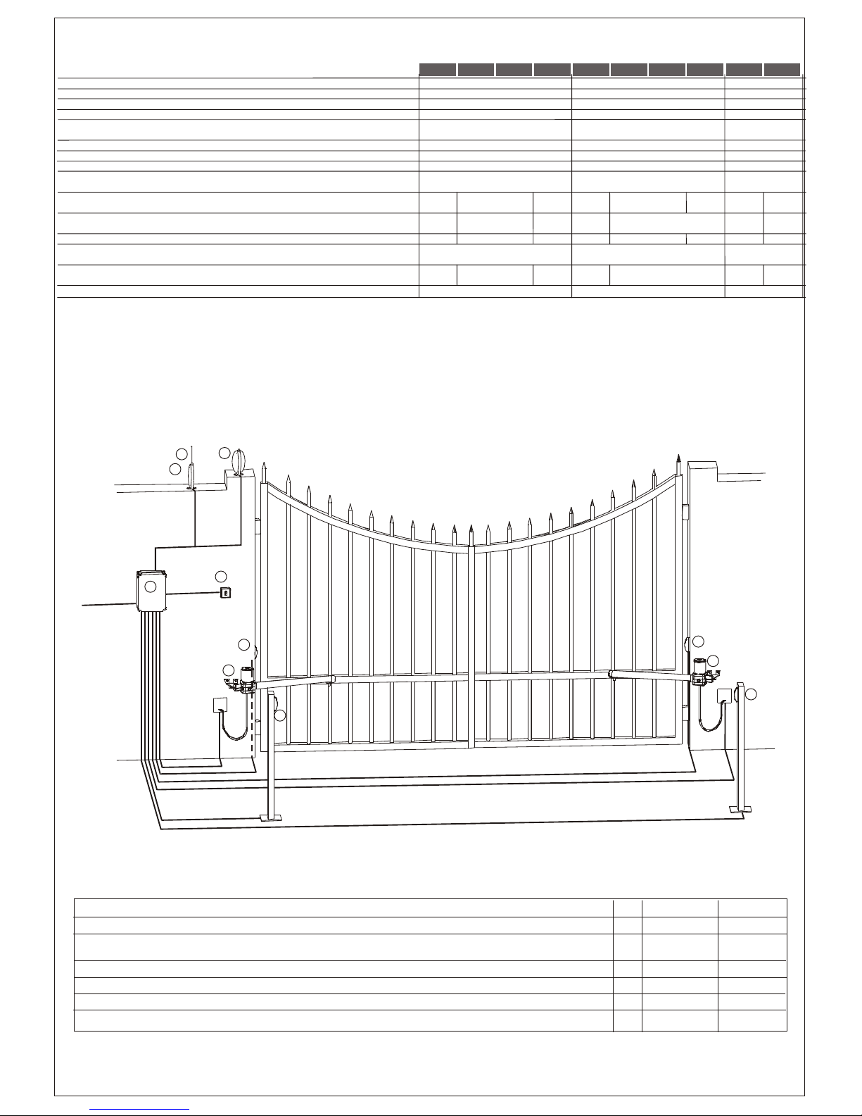
CONSIGNE POUR L'INSTALLATION
Raccordements :
• Utilisez le “Schéma de fonctionnement” et le schéma delà centrale électronique.
• Le câble électrique en sortie du moteur ne doit pas être tendu, mais faire une courbe
vers le bas pour empêcher que l'eau suinte a l'intérieur du moteur. (Fig. O)
• Tous les branchements doivent être effectués en absence d'alimentation électrique.
Prévoir un dispositif de sécurité, tel un différentiel ou disjoncteur (6Amp) sur la ligne
de l'appareil .
• Les lignes d'alimentations que ce soit aux moteurs, à la centrale ainsi que les lignes
d'alimentation des accessoires doivent être séparés pour éviter toutes interférences
qui pourraient causer des fonctionnements aléatoires de l'installation.
Pièces de rechange:
• Utiliser seulement pièces de rechanges d'origines.
• Ne détruisez pas les batteries comme des déchets qui sont habituellement enlevés
par le ramassage municipale, mais traitez-les comme des déchets industriels.
( lois n. 475/88)
Modalité d'installation :
• Pour une utilisation appropriée du produit et pour exclure toute possibilité de
dommages aux personnes, animaux ou véhicules, faire référence à la feuille
"Généralités" en annexe qui fait partie intégrante de ce manuel.
• L'emploi de ce dispositif doit respecter les normes de sécurité en vigueur dans le pays
d'installation ainsi que les normes de bonne installation.
Garantie :
• La garantie fournie par le constructeur est annulée en cas d'altération, de manque
d'entretien, d'utilisation impropre, de foudre, de surtension ou d'utilisation de la part de
personnel non qualifié professionnellement.
• Tout droit à la garantie s'annulera également en cas de:
Non respect des instructions reportées sur les manuels fournis avec les produits.
L'application même d'une seule pièce suivant une modalité non conforme à la
législation en vigueur ou l'utilisation de pièces de rechange non conformes et/ou non
expressément approuvées par le fabricant.
• Le constructeur ne pourra être tenu responsable des dommages éventuels
occasionnés suite à une utilisation impropre et inappropriée.
SEQUENCE D'INSTALLATION
1Avant de commencer quelconque opération d'installation est absolument
indispensable de lire tout cet manuel.
2Le “Critère de sécurité”
3Identifier le moteur droit et gauche.
4Vérifier la composition.
5Déterminer la position pour la fixation des les pattes.
6Vérifier la côte “D”
7Adapter le patte S1 ou S2 en correspondance du Tableau 1.
8Positionner les moteurs sur les pattes S1 or S2.
9Déverrouillage du moteur.
10 Fixer le patte S3 / S4 sur le portail.
11 Fixer la patte S3 à l'embout de fixation du moteur TI ou la patte S4 à la découpe du
moteur TA.
12 Positionner le fil comme da “Schéma de fonctionnement ”
13 Brancher la centrale à toutes les accessoires.
14 Programmez les télécommandes.
15 Programmez le “Temps de fonctionnement”.
16 Au cas de dysfonctionnement regarder la rubrique “Anomalies et Conseils”.
Au cas ou ce tableau ne répondrait pas a vos questions et ne résoudrait pas votre
disfonctionnement appeler notre service technique.
ACTIONNEUR BLOQUE
Les moteurs peuvent être fournis en version autobloquants.
L'électro-serrure doit être installée sur le vantail qui s' ouvre en premier et doit être reliée à
la barrette de raccordement de la centrale.
Position de la serrure électrique. (Fig. C)
Position 1: Serrure dans la battue.
(dans ce cas il est nécessaire utiliser le verrou model RT15 sur le deuxième vantail).
Position 2: Serrure au sol.
(dans ce cas n'est pas indispensable utiliser le verrou).
Il faut se rappeler de neutraliser la serrure d'origine ou au moins en la bloquant en position
ouverte et éliminer tous les verrous de fermeture.
ACTIONNEUR DROITE OU GAUCHE (Fig. D)
Les moteurs sont fournis en version droite ou gauche.
On établit que le vérin est Droit ou Gauche en regardant le portail du côté intérieur; si les
charnières sont à droite l'actionneur est droite, si les charnières sont à gauche l'actionneur
est gauche.
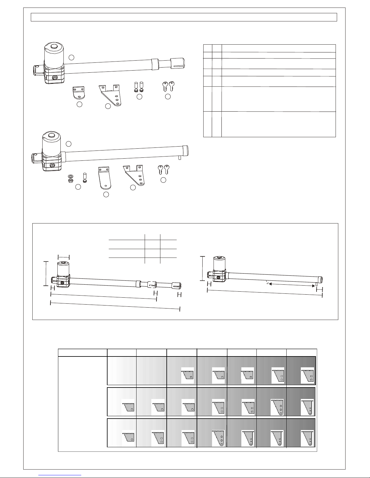
DETERMINATION DES COTES DE FIXATION
Portail fixé au centre du pilier (Fig. A)
Dans ce cas l'angle maximum d'ouverture du portail est de 90°.
- Pour obtenir un fonctionnement optimal il faut placer les pattes selon les mesures
indiquées dans l'encadré sur les fig.Aet B.
Dans l'hypothèse ou cela n'est pas possible procédez comme suit:
- Mesures la cote “D” (distance entre l'axe des charnières et le bord du pilier).
- Consultez le Tableau 1 et suivez la ligne où se trouve le modèle du système que vous
avez acheté jusqu'à trouve la colonne qui correspond à la cote D.
- Dans ce tableau vous avez les indications nécessaires pour établir le meilleur emploi
de la patte S1 (Fig. E) ou bien de la patte S2 en option (Fig. F).
Ces cotes on été calculées pour obtenir une vitesse tangentielle moyenne qui ne dépasse
pas les 12 m/min.
1Vous aurez la solution optimal en augmentant la mesure A de la même dimension que
vous diminuerez la mesure B.
HAUTEUR DE FIXATION
Déterminer la hauteur de fixation de moteur en fonction de la forme du portail et des
possibilités de fixation sur celle-ci. (Fig. G)
a) Si la structure du portail est robuste vous pouvez placer le moteur à n’importe quelle
hauteur.
b) Si la structure du portail est fragile il faut placer le moteur le plus prés possible de la mi-
hauteur du portail.
Position 1 Traverse centrale du portail
Position 2 Renfort du portail.
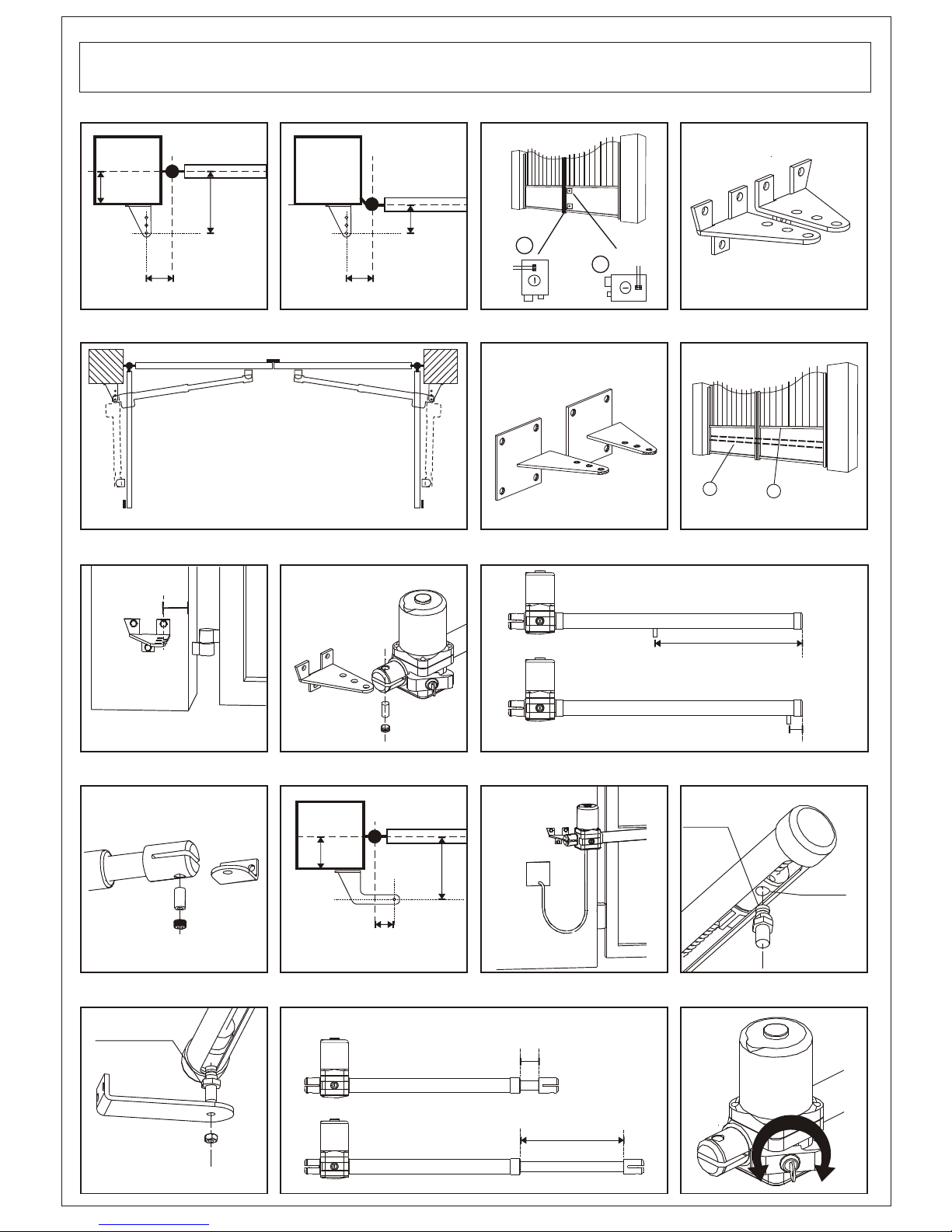
FIXATION DES PATTES
Cheviller ou souder sur le poteau à côté du portail la patte S1 ou S2 comme spécifié, sans
oublier que les cotesAet B se réfèrent à l'axe des charnières du portail et à l'axe de rotation
du moteur.
En cas de fixation avec chevilles utiliser des chevilles de Ø13 mm. et ne pas oublier que la
cheville doit être positionnée à une distance non inférieure à 30 ÷ 35 mm. de l'arête du
poteau afin d'éviter la rupture possible de l'angle. (Fig. H).
Dans le cas de pilier creux utiliser des chevilles chimiques ou en résines.
- Faire attention à l’utilisation de la patte S1 (Fig. E) la quelle dispose de deux versions,
patte S1 droite et patte S1 gauche, à utiliser avec le moteur droit ou bien gauche.
- Fixer le moteur à la patte S1 comme en “Fig. I” en ce rappelant que le trou fileté du pivot
de rotation PR1 doit être vers le bas.
PATTE S2 (Fig. F)
Dans certains cas indiqués dans le Tableau 1 et pour des application particulières il est
conseillé d’utiliser la patte S2.
Toutes le patte sont composées par 1 plaque carré (dimensions 130x130x6 mm) de 4 trous
Ø12 mm et d’une patte 112x94x55 mm avec 3 trous Ø12 mm.
Mise en place
- Fixer la plaque carré au pilier avec des chevilles de qualités.
- Souder la bride à la plaque comme indiqué dans la Fig. F.
Souvenez-vous que les mesures Aet Bse réfèrent à l’axe des charnières du portail à l’axe
de rotation du moteur.
FIXATION DE LA PATTE ANTÉRIEURE
Vérin LEADER TA (version avec tube alu)
Déterminer la position de la patte S4 de la façon suivante:
- Fermer le portail.
- Débloquer le moteur.
- Avancer le pivot antérieur du moteur justqu’à la position de fin de course en ouverture.
Reculer 20 mm pour éviter des problèmes en fermeture est mieux laisser 20 mm
d’espace entre le pivot et le bouchon antérieure de moteur. (Fig. L)
- Fixer la patte S4 au pivot antérieure du moteur comme indiqué en “Fig. M” en se
rappelant que le fraisage du pivot de traînement doit être positionnée longitudinalement
à la lumière d’entraînement pour éviter des fonctionnement défectueux. (Fig. P)
- Présenter le moteyr sur le vantail du portail en le maintenant à niveau et marquer la
position de la patte S4 sur le portail.
- Souder ou boulonner la patte S4 au portail.
- Vérifier d’avoir positionné le goujon d’entraînement avec les deux côtés de la lumière
parallèles au tube en aluminium comme indiqué dans la “fig. Q”.
Vérin LEADER TI (version avec tube inox)
Déterminer la position de la patte S3 de la façon suivante:
- Fermer le portail.
-
BUTES MÉCANIQUES (Fig D)
Il faut alors positionner les butées mécaniques (obligatoires) pour effectuer
respectivement l'arrêt en fermeture et l'arrêt en ouverture du portail.
Vérin LEADER TA (version avec tube alu)
Quand le portail est fermé la distance entre l’axe du pivot de traînement et la partie
anterieure du moteur doit etre maximum 450 mm pour le Leader 4 TA.
Quand le portail est ouverte cette mesure doit etre minimum 50 mm. (Fig. L)
Vérin LEADER TI (version avec tube inox) (Fig. R)
Quand le portail est fermé, le verin doit sortir au maximum de 335 mm pour le Leader 3
TI , de 435 mm pour le Leader 4 TI et de 535 mm pour le Leader 5 TI.
Quand le portail est ouverte le verin doit sortir au minimum de 65 mm.
PORTAIL A OUVERTURE VERS L’EXTERIEUR
En cas le portail s’ouvre vers l’exterieur il est possible de positionner le moteur à l’intérieur.
Pour ce cas la cote A (distance entre l’axe des charnières et l’axe de rotation du moteur)
doit être mesure vers le centre du portail et il faut modifier la patte S2 pour l’adapter à la
nouvelle position de fixation. (Fig. N)
Pour éviter de réduire la largeur du passage les moteurs peuvent être positionnés en haut
du portail à une hauteur qui permettra le passage du véhicule.
La position de la patte antérieure se trouve avec la méthode ci dessous spécifié, mais avec
portail ouvert.
Selon la puissance développée par le moteur toutes les fixations doivent être robustes.
DEBLOCAGE DU MOTEUR
- Introduire et tourner de 90° dans le sens des aiguilles d'une montre la clé en dotation. (Fig. S)
- Tirer le levier de déblocage vers l'extérieur jusqu'à obtenir le déblocage du moteur,
puis tourner à nouveau la clé de 90° pour bloquer le levier.
- Il est alors possible d'ouvrir et fermer le portail manuellement.
Portail fixé au bord du pilier (Fig. B) - Faire l’opération inverse pour raccrocher le moteur.
Dans ce cas le portail peut s’ouvrir avec un angle de plus de 90°.(max 120°) Il n’est pas nécessaire que le portail soint dans une position particulière parce que lors du
- Pour obtenir un fonctionnement optimal avec une ouverture à 90° il faut placer les prochain cycle toutes les valeurs serons remises à la l’état initial.
pattes selon les mesures indiquées dans l’encadré sur les fig.Aet B.
- Si vous voulez obtenir un angle supérieur il est nécessaire que la mesure A soit
supérieure à la mesure B.
Déverrouillez le vérin
- Tournez complètement le tube inox jusqu’à la butée (course max)
- Faites renter le tube inox à peu prés pour 2cm
- Positionnez la patte S3 dans le vérin avec la cheville PR1 et son grain de fixation.
(Fig. L ) (N.B. section inferieure)
- Appuyez la patte S3 sur le vantail gardant le vérin en position horizontale à l’aide
d’une livelle et fixez avec une vis ou soudez-le.
N.B. Vérifiez l’ouverture manuelle du vantail avant de fixer définitivement les pattes
et controlez que le vantail accomplie une manoevre satisfaisante.
FRANÇAIS

SAFETY CRITERIA HEIGHT OF INSTALLATION
1
INSTALLATION ADVICE
Connections:
•
BRACKETS S2 (Fig. F)
INSTALLATION INSTRUCTION SEQUENCE
1
LEADER TI operators (version with inox tube).
-
MECHANICAL STOPS (Fig. D)
BLOCKED ACTUATOR
EXTERNAL OPENING GATE
RIGHT OR LEFT ACTUATORS (Fig. D)
(Fig. A)
.
(Fig. B)
Attention: before beginning the installation it is absolutely necessary to read all this Calculate the height of the installation of the actuator according to the gate's shape and to
manual. the possibilities of fastening (Fig. G)
2Verify that the technical features of the actuator fit your installation needs. a) If the gate has a big structure you can put the actuator at any highness with no limits.
3Moreover verify that: b) If the structure is light it is necessary to keep the actuator the nearest possible to the
• The gate hinges are in good conditions and perfectly lubricated. middle of the gate (in height).
• The gate has mechanical stops in opening and closing Position 1 Central beam of the gate
Position 2 Stiffen of the gate
FIXING OF BRACKETS S1/S2
See the “Functional Scheme” and refer to the control board scheme. Bolt or weld the bracket S1 or S2 on the gate's side pillar, keeping in mind that the measures
• The electric cable which exits from the actuator must not be tight, but it has to do an A and Brefer to the gate hinges axis and to the actuator's rotation axis.
ample curve towards the bottom in order to avoid water reflux inside the actuator. (Fig.O) In case of fastening by expansion bolts, use Ø 13 mm metal bolts and place the bolt at no
• All connections must be done when the device has no power supply. less than 30÷35 mm from the pillar's corner, to avoid breaking of corner. (Fig. H)
• You may need a omni polar breaking device (the cables must measure at least 3 mm) In case of masonry pillars, use chemical or resin bolts or stone the bracket.
Always protect the power supply using a 6A automatic switch, or a 16A single-phase - Be careful in using bracket S1 (Fig. E) which is in two versions: bracket S1 right end
switch with fuses. bracket S1 left, they should be used with their actuator; left or right.
• The power supply lines to the motors, to the control unit and to the accessories must - Fasten the actuator to bracket S1 as indicated in “Fig. I”, please pay attention that the
be separated to avoid interferences which could generate problems to the system. threaded hole of the rotating pivot PR1 must be turned down.
• Any equipment (either of control or safety) in case connected to the control unit must
be tension free.
Spare parts: In some cases, as indicated in table 1, and for particular installations it is better to use
• Use original spare parts exclusively. bracket S2.
• Get ridof batteries putting them with industrial rubbish and not with domestic rubbish . Each bracket is made up of 1 a squared plate, dimensions 130x130x6 mm, with 4 holes of
(Law n. 475/88). Ø12 mm and 1 bracket 112x94x55 mm with 3 holes of Ø 12 mm.
Installation: How to fix brackets S2:
• In order to correctly use the product and to exclude the possibility of injury or damage, - Screw theplate tothe pillarusing strongbolts.
refer to the "General instructions" page, which is a part of this manual. - Weld the bracket to the plate as indicated in Fig. F
• The use of this equipment must observe the safety standards in force in the country Remember that the measures A and Brefer to the gate hinges axis and the operator's
where it is installed, as well as the standards governing proper installation. rotation axis.
Warranty:
• The warranty given by the manufacturer becomes invalid in cases of: tampering, FIXING OF FRONT BRACKET
carelessness, improper use, lightening damage, power surges or use by unqualified LEADER TAoperators (version with alum. tube).
personnel. Determine the position of bracket S4 as follows:
• The warranty will also become invalid in the following cases: - Close the gate's wing.
If the instructions given in the manuals supplied with the product are not respected. - Release the actuator.
The application of a part in a manner different from current legislation or the use of - Move forward the front pivot of the actuator until it reaches the position of limit switch in
spare parts which are unsuitable and/or not approved by manufacturer. opening .
• The manufacturer cannot be considered responsible for damages due to improper or Leave 20mm of space between the pivot and the actuator end (Fig. L)
unreasonable use. - Fasten bracket S4 to the front pivot of the actuator as indicated in “Fig. M” keeping in
mind that the threaded hole of the rotating pivot must be turned down and that the
dragging pivot milling must be placed longitudinally to the hole (Fig. P)
Before starting the installation, analyse the risks referring to the chapter “General - Put the actuator on the gate's wing keeping it levelled and mark the position of bracket
instructions”, which is part of this manual, fill in the technical table and eliminate the S4 on the gate.
risks. In case there are still some risks, use security systems during installation. - Weld or bolt bracket S4 to the gate.
2Verify the security laws written in the chapter “Security Criteria” in “General - Control that the drag pin has been positioned with the two sides of the milling in parallel
instructions”. position to the button hole of the alum. tube as indicated in the “Fig. Q”.
3Identify the right actuator and left actuator.
4Control all the components. Determine the position of bracket S3 as follows:
5Identify the fixing point on the pillar and on the gate. - Close the gate's wing.
6Verify measure “D”
7Adapt the bracket S1 o S2 according to “Table1”.
8Fix the actuator to the bracket S1 o S2.
9Release the actuator
10 Fix the brackets S3 o S4 to the gate.
11 Fix the final part of the actuator TI (piece n. 35 in the list of parts) to the bracket S3 or
the driving pivot of the actuator TAto the bracket S4.
12 Stretch the cables as in the “Functional scheme”.
13 Connect the control unit and all accessories.
14 Program the radio receiver.
15 Program the “WORKING TIMES”
In case of anomalies, see the chapter “Anomalies and Suggestions” in “General At this point you need to position the mechanical stops: first the wing's stop in closing and
instructions”then in opening phase.
If you do not find any solution call the nearest Assistance Centre. LEADER TA operators (version with alum. tube).
When the gate is closed the distance between the pivot of dragging and the front part
of the actuator should be at the most of 450 mm for Leader 4 TA.
The actuators are blocked. The electric lock must be installed on the wing that opens first When the gate is open this measure should be at least of 50 mm (Fig. L)
and must be connected with the terminals of the control unit. LEADER TI operators (version with inox tube).
Position of the electric lock: (Fig. C). When the gate is closed the piston's rod may come out of 335 mm for Leader 3 TI, of
Position 1: Lock between the wings 435 mm for Leader 4 TI and of 535 mm for Leader 5 TI at the most.
(in this case it is necessary to use the bolt RT15 on the second wing). When the gate is open, the rod must be out of at least 65mm. (Fig. R)
Position 2: Lock on the floor (in this case the use of the bolt is not essential).
Remember to remove the lock of the gate (or at least leave the lock in open position) and
take away all the bolts. In case of external opening gate is possible to place the actuator on the internal side.
In this case the measure A (distance between the axe of the hinges and the rotation axe of
the actuator) has to be measured towards the centre of the gate, and it is necessary to
The actuators are supplied in Right or Left version. modify the bracket S2 to adapt it to the new fixing position. (Fig. N)
Look the gate from the side where the actuators are installed, if the hinges are on the In order not to reduce the length of the passage, the actuator can be positioned in the
right the actuator is right, if they are on the left the actuator is left. superior part of the gate, at a height not inferior to 2 m.
You can find the position of the front bracket with the method indicated above, but with the
HOW TO DETERMINE FIXING MEASURES wing of the gate open.
Gate fixed in the middle of the pillar Due to the motor's power, all fastenings must be very strong
In this case the maximum opening angle of the gate is 90°.
- The best thing to do is to put the fixing brackets at the measures indicated in the table HOW TO RELEASE THE OPERATOR
above pictureAand B . - Insert the key (supplied in the kit) and rotate it clockwise of 90°. (Fig. S)
If this is difficult to realise, do as follows: - Pull the release lever towards the outside until the actuator is released, then rotate
- Measure the distance D (distance between the hinges' axis and the pillar's edge) again the key of 90° to lock the lever.
- Look in table 1 and find the line of the distance D, then follow it until you cross the line - At this point the gate may be opened or closed manually.
of the model of your operator . - Do the inverse operation to clasp the actuator (turn in opposite direction the provided key)
- In the same table you can see if it is better to use bracket S1 (Fig. E) or alternatively It is not necessary that the gate is in a specific position because the next start impulse will
bracket S2 (Fig. F). restore all the previous values.
These quotes are calculated in order to obtain an average tangential speed that does not
exceed 12 m/minute
Gate fixed on the edge pillar
In this case the gate can open with an angle superior to 90° (max. 120°)
- The best thing to do is to put the fixing brackets at the measures indicated in the
table above picture A and B.
- To make the wing open with a bigger angle, measure A must be superior to
measure B.
The best solution can be obtained increasing measure A of the same dimension of
which measure B must be diminished.
Release the gearmotor.
- Completely rotate the ram up to maximum opening.
- Retract the stainless tube approximately for 2cm.
- Place the S3 bracket into the ram with the PR1 pin and fixing (pict. L)
(NB: lower part)
- Lean the S3 bracket on the leaf keeping the ram perfectly horizontal (you may
better use a spirit-level) and fix the bracket with a screw or weld it.
NB: Check the manual opening of the leaf before definitively fixing the brackets and
make sure that the leaf opens completely.
ENGLISH

SICHERHEITSVORSCHRIFTEN AN DER PFEILERKANTE BEFESTIGTES TOR (Bild. B)
Lesen Sie bitte sorgfältig diese Gebrauchsanweisungen vor dem Anfang jeder In diesem Fall liegt der maximale Öffnungswinkel des Tores über 90° (max. 120°)
Montierung. - Die optimale Funktion für eine Öffnung von 90° erhält man, indem man die Bügel auf
2Überprüfen Sie dass das gekaufte Gerät Ihre Installationsansprüche befriedigt . den Maßen positioniert, die über derAbb.Aund B angegeben sind.
3Außerdem wäre es nötig dass: - Damit sich der Flügel in einem weiteren Winkel öffnet, muss das Maß A größer als
• Die Torscharniere in guten Verhältnissen und gut eingeschmiert sind. das Maß B sein.
• Das Tor mit mechanischen Sperren bei Verschluss und Öffnung ausgerüstet ist Die optimale Lösung erhält man, mit der Vergrößerung des Maßes A , sowie das Maß B
lerringert wird.
HINWEISE ZUR INSTALLATION
BEFESTIGUNGSHÖHE (Bild. G)
Mit Bezug auf die Steuerungsanleitungen, folgen Sie den geschriebenen Anschlüssen. Befestigungshöhe des Kolbens unter Berücksichtigung der Torform und
• Der vomAntriebe herausgehende Kabel muss nicht gespannt sein, sonst ungespannt Befestigungsmöglichkeiten auf diesem bestimmen.
und mit einer breiten Kurve, damit der Rückfluss vom Wasser verhindert wird. (Fig. O) a) Wenn die Torstruktur robust ist, kann man ohne Einschränkungen auf beliebiger
• Die obengenannten Vorgängen müssen unbedingt mangels von Stromversorgung Höhe positionieren.
durchgeführt werden. b) Bei einer leichten Struktur muss man das Stellglied so nah wie möglich an der
• Es wird empfohlen, die Stromleitung entweder mit einem Schaltautomat zu 6A oder Mittellinie des Tors (auf die Höhe bezogen) halten.
mit einem einphasigen Schalter zu 16Akomplett mit Sicherungen zu schützen. Stellung 1 Mittlere Traverse des Tors
• Die Speisungswege der Antriebe, der Steuerung und die Verbindungen mit den Stellung 2 Torverstärkung
Zubehören müssen immer getrennt sein, um Störungen zu vermeiden, die einen
Misslauf in derAnlage bewirken könnten. BEFESTIGUNG DER BÜGEL
• Jede Einrichtung (Steuerung oder Sicherheitsvorrichtung), die zur Steuerung Bügel S1 oder S2 spezifiziert, an den seitlichen Torpfeiler dübeln oder schweißen, dabei
verbunden ist, muss spannungsfrei sein. bedenken, dass die Maße A und Bsich auf die Torscharnierachse und auf die
Ersatzteile: Rotationsachse des Triebwerks beziehen.
• Nur originale Ersatzteile verwenden. Im Falle einer Befestigung durch Expansionsdübel, sollten Ø13 mm Metalldübel
• WICHTIG: die Batterien nicht als Abfall wegwerfen, sondern wie industriellen Abfall verwendet werden, wobei beachtet werden muss, dass der Dübel nicht weniger als 30 ÷
sortieren. (Gesetz 475/88). 35 mm. von der Pfeilerkante entfernt ist, um eine mögliche Beschädigung der Kante zu
Installation: vermeiden (Bild. H).
• Für einen richtigen Einsatz des Produktes und um jede Möglichkeit von Schäden an Falls die Pfeiler sich in der Mauer befinden, chemische Dübel oder Dübel aus Harz
Personen, Tieren oder Sachen auszuschließen, beachten Sie das beiliegende Blatt verwenden oder einen entsprechend eingemauerten Bügel.
“Allgemeines", das als wesentlicher Bestandteil des vorliegenden Handbuchs - Die Anwendung des Bügels S1 (Fig. E) beachten; dieser Bügel ist in der rechten und
anzusehen ist. linken Ausführungen verfügbar, die mit Ihrem rechten oder linken Antrieb benutzbar
• Der Einsatz derAusrüstung muss den geltenden Sicherheitsvorschriften des Landes, sind.
in dem sie installiert wird, sowie den Vorschriften einer ordnungsgemäßen - Den Antrieb an den Bügel S1 befestigen wie im “Bild I” bezeichnet und merken dass
Installation entsprechen. das geschnittene Loch über den Drehzapfen PR1 hinunter gedreht werden muss
Garantie:
• Die vom Hersteller gewährte Garantie entfällt im Falle von unerlaubten Eingriffen in
die Anlage, Nachlässigkeit, Missbrauch, Blitzschlägen, Überspannungen oder bei In einigen in Tabelle 1 angegebenen Fällen und bei besonderen Anwendungen sollte der
Bedienung von unzureichend qualifizierten Personen. Bügel S2 benutzt werden. Jeder Bügel besteht aus Nr. 1 viereckiger Platte mit den
• Auch in folgenden Fällen entfällt jeglicher Garantieanspruch: Nichtbeachtung der Abmessungen 130x130x6 mm, komplett mit 4 Löchern zu Ø 12 mm, und Nr. 1 Bügel
Anleitungen des dem Produkt beiliegenden Handbuchs. zu112x94x55 mm mit 3 Löchern zu Ø12 mm.
Anwendung auch nur eines einzigen Elementes, das nicht den geltenden Aufstellung: Die viereckige Platte mit starken Dübeln am Pfeiler verdübeln.
gesetzlichen Vorschriften entspricht - Den Bügel so an der Platte verschweißen, wie in Abb. F dargestellt.
Verwendung von ungeeigneten Ersatzteilen und/oder von solchen, die nicht - Daran denken, dass sich die Maße A und B auf die Scharnierachse des Tors und auf
ausdrücklich von der Firma genehmigt wurden. die Drehachse beziehen.
• Der Hersteller übernimmt keine Verantwortung für eventuelle Schäden, die auf FIXIERUNG DES VORDERBÜGELS
einen unsachgemäßen und unvernünftigen Einsatz zurückzuführen sind. Antrieb Leader TA (Ausführung mit Rohr aus Aluminium)
Folgendermaßen Position von Bügel S4 bestimmen:
INSTALLATIONSFOLGE
Vor dem Einsatzanfang, lesen Sie sorgfältig das Blatt „Allgemeines“ das als - Torflügel schließen.
wesentlicher Bestanteil dieses Handbuches anzusehen ist und unternehmen Sie - DenAntrieb freigeben.
bitteeinegenaueRisikoanalyse. - Den Vorderzapfen des Antriebs versetzen bis zum Erreichen der
2Die Sicherheitsvorschriften überprüfen. Endanschlagstellung in Öffnung: 20 mm Raum zwischen dem Stift und dem Ende
3Den rechten und linkenAntrieb unterscheiden. des Kolbens lassen (Bild. L).
4Jeden Bestandteil überprüfen. - Den Bügel S4 auf den Vorderstift des Antriebs befestigen wie im Bild M bezeichnet
5Die Verankerungspunkte auf der Säule und auf dem Tor feststellen. merkend dass die Fräsung des Ziehzapfens der Länge nach der Öse positioniert
6Das Maß D überprüfen. sein muss, um Problemen in derArbeitsweise derAnlage zu vermeiden. (Fig. P)
7Den Bügel S1 oder S2 nach der Tabelle 1 anpassen. - Der Kolben auf Torflügel gut ausrichten, Bügelstellung S4 markieren.
8DenAntrieb auf den Bügel S1 oder S2 verankern. - Den Bügel S4 anTor schweißen oder verschrauben.
9DenAntrieb entblocken. - Überprüfen dass der Schleppbolzen richtig gestellt wurde wie gezeichnet im Bild Q
10 Den Bügel S3/S4 auf das Tor verankern. Leader TI kolben (Ausführung aus Edelstahl)
11 Den Endverschluss vom Antrieb TI am Bügel S3 oder den Treibstift vom Antrieb TA Folgendermaßen die Stellung des Bügels S3 bestimmen:
am Bügel S4 befestigen. - Torflügel schließen.
12 Die Kabel wie in dem “Funktionsblatt“ anspannen.
13 Alle Zubehöre und die Steuerung überprüfen.
14 Den Empfänger programmieren
15 Die „Betriebszeiten“ programmieren
Im Fall eines Misslaufs ist es notwendig die Tabelle “Abweichungen und Beratungen”
sorgfältig zu lesen.
Wenn Sie keine Lösung finden können wenden Sie sich bitte an Ihren Lieferant.
BLOCKIERTER ANTRIEB
DieAntriebe werden in blockierterAusführung geliefert.
Der Elektroschloss muss an den ersten öffnenden Flügel montiert werden, und an das
Klemmbrett der Steuerung angeschlossen sein. MECHANISCHEN SPERREN (Fig. D)
Stellung des Elektroschlosses: (Fig. C) Jetzt müssen die mechanischen Sperren positioniert werden, um den Stillstand beim
Stellung 1: Verriegelung zwischen den Toren. Öffnen und beim Schließen des Flügels zu erlauben.
(in diesem Fall ist es notwendig den Pflock RT15 auf den zweiten Flügel zu benutzen). Antrieb Leader TA (Ausführung mit Rohr aus Edelstahl)
Stellung 2: Verriegelung auf dem Boden. (in diesem Fall ist der Pflock nicht Mit geschlossenem Tor muss die Entfernung zwischen dem Schleppzapfen und der
unerlässlich). Innerseite vom Kolben max. 450 mm für den Leader 4 TI sein.
Mit geöffnetem Tor muss dieses Maß mindest. 50 mm sein. (Bild H)
RECHTER UND LINKER ANTRIEB (Bild D) Antrieb Leader TI (Ausführung mit Rohr aus Edelstahl)
DieAntriebe werden in rechter und linkerAusführung verfügbar. Bei geschlossenem Tor muss der Kolbenweg max. 335 mm bei Leader 3 TI, 435
Um festzustellen ob man einen linken oder rechten Antrieb braucht, muss man das Tor in mm bei Leader 4 TI und 535 mm bei Leader 5 TI sein.
die linke Seite schauen; wenn die Scharniere links stehen, ist der Antrieb link, wenn sie Bei offenem Flügel muss der Kolbenrohr mindest. 65mm hervorstehen (Fig. G).
rechts stehen, ist derAntrieb recht.
DAS VON AUßERHALB ÖFFNENDE FLÜGELTOR
BESTIMMUNG DES BEFESTIGUNGSMASSES Wenn das Flügeltor sich von außerhalb öffnet ist es möglich den Kolben in Innenposition
In Pfeilermitte befestigtes Tor (Fig. A) montieren. In diesem Fall muss das Maß A (die Entfernung zwischen dem
In diesem Fall beträgt der maximale Öffnungswinkel des Tors 90°.Scharnierachse und dem Drehachse des Kolbens) nach dem Mittelpunkt vom Tor (Bild
- Die optimale Funktion erhält man, indem die Bügel auf den Maßen positioniert wird, N) abgemessen werden und es ist notwendig der Bügel S2 ändern damit er der neuen
die über denAbb.Aund B angegeben sind. Befestigung entspricht. Um die Zugangsbreite nicht abzukürzen kann der Kolben in den
Sollte dies nur schwer machbar sein, ist folgendermaßen vorzugehen; Obenteil gestellt sein auf einer Höhe von mindest. 2 Mt.
- Das Maß D messen (Abstand zwischen der Scharnierachsen und der Pfeilerkante). Man kann die Stellung des Vorderbügels feststellen indem man der obengenannten
- In Tabelle 1 nachschlagen und der Zeile des gekauften Stellgliedmodells folgen, bis Vorrichtung folgt; in diesem Fall, muss der Torflügel offen stehen.
man die Spalte vom Maß D kreuzt. Wegen des leistungsstarken Motors sollten alle Befestigungen sehr robust sein
- In diesem Kästchen finden Sie die notwendigen Angaben, um die beste Verwendung
von Bügel S1 zu bestimmen (Fig. E) oder als Alternative dazu vom wahlfreien Bügel FREISETZUNG DES TRIEBWERKS
S2 (Fig. F) Passenden Schlüssel (beiliegend) hineinstecken und um 90° im Uhrzeigersinn
Diese Maße sind so berechnet, um eine durchschnittliche Tangensgeschwindigkeit von drehen (Bild S).
nicht mehr als 12 Metern/Minute zu erhalten. - Den Aufhebungshebel nach außen ziehen bis der Kolben freigesetzt worden ist,
deshalb den Schlüssel um 90° drehen, um den Hebel festzuziehen (Fig. V).
- Jetzt ist es möglich das Tor manuell zu öffnen und zu schließen.
- Dieser Vorgang umgekehrt wiederholen um denAntrieb wieder in Betrieb setzen.
Das Tor muss sich in keiner besonderen Position befinden, da beim nächsten Befehl alle
Werte wieder hergestellt werden.
1
.
Anschlüsse:
•
.
BÜGEL S2 (Fig. F)
1
-D
.
-
en Motor lösen.
- Das Edelstahlgehäuse bis dem Schlag drehen lassen (max Laufweg) .
- Das Edelstahlgehäuse ungefähr 2 cm einspringen machen.
- Die Befestigungsplatte S3 drinnen dem Gehäuse einstecken, mit Bolzen PR1
und Dübel "Fig. L" (N.B. unter Teil)
- Die Befestigungsplatte S3 auf die Flügel anlehnen auf horizontal Stellung.
Eine Libelle wäre nützlich. Verbolzen oder verschweißen.
N.B. Die Torbeweglichkeit handprüfen vor die Platte zu verschweißen.
Die Tor muß eine zufriedenstellende Manöver laufen.
DEUTSCH

CRITERIOS DE SEGURIDAD
1
.
(Fig. G)
.
Conexiones:
•
.
ABRAZADERAS S2 (Fig. F)
Motorreductor LEADER TA (versiòn con tubo aluminio)
Determine la posición de la abrazadera S4 de la siguiente forma:
- Cierre la hoja de la puerta.
- Desbloquear el motor.
-
1
- Fijar la abrazadera S4 al perno anterior del dispositivo como se indica en la “Fig. M”
recordando que la fresar del perno de arrastre debe ser colocada longitudinalmente a
ojal por evitar problemos de funcionamiento. (Fig. P)
- Ponga el dispositivo sobre la hoja de la puerta manteniéndolo nivelado y señale la
posición de la abrazadera S4 sobre la puerta.
- Soldar o sujetar con pernos la abrazadera S4 a la puerta.
- Verificar el perno de arrastramiento con los dos latos de la fresatura paralelos a l’asta
del tubo en aluminio como indicato en “Fig. Q”.
-
-
-
-
TOPES MECANICOS (Fig. D)
(Fig D)
CANCELA QUE ABRE HACIA EL
.
(Fig. A)
DESBLOQUEO DEL DISPOSITIVO
-
. (Fig.F)
(Fig. B)
Antes de empezar cualquiera operación de montaje es necesario leer atentamente el - El funcionamiento optimal para una abertura de 90° se realiza poniendo las
presente manual. mordazas a los níveles señalados en el cuadro arriba de las Fig. A y B.
2 Averiguar que las performances del actuador cumplan con vuestras exigencias de - Para que la hoja abra con un ángulo superior es necessario que la medida A sea
instalación. superior a la medida B.
3 Además averiguar que: La mejor solución es aumentar la medida A tanto cuanto se disminuye la medida B
- Las bisagras de la cancela se encuentren en buena condición y sean
perfectamente engrasadas. ALTURA DE ANCLAJE
- La cancela venga suministrada con topes mecánicos en abertura y en cierre Determinar la altura de anclaje del actuador considerando el perfil de la cancela
a) Si la estructura de la cancela es robusta se puede posicionar el actudor a cuelquiera
ADVERTENCIAS PARA LA INSTALACIÓN altura sin límite.
b) Si la estructura es ligera es necessario poner el actuador lo mas cerca posible a la
Ver “Esquema funcional” y referirse a los esquemas del cuadro de maniobra. mitad de la cancela.
• El cable electrico que sale por el motor tiene que hacer una amplia curva hacía abajo Posición 1 Crucero central de la cancela
para evitar el refuso de agua hacía el interior del mismo motor (Fig. O). Posición 2 Refuerzo de la cancela
• Todas las conexiones tienen que ser efectuadas sin suministro de corriente.
• Planear un dispositivo de seccionamiento omnipolar cerca del aparato. (los contactos
tienen que ser de por lo menos 3 mm). Protejer siempre la alimentación por medio de Enroscar o soldar en el pilar al lado de la puerta la abrazadera S1 o la abrazadera S2
un interruptor automático de 6A, o bien con un interruptor monofásico de 16A considerando que las medidas A y Bse refieren al eje de las bisagras de la puerta y al eje
completo de fusibles. de rotación del actuador. En caso de anclaje por medio de tornillos de expansión utilizar
• Las líneas de alimentación de los motores, del cuadro de maniobra y las líneas de tacos metálicos de Ø13 mm y tener en cuenta de que el taco tiene que ser posicionado a no
conexión a los accesorios tienen que ser separadas para evitar interferencias que menos de 30÷35 mm de la arista del pilar para evitar la posible rotura de la arista. (Fig.H)
podrían causar problemas de funcionamiento. En caso de pilares de pared utilizar tacos químicos o de resina o bien una abrazadera
• Cualquier aparato (de mando y de seguridad) eventualmente conectado al cuadro de oportunamente murada.
maniobra tiene que ser sin suministro de corriente. - Hacer mucho cuidado al uso de la abrazadera S1 (Fig. E) de momento que tiene
Repuestos: mano, abrazadera S1 derecha y abrazadera S1 izquierda, que tienen que ser
• Utilizar solo repuestos originales. instaladas con sus correspondientes motores: derecho o izquierdo.
• Eliminar las baterías no como desechos urbanos sino como desechos industriales. - Fijar el motor a la abrazadera S1 como en la “Fig. I” recordando que el agujero
( Ley n. 475/88) roscado del pivote PR1 tiene que ser puesto hacia abajo
Modalidad de instalación:
• Para una utilización idónea del producto y para excluir cualquiera posibilidad de
perjuicios a personas, animales o cosas, consultar la página de "Generalidades" que En unos casos en la plantilla 1 y en especiales aplicaciones es aconsejable utilizar las
pertenece al presente manual. abrazaderas S2. Cada abrazadera es compuesta por n°1 plancha cuadrada con medidas
• La utilización del presente equipo tiene que cumplir con las normativas de seguridad 130x130x6 mm con 4 agujeros da Ø12 mm y de n°1 abrazadera 112x94x55 mm con 3
vigentes en el País en el que se instala y con las normativas de buena instalación. agujeros de Ø 12 mm.
Garantía: Modalidad de colocación:
• La garantía de producción decae en caso de perjuicio, negligencia, utilización no - Anclar la abrazadera cuadrada al pilar pequeño con resistentes tornillos.
idónea, rayos, sobretensión, o utilización por parte de personal no calificado - Soldar la abrazadera a la plancha como indicado en la Fig. F
profesionalmente. Considerar que las medidas A y Bse refieren al eje de las bisagras de la cancela y del
eje de rotación.
• Además la garantía no se considera válida cuando: la instrucciones de los productos
no vienen observadas; viene utilizado aún solo un detalle que no cumpla con la
legislación vigente; vienen utilizados repuestos no originales y de toda forma no
conformes con la empresa productora.
• El fabricante no puede considerarse responsable por posibles daños causados por
utilizaciones no idóneas e irracionales.
SECUENCIA DE INSTALACIÓN
Antes de empezar la instalación efectuar el “analisis de los riesgos” refiriendose a
las “Genaralidades” que pertenecen a este manual, rellenar el esquema técnico y
eliminar los riesgos detectados. Si unos riesgos siguen permaneciendo, efectuar la
instalación con sistemas de seguridad adicionales.
2Averiguar las normativas de seguridad de los “Criterios de seguridad”.
3Identificar el actuador Derecho y el actuador Izquierdo.
4Averiguar todos los componientes.
5Identificar el punto de fijación en el pilar y luego en la cancela.
6Averiguar la medida “D”.
7Ajustar las mordazas S1, S2 como enseña la plantilla 1.
Actuador LEADER TI
8 S1 S2 (versión con tubo inox).
Sujetar el actuador a las mordazas y
abrazadera S3
9Determinar la posición de la de la siguiente manera:
Soltar el actuador.
10 S3 S4 - Cerrar la hoja de la cancela.
Sujetar las mordazas / a la cancela.
11 Sujetar la MANINA barnizada (pieza 35 en el listado de repuestos) del piston TI a la -Desbloquear el motor.
mordaza S3 y sujetar el eje de arrastre del piston TA a la mordaza S4.Girar completamente el tubo de acero hasta llegar al compás de espera (carrera máx.)
12 Tender los cables como en el “Esquema funcional”. Retirar el tubo de acero de 2 cm aprox.
13 Conectar el cuadro de maniobra con todos los accesorios. Introducir la plancha de fijación S3 dentro el tubo, con su perno PR1 y grano "Fig. L"
14 Programar el receptor radio. (N.B. lado inferior)
15 Programar los tiempos de funcionamiento. Apoyar la plancha de fijación S3 sobre el tubo en posición horizontal usando un
En el caso de mal funcionamiento, referirse al esquema “Anomalías y consejos”. nível de aire. Fixar com um parafuso ou saldar.
N.B. Averiguar a funcionalidade da porta, la puerta abriendola manualmente,
asegurando que la hoja haga una maniobra satisfactoria, antes de saldar las
Los motores vienen suministrados en la versión sujetada. planchas de fijaciónes .
La cerradura electrica tiene que ser instalada en la hoja que abre primera y tiene que ser
conectada con los cables idóneos a los correspondientes bornes en el cuadro de
maniobra. Ahora es necesario colocar los topes mecánicos para efectuar respectivamente el tope de
Posición de la cerradura electrica (Fig. C) cierre y el tope de abertura de la hoja de la puerta.
Posición 1: Apoyo de cierre en el tope Actuador LEADER TA (versión con tubo aluminio).
(en este caso es necesario utilizar el pestillo modelo RT15 en la segunda hoja). Con la hoja cerrada la distancia entre el perno de arrastre y la parte anterior del pistón
Posición 2: Apoyo de cierre al suelo (en este caso el uso del pestillo no es indispensable) tendrá que ser como mucho de 450 mm para el Leader 4.
Con la hoja abierta esta medida tendrà que ser por lo menos de 50 mm. (Fig. L)
Actuador LEADER TI (versión con tubo inox).
Con la hoja cerrada la varilla del pistón tendrá que salir por un máximo de 335 mm por
el Leader 3 TI, 435 mm por el Leader 4 TI y 535 mm por el Leader 5 TI.
Los actuadores vienen suministrados en versión derecha e izquierda.Con la hoja abierta la varilla tendrá que salir por un mínimo de 65 mm. (Fig. R)
Para establecer si se necessita un motor derecho o izquierdo mirar la cancela
por el lado donde se quiere instalar el automatismo, si las bisagras estan en la derecha el EXTERIOR
actuador es derecho, si las bisagras estan en la izquierda el actuador es izquierdo Si la cancela abre hacia el exterior es posible posicionar el actuador en la parte interior.
En este caso la medida A (distancia entre el eje de las bisagras y el eje de rotación del
DETERMINACIÓN MEDIDAS DE ANCLAJE motor) tiene que ser tomada hacia el centro de la cancela y es necessario cambiar la
abrazadera S2 para que esta llegue a ser idónea a la nueva posición de anclaje.(Fig. N)
En este caso el ángulo máximo de abertura es de 90º.Para evitar de reducir el ancho del pasaje, el actuador puede ser colocado en la parte alta de
- El funcionamiento optimal se tiene poniendo las mordazas a los níveles señalados en la cancela en una altura que no sea inferior a los 2 mt. La posición de la abrazadera anterior
el cuadro arriba de las Fig.Ay B. se obtiene de la misma manera siñalada arriba, pero con la hoja de la cancela abierta.
Si esto resulta demasiado complicado actuar de la siguiente manera: Como la potencia del motor es grande es necessario que todos los anclajes sean resistentes.
- Medir la medida D (distancia entre el eje y las aristas del pilar)
- Consultar la plantilla 1 y ver el cuadro en el que cruza la línea del modelo de actuador
adquirido y la columna de la medida D. Introducir y girar de 90° en el sentido inverso a las agujas del reloj la llave adecuada
- En este mismo cuadro vienen signaladas las indicaciones óptimas para el mejor (suministrada en el equipamento base). (Fig. S)
utilizo de la mordaza S1 (Fig.E) o bien, en opción, de la mordaza S2. (Fig.F) - Tirar la palanca de desbloqueo hacía el exterior para soltar el actuador, y luego girar la
Estas medidas sirven para obtener una velocidad tangencial que no sea superior a los 12 llave por otros 90° para bloquear la palanca.
mt/min - Ahora es posible abrir y cerrar la puerta manualmente.
- Hacer la operación contraria para reenganchar el motor.
Cancela anclada en la arista del pilar Non es necessario que la cancela se encuentre en una posición específica de momento
En este caso la cancela puede abrir con un ángulo superior a los 90°(max. 120°) que con el próximo mando vendrán restablecidos todos los valores.
ANCLAJE DE LAS MORDAZAS S1/S2
Adelantar el perno anterior del actuador hasta alcanzar la posición de fin de carrera en
abertura (mantener una distancia de 20 mm entre el perno y el fin del ojal del tubo).
(Fig. L)
APARATO SUJETADO
Recordarse de eliminar la cerradura o por lo menos de desactivarla, bloqueando el
apoyo en posición abierta y eliminar todos los pestillos de cierre.
ACTUADORES DERECHO O IZQUIERDO
Cancela anclada el centro del pilar
ANCLAJE DE LA MORDAZA ANTERIOR
ESPAÑOL

Esploso componenti
01 SCRLDB60 Corpo riduttore verniciato 17 SLSLD90 Leva di sblocco finita STA5G180 Tubo all. L= 620 verniciato
18 MTP03 Tappo riduttore Leader 31 MBU08 Bussola in bisolfuro
03 MVIM0520I Vite M5x20 inox 19 MPA40247 Paraolio 40/24/7 32 MRP03 Raschiapolvere
04 SMOB902 Mozzetto bloccato finito 20 SCGLD60 Controghiera verniciata 33 MBU23 Bussola in pvc nera
05 SGH02 Ghiera in zama filettata 21 STA4LD60 Tubo all. verniciato L= 750 34 STI3AS20 Tubo inox L= 420
06 MVIM0630 Vite M6x30 per coll.vite 22 A SCALD Calotta alta verniciata STI4AS20 Tubo inox L= 520
07 MDAM06ZB Dado M6 autobloc. zincato 22 B SCABLD Calotta bassa verniciata STI5AS20 Tubo inox L= 620
08 SPT70 Perno traino zincato 23 SST1445 Statore 1400g. H45 35 SMAG180 Manina verniciata
09 SBU22 Bussola Acetal 24 SALBLD102 Albero bloccato H45 36 MCH03 Chiave madre
10 STI4LD20 Tubo inox L=215 sbav/masch. 25 MDS3510 Distanziale 35x10 37 MSP0435 Spina 4x35
11 MRAD3015 Raccordo Ø30x1,5 26 SMT1201 Motore 12V 38 MGR1410Z Grano 14x10 zinc.
SPBLD Portabussola acetal zinc. 27 MSP0316 Spina elastica 3x16 39 MVIM0516I Vite 5x16 inox
12 MSP0410 Spina elastica 4x10 28 MPAL12AS Prolunga albero 12V. 40 MROD05I Rondella Ø 5 inox elast.
MGR0610Z Grano 6x10 zinc. 29 SVI3AT30 Vite rullata e forata L= 400 41 SDS0811 Distanziale 8x11
13 MRO2615P Rondella in plastica SVI4AT30 Vite rullata e forata L= 500 42 MDS3520 Distanziale 35x20
14 MTP05 Tappo terminale tubo Leader SVI5AT30 Vite rullata e forata L= 600 43 MCU6202 Cuscinetto 6202
15 MTP06 Tappo guamotor Ø35 30 STA3G180 Tubo all. L= 420 verniciato 44 MSE15 Seeger E15x1,5
16 MPC01 Passacavo STA4G180 Tubo all. L= 520 verniciato
34 35
33
31
32
30
19
13
18
16
15
36
37
44
44
43
43
24
23
39
06
07
1
38
3
3
4529
40
22 B
40
17
9
12V
25
27
28
42
41 41
26
22 A

18
15
36
37
44
44
43
43
24
23
39
07
1
38
2
3
3
4
5
40
40
17
12
08
10
09
06
11
16
29
21
20
14
22 B

Proteco S.r.l. Via Neive, 77 - 12050 Castagnito (CN) ITALY
Other manuals for leader ta
1
This manual suits for next models
1
Table of contents
Languages:
Other Proteco Gate Opener manuals

Proteco
Proteco Shark Guide

Proteco
Proteco SIMPLY User manual

Proteco
Proteco BALANCE User manual

Proteco
Proteco MEKO User manual

Proteco
Proteco Shark New Guide

Proteco
Proteco ASTER NEW User manual

Proteco
Proteco Ace TA Guide

Proteco
Proteco Mover 4 Guide

Proteco
Proteco BARRY User manual

Proteco
Proteco MATRIX User manual