2
PRYME - TROOPER II™
GPS Speaker Microphones for Kenwood Nexedge radios
Applicable Models: GPS-2201, GPS-2211
Made in Taiwan
3 4
Setup and ProgrammingUsing the TROOPER II™ GPS Speaker Microphone
The Trooper II™ GPS is a heavy duty, waterproof remote speaker
microphone with a built-in GPS receiver.
PRYME® is a trademark owned by PRYME Radio Products, Brea CA. All other
product or service names are the property of their respective owners.
© 2013 PRYME Radio Products, Brea CA. All Rights Reserved
Controls and Connection
Federal Communication Commission Interference Statement
This equipment has been tested and found to comply with the limits for
a Class B digital device, pursuant to Part 15 of the FCC Rules. These limits
are designed to provide reasonable protection against harmful
interference in a residential installation. This equipment generates uses
and can radiate radio frequency energy and, if not installed and used in
accordance with the instructions, may cause harmful interference to
radio communications. However, there is no guarantee that interference
will not occur in a particular installation. If this equipment does cause
harmful interference to radio or television reception, which can be
determined by turning the equipment o_ and on, the user is encouraged
to try to correct the interference by one of the following measures:
-Reorient or relocate the receiving antenna.
-Increase the separation between the equipment and receiver.
-Connect the equipment into an outlet on a circuit dierent from that to
which the receiver is connected.
-Consult the dealer or an experienced radio/TV technician for help.
FCC Caution: Any changes or modications not expressly approved
by the party responsible for compliance could void the user's
authority to operate this equipment.
This device complies with Part 15 of the FCC Rules. Operation is subject
to the following two conditions: (1) This device may not cause harmful
interference, and (2) this device must accept any interference received,
including interference that may cause undesired operation.
This equipment complies with FCC RF radiation exposure limits set forth
for an uncontrolled environment. To maintain compliance with FCC RF
exposure compliance requirements, please avoid direct contact to the
transmitting antenna during transmitting.
Version 1.0K June 2013
911 Mariner St., Brea, CA 92821
PH: 714.257.0300 FAX: 714.257.0600
TOLL FREE: 800.666.2654
WWW.PRYME.COM
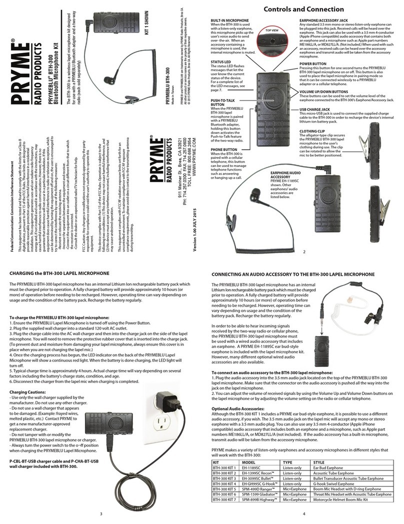
To connect the speaker microphone to the radio:
For dual-pin models (GPS-2201)
* Insert the speaker/microphone plugs into the speaker/microphone jacks of the transceiver.
* Push the connector toward the transceiver until you feel it “snap” into place.
* To prevent the connector from accidentally coming unseated during use, you may optionally
install the Kenwood locking bracket which is supplied with the transceiver.
For multipin models (GPS-2211)
* Insert the guide tab of the Trooper II GPS’s radio connector into the slot just below the radio’s
universal connector.
* Align the connector with the radio’s universal connector.
* Tighten the thumbscrew on the connector to secure it to the radio. Do NOT over tighten.
NOTE: You should ensure that the two-way radio is powered o whenever you connect/disconnect the
PRYME Trooper II GPS speaker microphone from the two-way radio.
Operation of the Trooper II GPS is transparent to the user. The user may transmit voice messages by
pressing and holding the Push-To-Talk button on the side of the Trooper II GPS and then speaking into
the microphone. Received calls will be heard Trooper II’s front-ring speaker or through the optional
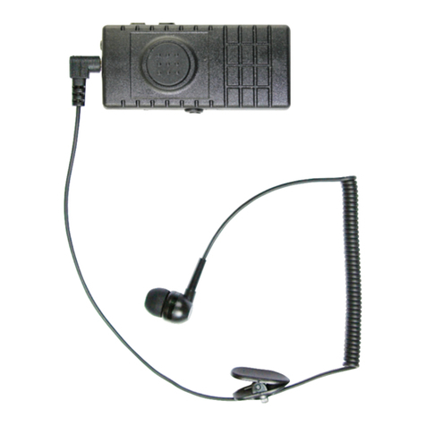
listen-only earphone, if one is used.
As long as the Trooper II GPS is connected to the radio’s accessory jack, the radio is powered on, and the
GPS receiver inside the Trooper II GPS has a valid location x, the user’s GPS coordinates will be sent as
data across the radio system at the pre-programmed intervals. The user can also manually send their
GPS location by selecting the “Send the GPS Data” option from the radio’s menu.
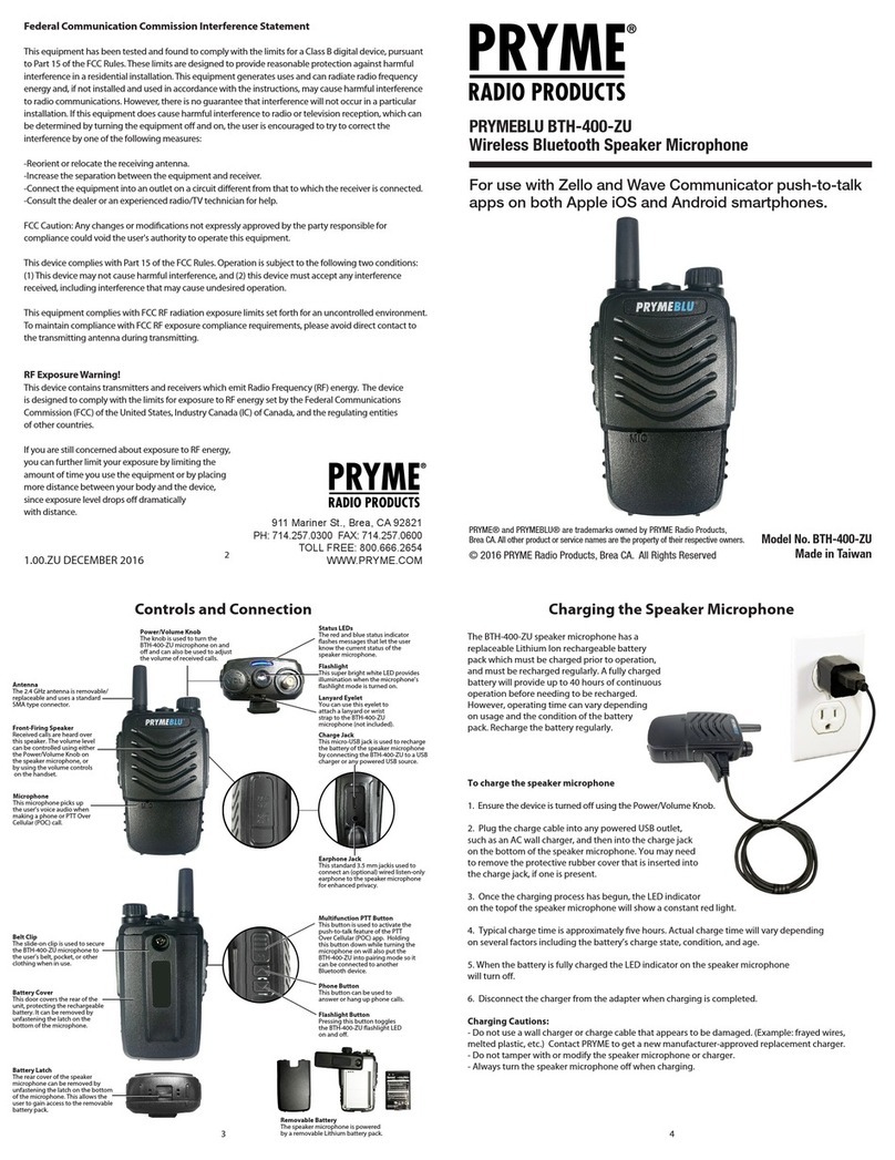
Note: GPS-2211 model shown.
Other models may vary slightly in appearance.
Radio Connector
This port allows the
speaker microphone to
connect to a compatible
Kenwood 2-way radio.
Microphone Cable
The Trooper II GPS uses PRYME’s
military-grade RINO™ microphone
cable. The cable has a tough
polymer jacket on the outside and
Kevlar® reinforcement inside and is
engineered to last longer and retain
its shape better than other cables.
Listen Only Earphone Jack
The microphone uses a standard
3.5 mm mono earphone jack for
connecting an optional listen-only
accessory (sold separately).
Swivel Clip
The metal-reinforced 360°
rotating clip allows the user
to secure the microphone to
their clothing.
Rubberized Grips
The grips on each side of the
GPS-2200 Trooper II™ make it easier
to hold the microphone
Push-to-Talk Button
Pressing and holding this button
causes the two-way radio to
transmit. The large PTT button is
easy to operate even when
wearing gloves.
Speaker
Received signals are
heard over the loud,
front-ring speaker.
Polycarbonate Housing
The weatherized housing is made
of durable high-impact
polycarbonate. It meets the
requirements for MIL-STD-810 and
has an IP56 rating against dust
and moisture.
Noise Cancelling Microphone
The noise cancelling microphone reduces
the amount of background noise
transmitted over-the-air, making the user’s
voice clearer and easier to understand, even
in high-noise environments.
GPS Antenna (Internal)
The Trooper II™ GPS uses an internal high-gain “stealth” GPS antenna.
Placing the antenna inside the microphone results in a more durable
design and prevents the GPS antenna from drawing attention.
These settings allow the radio to provide power to the GPS receiver in the PRYME Trooper II GPS.
In order for the GPS receiver in the Trooper II GPS to work properly, the two-way radio that the
speaker microphone will be used with must be properly programmed using the appropriate
Kenwood CPS (Computer Programming Software) and programming cable.
NOTE: The information in this section pertains to Kenwood Nexedge NX-200 and NX-300 radios.
Other radio models may require slightly dierent programming.
1. On the Tools > Extended Function screen set the following:
Universal Connector Pin Number 11 Function: Always 5V (high)
Output Control by SSW Checked or Unchecked
