manuals.online logo
Brands
  1. Home
  2. •
  3. Brands
  4. •
  5. Isolite
  6. •
  7. Safety Equipment
  8. •
  9. Isolite Max 2.0 Series User manual

Isolite Max 2.0 Series User manual

Other Isolite Safety Equipment manuals

Isolite MAX User manual

Isolite

Isolite MAX User manual

Isolite LPX-CT User manual

Isolite

Isolite LPX-CT User manual

Popular Safety Equipment manuals by other brands

Lanex PB-20 instruction manual

Lanex

Lanex PB-20 instruction manual

SKYLOTEC ANCHOR ROPES Instructions for use

SKYLOTEC

SKYLOTEC ANCHOR ROPES Instructions for use

Besto Buoyancy Aid 50N Instructions for use

Besto

Besto Buoyancy Aid 50N Instructions for use

TEUFELBERGER NODUS Manufacturer's information and instructions for use

TEUFELBERGER

TEUFELBERGER NODUS Manufacturer's information and instructions for use

Troy Lee Designs Tbone Product owners manual

Troy Lee Designs

Troy Lee Designs Tbone Product owners manual

Innova Xtirpa Instruction and safety manual

Innova

Innova Xtirpa Instruction and safety manual

bolle SAFETY B810 quick start guide

bolle SAFETY

bolle SAFETY B810 quick start guide

SHENZHEN FANHAI SANJIANG ELECTRONICS A9060T instruction manual

SHENZHEN FANHAI SANJIANG ELECTRONICS

SHENZHEN FANHAI SANJIANG ELECTRONICS A9060T instruction manual

Hiltron security POWER8E Installation and use manual

Hiltron security

Hiltron security POWER8E Installation and use manual

Salewa MTN SPIKE user manual

Salewa

Salewa MTN SPIKE user manual

Hatco B-950P installation guide

Hatco

Hatco B-950P installation guide

Sitec TX MATIC operating manual

Sitec

Sitec TX MATIC operating manual

TEUFELBERGER GRIP 12 Manufacturer's information and instructions for use

TEUFELBERGER

TEUFELBERGER GRIP 12 Manufacturer's information and instructions for use

MSA PremAire System Operation and instructions

MSA

MSA PremAire System Operation and instructions

AMC 1022M Series instruction manual

AMC

AMC 1022M Series instruction manual

Trinity CASS S3 Assembly manual

Trinity

Trinity CASS S3 Assembly manual

CMC Helitack HotSeat quick guide

CMC

CMC Helitack HotSeat quick guide

ACM SAFETY D200 Instructions and warnings

ACM

ACM SAFETY D200 Instructions and warnings

manuals.online logo
manuals.online logoBrands
  • About & Mission
  • Contact us
  • Privacy Policy
  • Terms and Conditions

Copyright 2025 Manuals.Online. All Rights Reserved.

INSTRUCTIONS
Max 2.0 Series
Wet Location LED Exit Sign
120/277VAC
IMPORTANT SAFEGUARDS
When using electrical equipment, basic safety precautions should always be followed including the following:
1. READ AND FOLLOW ALL SAFETY INSTRUCTIONS
2. Disconnect power before performing work on electrical equipment.
3. Use caution when servicing batteries.
4. Equipment should be mounted in locations and at heights where unauthorized personnel will not readily subject it to
tampering.
5. The use of accessory equipment not recommended by Manufacturer may cause an unsafe condition, and
will void the unit’s warranty.
6. Do not use this equipment for other than its intended purpose.
7. Servicing of this equipment should be performed by qualified service personnel.
8. SAVE THESE INSTRUCTIONS!
Headquarters: Isolite 31 Waterloo Avenue, Berwyn, PA, 19312 Phone: (610) 647-8200 Fax: (610) 296-8952
Western Office: Isolite 3563 Sueldo Suite M, San Luis Obispo, CA 93401 Phone: (800) 799-5343 Fax: (805) 546-9564
Chassis GND LED Board
AC ONLY SIGN
Chassis GND
GREEN Ground
BLACK 120VAC
RED 347VAC or ORANGE 200-277VAC
WHITE Neutral
LED Board
AC & UNIVERSAL DC SIGN
YELLOW Positive 6 to 24VDC
PURPLE Negative
Emergency Supply
FROM Battery Pack
SELF-POWERED SIGN
Chassis GND
24 hours
Unswitched Supply
GREEN Ground
BLACK 105 to 360VAC
WHITE Neutral
LED Board
DUAL UNIVERSAL AC SIGN
From Generator OR
Emergency Supply
BROWN 105 to 360VAC
BLUE Neutral
NOTE: Cap unused AC Wire!
24 hours
Unswitched Supply
GREEN Ground
BLACK 120VAC
RED 347VAC or ORANGE 200-277VAC
WHITE Neutral
24 hours
Unswitched Supply
Chassis GND LED Board
NOTE: Cap unused AC Wire!
GREEN Ground
BLACK 120VAC
RED 347VAC or ORANGE 200-277VAC
WHITE Neutral
24 hours
Unswitched Supply
Ni-Cd
Battery
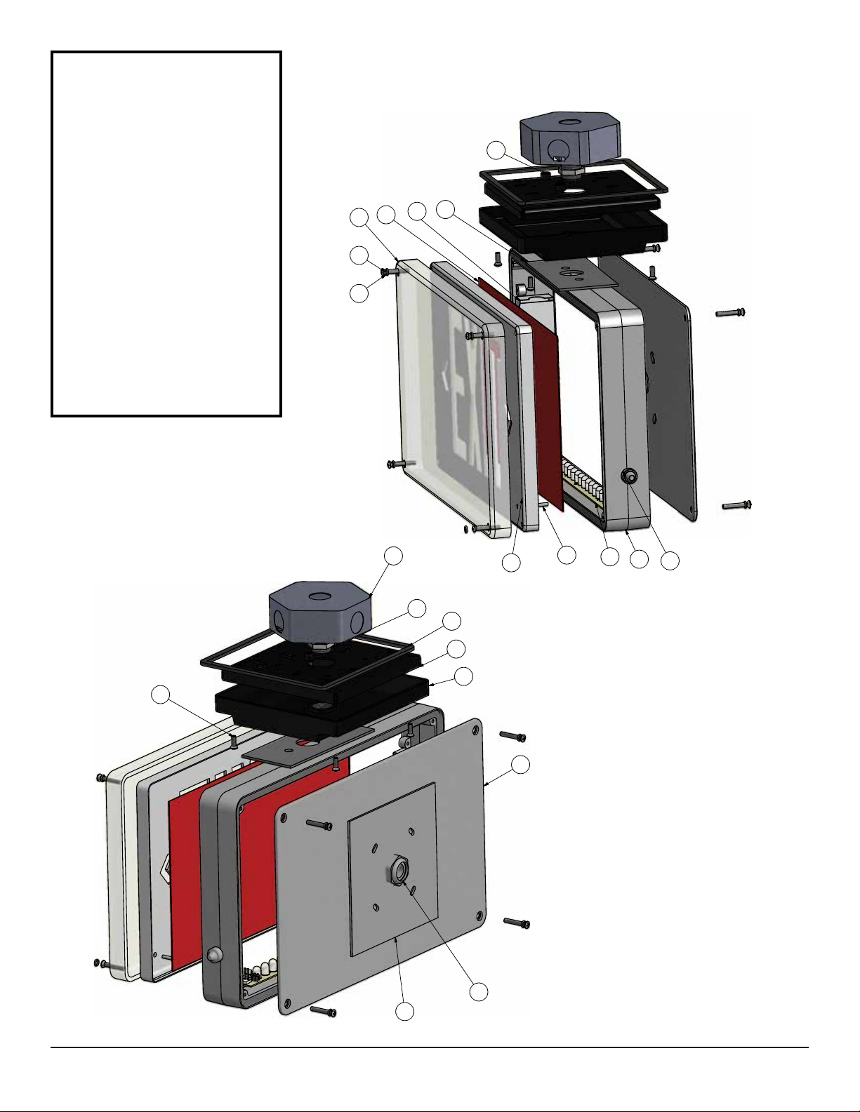
CEILING/END MOUNT INSTALLATION
WALL MOUNT INSTALLATION:
1. Remove torx screws (9) to release clear cover (1). There are 4 O-rings (10) inserted to the clear cover screw holes.
Release the stencil (2) from the clear cover (1). Knockout to remove the chevron as necessary from the stencil.
Peel off backing paper from the tape on the back of the stencil and carefully position and stick the colored fibre to the
stencil.
2. To install canopy kit, knockout on the top (for ceiling mount) or the knockout on the side (for end mount). Position
canopy gasket and the canopy (14). Install the cap screws and the washers. Attach canopy nuts and then tighten.
Install the liquid tight bushing (12), feed the lead wired through the bushing and tighten to complete the liquid tight
seal. Install the canopy mounting base (15) to the octagon box (11) (not supplied). Connect wires per diagram
provided. Caution! Failure to insulate unused wire may result in a shock hazard or unsafe condition as well as
equipment failure. The mounting base can be rotated for the desired mounting angle. Install the canopy (14) to the
mounting base (15) with the supplied screws.
3. Note: When installing the cover, be sure to align the light pipe (5) and LED indicator.
4. Apply power.
SELF-POWERED:
1. For models Max-SP, plug the battery into the circuit board per (wiring diagram) self-powered sign.
MAINTENANCE
1. Clean face(s) on a regular basis.
NOTE: The servicing of any parts should be performed by qualified service personnel only. The use of replacement
parts not furnished by Manufacturer may cause equipment failure and will void the warranty.
WIRING DIAGRAM
1. Remove torx screws (9) to release clear cover (1). There are 4 O-rings (10) inserted to the clear cover screw holes.
Release the stencil (2) from the clear face cover (1). Knockout to remove the chevron as necessary from the stencil.
Peel off backing paper from the tape on the back of the stencil (2) and carefully position and stick the colored fibre to
the stencil.
2. Remove the back plate (16) knockouts using applicable knockout holes. Install the liquid tight bushing into the large
centre knockout with the lock nut (12). Feed the lead wires through the bushing, tighten to complete the liquid tight
seal and install the wall gasket (18) then secure the back plate and housing to the wall. Connect wire per wiring
diagram provided. Caution! Failure to insulate unused wire may result in a shock hazard or unsafe condition as
well as equipment failure.
3. Replace faceplate, clear cover and torx screws. Note: When installing the cover, be sure to align the light pipe (5) and
LED indicator.
4. Apply power.
Headquarters: Isolite 31 Waterloo Avenue, Berwyn, PA, 19312 Phone: (610) 647-8200 Fax: (610) 296-8952
Western Office: Isolite 3563 Sueldo Suite M, San Luis Obispo, CA 93401 Phone: (800) 799-5343 Fax: (805) 546-9564
Parts List
DESCRIPTIONITEM
CLEAR COVER
1
STENCIL2
FRAME
3
FIBER4
LIGHTPIPE5
LED BOARD6
TEST SWITCH7
CEILING MOUNT GASKET8
TAMPER PROOF SCREWS9
O-RING10
OCTAGON BOX(SUPPIED BT OTHERS)
11
BUSHING12
CANOPY GASKET13
CANOPY14
CANOPY MOUNTING BASE
15
BACK PLATE16
CAP SCREWS
17
WALL MOUNT GASKET18
OVAL HEAD SCREWS19
BATTERYBOX20
1
1
2
2
3
3
4
4
A A
B B
C C
D D
This document is the property of and contains information proprietary to Beghelli Canada, Inc. It is submitted in confidence and is to be used solely for the
purpose for which it was furnished and returned upon request. This document and such information is not to be reproduced, transmitted, disclosed, or used
otherwise in wholeor in part without prior authorization of Beghelli Canda, Inc. The recepient's acceptance of this document shall be considered an
agreement to the foregoing.
UNLESS OTHERWISE SPECIFIED
ALL DIMENSIONS = INCHES
ANGLES +1/2
TOLERANCES:
.X = .020
.XX = .010
.XXX = .005
.XXXX = .003
3900 14Th. Avenue
MarkhamOntario, L3R 4R3
Tel. # 905 948-9500 Fax # 905 948 8673
email: sales@beghellicanada.com
Web: http://www.beghelli.com
MATERIAL
FINISH
DRAWN BY DATE
SIZE SCALE
REV
SHEET
PART NAME
DWG NO
REF NO
DO NOT SCALE
FTZ plus ASSY
6/14/2013
PART #
L D
9
10
1
2
4
7
18
16
11
12
13
14
8
63
15
19
20
17
5
12
Figure 1
PARTS LIST
1. Clear Cover
2. Stencil
3. Frame
4. Fiber
5. Lightpipe
6. LED board
7. Test switch
8. Ceiling mount gasket
9. Tamper proof screws
10. O-ring
11. Octagon box (not supplied)
12. Bushing
13. Canopy Gasket
14. Canopy
15. Canopy mounting base
16. Back plate
17. Cap screws
18. Wall mount gasket
19. Oval head screws
20. Battery box
Headquarters: Isolite 31 Waterloo Avenue, Berwyn, PA, 19312 Phone: (610) 647-8200 Fax: (610) 296-8952
Western Office: Isolite 3563 Sueldo Suite M, San Luis Obispo, CA 93401 Phone: (800) 799-5343 Fax: (805) 546-9564