manuals.online logo
Brands
  1. Home
  2. •
  3. Brands
  4. •
  5. MSA
  6. •
  7. Safety Equipment
  8. •
  9. MSA Kwik Draw User manual

MSA Kwik Draw User manual

Airtester HP
(Multiport Sampling)
for compressed air according to EN 12021
Instruction for use
Part Number D3188702 (Edition 1 Aug 15)
- 1 -
Manufactured by
Uniphos Envirotronic Pvt. Ltd.
Nahuli (PO), Valsad (Dist),Gujarat-396108, INDIA
For Assistance, Call on +91 2261233500
E-mail: [email protected]
www.uniphos-she.com
7
TABLE OF CONTENTS
1.
2.
3.
4.
5.
5.1
5.2
5.3
5.4
6.
6.1
6.2
7.
Use
Measuring Principle
Design
Technical Data
Operating Instruction
Preparing for Measuring
Measuring on Compressed Gas Cylinders
Measuring on Compressors
Premissable Test Results
Maintenance
General
Disorders
Part Numbers
Page
3
3
3
3
4
4
4
4
4
6
6
6
6
Notice!
Like any piece of complex equipment, this product will do the job designed to do only if it is used and serviced in
accordance with the manufacturer’s instructions.
- 2 -
This manual must be carefully read by all individuals who have or will have the responsibility for using or
servicing the product. Before choosing and using this product, it is required to assess whether this product is
suitable for the application intended. Choice and use are beyond the control of MSA AUER GmbH. Therefore,
the liability of MSA AUER GmbH covers only the consistent quality of this product. The above does not alter
statements regarding the warranties and conditions of sale and deliveries of MSA AUER GmbH.
KWIK DRAW UNIPHOS
Airtester HP (Multiport Sampling)
for compressed air according to EN 12021
Instruction for use
1. Use
The compressed air monitoring set “KWIK DRAW
UNIPHOS Airtester HP” (HP = high pressure) is used
to determine the content of carbon monoxide, carbon
dioxide, oil and water vapour in respirable air from
compressors and compressed gas cylinders. .
According to EN Standard 12021 air for respiratory
equipment must meet the following quality
requirements:
CO content max. 15 ppm
CO content max. 500 ppm
2
Free of odor and taste, i.e. practically free of
critical mineral oil content (from experience the oil
content is less than 0.5 mg/m³)
Water content in compressed air cylinders:
max. 50 mg/m³ at a charging pressure of 200 bar
max. 35 mg/m³ at a charging pressure of 300 bar
max. 25 mg/m³ of the air from the compressor
-
-
-
-
The requirements concerning the maximum water
vapour content refer to the type of equipment used
(200 or 300 bar) and, therefore, apply also to each
pressure level of the compressed gas cylinders
below the maximum values given above. .
All maximum values are based on air not under
pressure.
2. Measuring Principle
3. Design
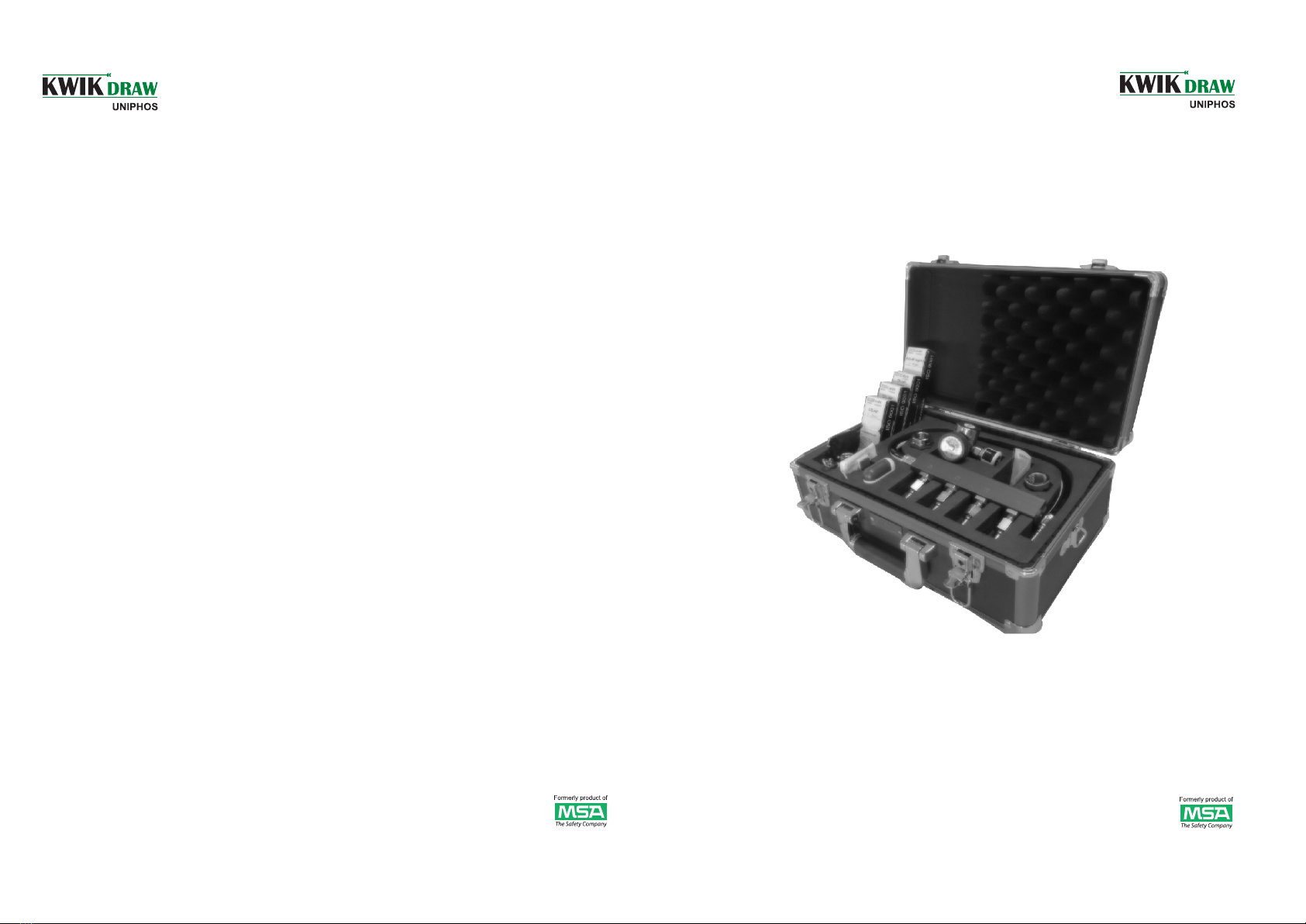
The case contents all parts required for measuring
(see fig. 1):
-
The standard case contents one package of each of
- 3 -
Fig. 1 KWIKDRAW UNIPHOS Airtester HP
4. Technical Data
Measuring ranges of the Detector Tubes:
Carbon monoxide detector tubes
5 to 70 ppm carbon monoxide at a flow rate of
0.3 l/min in a measuring time of 5 minutes. (required
sampling volume 1.5 l).
See also specific instructions for use of the KWIK
DRAW / MSA AUER detector tubes CO-HP.
Carbon dioxide detector tubes
100 to 2000 ppm carbon dioxide at a flow rate of
0.3 l/min in a measuring time of 5 minutes. (required
sampling volume 1.5 l).
See also specific instructions for use of the
KWIK DRAW / MSA AUER detector tubes CO2-HP.
Oil detector tubes
This type of tube indicates semi-quantitatively mineral
and synthetic Oils.
Check for oil contents (vapor + mist) at a flow rate of
2.5 l/min in a measuring time of 24 minutes. (required
sampling volume 60 l). The content of oil is determined
as per the instruction given to use the KWIK
DRAW / MSA detector tube Oil-HP Synth.
the four types detector tubes. In addition, the case
has space for storing four additional spare
packages.
air
300 + 30 bar
0.3 , 1.0 and 2.5 l/min.
(The detector tubes are to be
fitted in an appropriate port of
manifold to pass required
sample air.)
5 kg
h= 120; w= 320; l= 420 mm
Operation medium:
Maximum pressure:
Flow:
Weight (with case):
Dimensions:
- 6 -
6. Maintenance
6.1 General
In view of the significance of the accuracy of
measuring results, the test device must be treated
with care. Dirt must be avoided at all time, especially
at the high-pressure connection.
Flushing and cleaning of the test device must be
made as described in para. 5.2. After measuring is
completed, the test device shell is stored in the case.
The high pressure connection should be closed with
a protective cap.
Function checks should be made at regular intervals
and if erroneous measurements are suspected.
6.2 Disorders
If the hand wheel of the test device cannot be
loosened while it is connected to a compressed gas
cylinder or compressor, check if connection is under
pressure. In this case close the cylinder valve or
compressor valve and release air from test device.
Leaks at the connection to the cylinder or
compressor could be due to a defect gasket. In this
case replace the gasket.
If the high pressure gauge or the detector tube holder
is defective, they must be replaced.
In case of other disorders the device should be
returned for repair to UNIPHOS or any authorized
service station.
7. Part Numbers
KWIK DRAW UNIPHOS Airtester HP
(Compressed air monitoring set)
Complete with case containing:
Test device consisting of pressure reducer with
high pressure gauge, manifold, flow meter detector
tube holder.
Adapter for 200 and 300 bar one each for connecting
to compressor charging panel
Timer
Device for breaking off detector tube tips,
Detector tubes for measuring carbon monoxide,
carbon dioxide, water vapor, oil - one package each.
Accessories and Spare Parts
Detector tubes CO-HP*
Detector tubes CO -HP*
2
Detector tubes H O-HP*
2
* = Package of 10 pieces
D5085847
D5085848
D5085849
Detector tubes Oil- HP Synth.*
for testing of mineral and synthetic Oil
Pressure reducer with pressure gauge
Manifold
Gaskets-lifter
Detector tube holder
Timer
Tube tip breaking device
Case
Case insert
Flow meter
10040887
D4074937
CR001444
D4060241
D4074058
D5185020
D5085012
D5185911
D5185931
CR001452
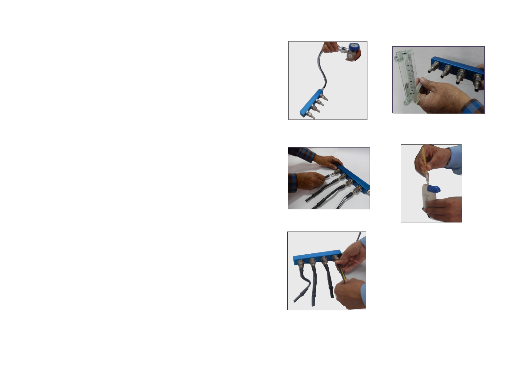
The pressure in the compressed gas cylinders, or
in the compressor charging panel is reduced by a
pressure reducer. The air to be sampled is taken
continuously via a regulatory valve in the manifold.
There are four outlets for this manifold which release
fixed flow rate of gas. The flow rate of each port is
printed on the body of the manifold, viz 0.3 l/min,
0.3 l/min 1.0 l/min and 2.5 l/min. The air coming out
from these ports is taken through detector tube for a
specific time. The length of stain in the detector tube
is an index of the concentration of the measured
substance. This can be read directly from the detector
tube scale.
The test device, consisting of pressure reducer,
Pressure gauge, manifold, flow meter, detector
tube holder, adapter for connection to a
compressor charging panel ( for charging
connection 300 or 200 bar), timer, detector tube
tip breaker, tubes (package of 10) for measuring
CO, CO2, water vapor and oil content (sum of
Oil vapor and mist). .
- 5 -
- 4 -
Water vapour detector tubes
20 to 160 mg/m3 water vapor at a flow rate of 1 l/min
and a measuring time of 5 min. (required sampling
volume 5 l) or 5 to 70 mg/m3 water vapor at a flow
rate of 1 l/min and a measuring time of
10 min. (required sampling volume 10 l).
See also specific instructions for use of the KWIK DRAW
/ MSA AUER detector tubes H O-HP.
2
All values above are based on air not under pressure
and at room temperature and normal pressure.
5. Operating Instruction
5.1 Preaparing for Measuring
5.2 Measuring on Compressed Air Cylinders
When the test device is clean and dry flushing for
2 min. is sufficient. If the condition of device is not
known, or if during a previous measurement higher
values were found than are permissible according to
EN 12021, flushing at 2 l/min. must be continued.
This must b e done until 2 w ater vapor
measurements, made at an interval of approx. 15
min., give identical results within the permissible
measuring accuracy range. It then can be assumed
that the test device is sufficiently clean for making
measurements. .
Liquid/ water (droplets) can only be removed from
the test device through long flushing with dry, if
necessary warm air. .
.
Observe arrow on the detector tube. The arrow
points in the flow direction of the test air; therefor,
after inserting the tube, the arrow must point away
from the test device. .
Clean valve of compressed gas cylinders or
charging connections of compressor with brief
burst of air. .
Chose and connect the adapter suitable for the
prescript maximum pressure of the compressor
charging panel (300 or. 200 bars). .
Connect pressure reducer to compressed gas
cylinder, or to charging connection of compressor
using the adapter. .
Insert and firmly fit the nozzle of manifold on the
pressure reducer as shown in fig. 2 .
.
.
-
-
-
-
-
-
-
-
-
Break off the detector tube tips at air exit side
(see fig. 5) .
Put detector tube into the tube holder, inserting
broken-off end tightly into holder side away from
test device. .
Break off other end of the detector tube (air entry
side) and immediately insert open tube tightly into
other end of detector tube holder (close to test
device). (see fig. 6). .
Immediately thereafter start the timer to the time
designated for the type of detector tube.
Remove the detector tube of CO, CO2 and H2O
after 5 minutes from the tube holder and take the
readings from the printed scale on the tube.
Remove the oil detector tube from the tube holder of
test device after 24 minutes and take the readings
from the printed scale on the tube.
5.3 Measuring on compressors
Switch on the compressor
Wait until 200 or 300 bar are reached
Switch off the compressor
Slowly open valve on compressor
Flush test device as scripted in para. 5.2
The water content that is measured in air from a
compressor only corresponds to the water content of
compressor gas cylinders simultaneously charged, or
cylinders charged immediately after measuring, if a
pressure retaining valve is built into the compressor at
the exit side of the drying cartridges. A prerequisite,
however, is that the cylinders to be charged are dry.
The pressure retaining valve assures that the pressure
inside the compressor drops only insignificantly from
the maximum pressure of 300 or 200 bar, when
cylinders are being charged. With compressor that has
no pressure retaining valve behind the filters, water
from the drying cartridge can be released to the
sudden decompression when the charging connection
is opened. The air has then higher water content as
was measured on the compressor charging panel. .
MSA AUER compressors normally have a pressure
retaining valve.
5.4 Permissable Test Results:
CO Contents
CO Contents
2
Oil Contents
Water Contents
max. 15 ppm
max. 500 ppm
max. 0.5 mg/m³
max. 50mg/m³ rel. to 200 bar)
max. 35 mg/m³ (rel. to 300 bar
max. 25 mg/m³ (if sampled from
compressor)
-
-
-
-
-
-
-
-
-
-
-
Fig. 2: Inserting manifold nozzle to
Pressure reducer coupling
Fig. 5: Breaking off detector tube tips
Fig. 6: Inserting detector tube into detector tube
holder
Slowly open cylinder valve. .
The flow rate of air through each port of manifold
can be confirmed if necessary by using the flow
meter provided with the kit. (To measure the flow
rate connect tubing of flow meter to the desired
manifold port- Fig:3) .
Insert the detector tube holders in the manifold
ports- Fig:4 .
Flush device for sufficient time to make the test
device free from other gases if any. .
.
Fig. 3: Connecting flow meter to
manifold port
Fig. 4: Inserting detector tube holder
in manifold port

This manual suits for next models

1

Other MSA Safety Equipment manuals

MSA left/RIGHT User manual

MSA

MSA left/RIGHT User manual

MSA PremAire Cadet Escape User manual

MSA

MSA PremAire Cadet Escape User manual

MSA Latchways SRL User manual

MSA

MSA Latchways SRL User manual

MSA 10207314 User manual

MSA

MSA 10207314 User manual

MSA SUPREMA User manual

MSA

MSA SUPREMA User manual

MSA Ultima X Series User guide

MSA

MSA Ultima X Series User guide

MSA PrimaX IR User manual

MSA

MSA PrimaX IR User manual

MSA FALL-RESCUE 10022050 User manual

MSA

MSA FALL-RESCUE 10022050 User manual

MSA Aptura LT30 User manual

MSA

MSA Aptura LT30 User manual

MSA PremAire System User manual

MSA

MSA PremAire System User manual

MSA G1 PremAire User manual

MSA

MSA G1 PremAire User manual

MSA SURETYMAN SRS15 Installation instructions

MSA

MSA SURETYMAN SRS15 Installation instructions

MSA BD mini User manual

MSA

MSA BD mini User manual

MSA fieldserver FS-8700-60 User manual

MSA

MSA fieldserver FS-8700-60 User manual

MSA Cairns XR2 User manual

MSA

MSA Cairns XR2 User manual

MSA FieldServer FS-8700-153 User manual

MSA

MSA FieldServer FS-8700-153 User manual

MSA FP Pro User manual

MSA

MSA FP Pro User manual

MSA fieldserver FS-8700-144 Release note

MSA

MSA fieldserver FS-8700-144 Release note

MSA SavOx User manual

MSA

MSA SavOx User manual

MSA ULTIMA X5000 User guide

MSA

MSA ULTIMA X5000 User guide

MSA Vautex Elite ET User manual

MSA

MSA Vautex Elite ET User manual

MSA NightFighter User manual

MSA

MSA NightFighter User manual

MSA alphaBELT Pro User manual

MSA

MSA alphaBELT Pro User manual

MSA PremAire System User manual

MSA

MSA PremAire System User manual

Popular Safety Equipment manuals by other brands

Kaya Safety rock RETRAC PS-10 user guide

Kaya Safety

Kaya Safety rock RETRAC PS-10 user guide

Petzl MICRO TRAXION quick start guide

Petzl

Petzl MICRO TRAXION quick start guide

Elysee 23474 manual

Elysee

Elysee 23474 manual

NOVOLUX ES725-VISERA.POLIC. instructions

NOVOLUX

NOVOLUX ES725-VISERA.POLIC. instructions

Dräger X-plore 8000 Instructions for use

Dräger

Dräger X-plore 8000 Instructions for use

Latchways CSA Z259.2.2-98 User instructions

Latchways

Latchways CSA Z259.2.2-98 User instructions

IDEC EB3P-ZN Installation

IDEC

IDEC EB3P-ZN Installation

ClimbTech SWHM39N Operation and instruction manual

ClimbTech

ClimbTech SWHM39N Operation and instruction manual

Camp Safety COBRA manual

Camp Safety

Camp Safety COBRA manual

CMC Rescue 3D Important information

CMC Rescue

CMC Rescue 3D Important information

PSS FRISTGARD FOLDABLE CONE Replacement instructions

PSS

PSS FRISTGARD FOLDABLE CONE Replacement instructions

HOLLISTER-WHITNEY ROPE GRIPPER instructions

HOLLISTER-WHITNEY

HOLLISTER-WHITNEY ROPE GRIPPER instructions

Tractel tirsafe T3 Operating and maintenance instructions

Tractel

Tractel tirsafe T3 Operating and maintenance instructions

Climbing Technology WORK TEC 140 manual

Climbing Technology

Climbing Technology WORK TEC 140 manual

Protekt AZ 002 Instructions for use

Protekt

Protekt AZ 002 Instructions for use

3M Protecta Trolmatic User instruction manual

3M

3M Protecta Trolmatic User instruction manual

EDELRID CABLE KIT LITE VI manual

EDELRID

EDELRID CABLE KIT LITE VI manual

Guardian 10785 instruction manual

Guardian

Guardian 10785 instruction manual

manuals.online logo
manuals.online logoBrands
  • About & Mission
  • Contact us
  • Privacy Policy
  • Terms and Conditions

Copyright 2025 Manuals.Online. All Rights Reserved.