PSA LIFESAVER 6000DCW User manual

1
Lithium (sealed non-replaceable)
Battery-Operated Photoelectric Smoke Alarm
with wireless RF Interlink and HUSH Control
You do NOT need a home Wi-Fi system to use
these units. Multiple wireless units create their
own independent wireless
RF interlink network.
Smoke Alarm with RF Interlink User Guide
Tested & Complies to
Australian Standards
AS3786:2014 AS 3786:2014
Lic:SMK1377
SAI Global
Model 6000DCW
Part Number: LIF6000DCW

2
Thank You for Purchasing this PSA Lifesaver Smoke Alarm
The smoke alarm you have purchased is capable of wirelessly interlinking with other Lifesaver
6000DCW smoke alarms and Lifesaver 6000 series mains powered smoke alarm fitted with 6000WB
wireless base, and 6000THL smoke alarm remote control. When one RF interlink unit sounds an alarm,
all other compatible RF units in the RF interlink network will alarm, the red LED on Remote Control will
blink.
Read Section 6: Activation And RF Interlink Network, before powering the units. You do
NOT need a home wi-fi system to use these units. Multiple wireless units create their own
independent RF interlink alarm network.
This smoke alarm and included RF module are powered by a non-replaceable, long life sealed lithium
battery system, which will last up to 10 years after power up (under normal operation).
NOTE: A NETWORK IS LIMITED TO 24 ALARMS
Teach children how to respond to the alarm and that they should never play with the unit.
Your PSA LIFESAVER Smoke Alarm was designed for use in a residential environment. It is not designed
for use in a recreational vehicle (RV) or boat.
Note: Please thoroughly read this user guide and save the document for future reference and
to pass on to any subsequent owner.
IMPORTANT: Additional markings can be found on the back or side of the unit.
Date Code (on back): ___________________
Date of Purchase: ___________________
Where Purchased: ___________________
Date to Replace: ___________________
Product Support: 1300 772 776
Please write down the following details, and
have the information at hand when you call us

3
Contents
1. Smoke Alarm: What To Do When The Alarm Sounds .....................................................................4
2. Other Alarm Visual and Audible Indications ................................................................................... 5
3. Introduction, Product Features And Specifications .......................................................................... 5
4. Recommended Locations For Alarms ...............................................................................................6
5. Locations To Avoid ......................................................................................................................... 8
6. Activation and RF Interlink Network ............................................................................................... 9
6.1 Setting Up an RF Interlink Network ..........................................................................................9
6.2 Adding Another Device to an Existing RF Interlink Network ....................................................10
6.3 Resetting a Device’s RF Interlink Settings ................................................................................11
7. Wireless FAQs................................................................................................................................12
8. Installation Instructions ................................................................................................................ 13
9. Operating, Testing and Alarm Characteristics ................................................................................15
10. Troubleshooting.............................................................................................................................16
11. Recognising Nuisance Alarms ........................................................................................................17
12. Battery ..........................................................................................................................................18
13. Permanently Disable Alarm / Discharge Battery .............................................................................19
14. Smoke Alarm Controller ............................................................................................................... 20
15. Cleaning Your Alarm .................................................................................................................... 21
16. Good Safety Habits ...................................................................................................................... 22
17. Limitations Of Smoke Alarms ....................................................................................................... 23
18. Warranty and Liability ...................................................................................................................24
19. Product warranty registration ....................................................................................................... 25

4
1. Smoke Alarm: What To Do When the Alarm Sounds
Smoke alarm pattern is three long beeps, a 1.5 second pause, and three long beeps repeating.
The red LED flashes every 0.5 seconds during alarm.
•Alert small children in the home as well as anyone else that might have difficulty recognizing the impor-
tance of the alarm sounding or that might have difficulty leaving the area without help.
•Leave immediately by your escape plan. Every second counts, so don’t waste time getting dressed or
picking up valuables.
•In leaving, don’t open any inside door without first feeling its surface. If hot, or if you see smoke seeping
through cracks, don’t open that door! Instead, use your alternate exit. If the inside of the door is cool,
place your shoulder against it, open it slightly and be ready to slam it shut if heat and smoke rush in.
•If the escape route requires you to go through smoke, stay close to the floor where the air is cleaner.
Crawl if necessary, and breathe shallowly through a cloth, wet if possible.
•Once outside, go to your selected meeting place and make sure everyone is there.
•Call the fire department from your mobile phone outside, or from your neighbour’s home-not from
yours!
•Don’t return to your home until the fire officials say that it is all right to do so.
•There are situations where a smoke alarm may not be effective to protect against fire.
For instance:
a) smoking in bed
b) leaving children home alone
c) cleaning with flammable liquids, such as petrol or methanol.
NOTE: See Section 11: RECOGNISING NUISANCE ALARMS, for nuisance alarm situations.

5
3. Introduction, Product Features And Specifications
Introduction
This alarm detects products of combustion using photoelectric technology. Ten (10) years after the unit is
installed, this unit will automatically alert you that it is time to replace the unit. To help track the life of your
alarm, write the installation date in the space provided on the back of the alarm.
Product Features and Specifications:
•Temperature: Operating Range: 0 °C to 45 °C
•Humidity: Operating range: up to 95% RH non-condensing
•Audible Alarm: 85+ dBA at 3m @ 3.0 to 3.5 KHz pulsing alarm
•Smoke Sensor: Photoelectric
•Smoke Alarm HUSH Control
•Smoke alarm powered by Panasonic/FDK 10 year 3VDC CR17335 battery.
•RF powered by Panasonic/FDK 3VDC CR17455 battery
•Supervised wireless network
•Radio Frequency 918MHz.
•Wireless interconnectable to other compatible alarms (RF Interlink). Range: 100m line of sight. 30m
indoors. Distances will vary depending on walls and obstructions.
•Insect mesh protection over sensor.
2. Other Visual And Audible Indications
The following tables describes visual and audible indications the unit may emit during normal operation.
Mode
LED
Indications
Audible
Indications Note:
Standby None None
Smoke Alarm Hush Flash every
10 seconds
None (smoke alarm silenced) Alarm hush feature silences
smoke alarm for approx. 10
minutes.
Push to Test (hold
button for up to
5 seconds)
Flash every 0.5 seconds Two sets of 3 long beeps (on
all RF interlinked units)
Press & HOLD button; first T3*
pattern is at low volume, If
interlinked to other RF devices,
it may take up to 20 seconds
to activate other RF interlinked
units in the network.
* T3 pattern: 3 long beeps of alarm(ISO 8201).

6
4. Recommended Locations For Alarms
NOTE: If possible, it is best to locate the Coordinator in a central location of your residence,
and then use the following guidelines for RFD unit placements. See section 6 for a
definition of “Coordinator” and “RFD”.
• Check specific State legislation in your area to ensure smoke alarms are correctly located
according to local laws. Each State or Territory may differ in building codes and regulations.
PSA Products can only recommend the locations.
• Locate an alarm for each separate sleeping area in the immediate vicinity of the bedrooms.
Try to monitor the exit path as the bedrooms are usually farthest from an exit. If more than one
sleeping area exist, then install additional alarms in the immediate vicinity of each sleeping area.
• Locate additional alarms to monitor any stairwell because stairwells act like chimneys for smoke
and heat.
• Locate at least one alarm on every floor level.
• Locate an alarm in every room where a smoker sleeps.
• Locate an alarm in every room where electrical appliances are operated (i.e. portable heaters or
humidifiers).
• Locate an alarm in every room where someone sleeps with the door closed. The closed door
may prevent an alarm not located in that room from waking the sleeper.
• Smoke, heat and other combustion products rise to the ceiling and spread horizontally.
Mounting the alarm on the ceiling in the center of the room places it closest to all points in the
room. Ceiling mounting is preferred in ordinary residential construction..
• When mounting alarms on the ceiling locate it at least 300mm away from the side wall and
300mm away from any corner. (see diagram).
• When mounting alarms on a wall, use the inside wall. The recommended position is between
300mm and 500mm off the ceiling. (see diagram).
NOTE: The performance of smoke alarms mounted on walls is unpredictable and this
mounting position is not recommended when ceiling mounting can be implemented.

7
IMPORANT: Incorrect orientation of smoke alarm may decrease operational effectiveness
Typical Multiple Floor Installation
Location of smoke alarm
Apex Of Sloping Ceiling Ceiling / Wall Junction
Single Floor
Smoke alarms for minimum protection
Smoke alarms for additional protection

8
5. Locations To Avoid
• Do not locate your smoke alarm in the garage - products of combustion are present when you
start your automobile. Use Lifesaver Heat Alarm in this location.
• Do not locate your alarm in front of forced air supply ducts used for heating and air conditioning
and other high air flow areas.
• Do not locate your smoke alarm less than 500mm from the peak of an “A” frame type ceiling.
• Do not locate your smoke alarm in areas where temperatures may fall below 0°C or rise above
40°C, or in humidity higher than 95% as these conditions may reduce battery life.
• Avoid dusty areas, dust particles may cause smoke alarm to false alarm or fail to alarm. Use
Lifesaver Heat Alarm in this location to avoid false alarms.
• In dusty areas, dust particles may cause nuisance alarm or failure to alarm.
• Avoid very humid areas or near a bathroom, moisture can cause false alarm.
• Avoid insect-infested areas.
• Do not locate alarm within 0.9m of the following: the door to a kitchen, the door to a
bathroom containing a tub or shower, ceiling or whole house ventilating fans, or other high
flow areas.
• Avoid locating near fluorescent lights or other electrical equipment. Electronic magnetic
interferences or “noise” may cause nuisance alarms or chirping.
• Smoke alarms are not to be used with detector guards unless the combination (alarm and guard)
has been evaluated and found suitable for that purpose.

9
6. Activation and RF Interlink Network
This model is capable of interlinking with other PSA 6000DCW alarms in domestic residential
applications. When one RF interlink unit sounds an alarm, all other compatible RF units in the RF
interlink network will alarm. Follow the steps in section 6.1 to interlink up to 24 units in your interlink
network. If you have problems during setup, see section 6.3 to start over.
NOTE : Wireless units will emit a series of LED flashes and beeps as the unit(s) search for an RF
interlink network. If you are intending to use wireless units without the wireless function, ignore these
notifications, and the wireless function will eventually turn off. You can turn the wireless function on
again at a later date if desired. See Section 6.2.
NOTE : The battery is switched ON when the smoke alarm is installed onto its mounting plate; and
turned OFF when the device is removed from its bracket. See Permanently Disable Alarm / Discharge
Battery section13.
Definitions of key terminology:
Coordinator: The wireless network master unit that is the key communicator with the other wireless
units. This assignment remains until the Coordinator is reset (section 6.3).
IMPORTANT: The Coordinator unit should be installed in a central location of the residence.
RF Device (RFD): The other wireless units that connect to the Coordinator.
General Reset mode: Resets a unit to when it was powered on for the first time after being removed from the
package.
6.1 Setting Up an RF Interlink Network
For easy first time setup, we recommend unpacking all the units together on a table. If you prefer
to install the alarms on the ceiling before setting up the wireless network, then first attach all the
mounting brackets to the ceiling. Next, choose the most centrally located unit and begin with Step 2
below.
User Input Detector Response Timeout
Step 1 Unpack all units
Step 2 Power up the first unit by rotat-
ing the unit onto its mounting
bracket.
Unit powers up - Red LED one
second on one second off, and
one chirp
Step 3 2 Button Presses on First Unit 2 soft beeps and two quick Red LED
flashes every 2 seconds to indicate
unit is configured as a Network
Coordinator and a sonar ping sound
indicates that Join Mode is Open
Join Mode will timeout in 15 minutes

10
6.2
Adding A Detector To An Existing RF Interlink Network
In future, you might want to add another 6000DCW unit to your existing RF interlink network for
additional protection, or to replace an old unit. Follow the steps in the following table.
User Input Detector Response Timeout
Step 1 2 Button Presses on Any Unit
in the Network
The Coordinator will flash twice
every 2 seconds. A RFD unit will flash
three times every 2 seconds. And the
sonar-pinging sound indicates the
Network is in Join Mode.
Join Mode will timeout in 15
minutes
Step 2 Power up unit(s) being added
by attaching the unit(s) to
the mounting bracket(s). For
previous units that have been
reset, press button twice to
enter Join Mode.
Unit will produce Tweedle sound when
it joins, then Red LED flashes three
times every 2 seconds to indicate it is
configured (as an RFD) in the network
Join Mode will timeout in 15
minutes
Step 3 After new unit(s) have joined,
press button twice on any
unit in the network to close
Join Mode.
Red LED on each unit will power off
indicating Standby Mode
Join Mode will timeout in 15
minutes
Step 4 Follow installation instructions
in Section 8.
User Input Detector Response Timeout
Step 4 Install each additional unit, one
at a time, onto its mounting
bracket.
Red LED on each unit will initially flash
one second on and one second off.
Tweedle will sound when each unit
joins network and red LED flashes three
times every 2 seconds to indicate it is
configured as a RFD in the network
Join Mode will timeout in 15 minutes
after last unit joins.
Step 5 After all units have joined, press
button twice on last unit.
Red LED on each unit will power off
indicating Standby Mode
Step 6 Follow installation instructions
in Section 8.

11
6.3 Resetting A Unit’s RF Interlink Feature (General
Reset mode)
This section will explains how to perform a general reset of a unit, which starts the unit over as if it
were powered up for the first time. It also explains how to remove a unit from a network if needed.
Follow the steps in the table below if one of these conditions occurs:
* If you have problems connecting the 6000DCW to a wireless network; Or if the network
configuration has become confused.
* If a unit has reached its end of life or has a low battery, and needs to be removed from the RF
Interlink Network.
* If a unit is consistently out of range and needs to be removed from the RF Interlink Network.
* If you are transferring a 6000DCW from your network to another wireless network (eg. at your
friend’s or family’s place).
User Input Detector Response Timeout
Step 1 Press button twice quickly to enter Join
Mode.
Network enters Join Mode:
Its Red LED will flash either:
* Twice every 2 seconds - as Coordinator
* Three times every 2 seconds - as RFD
* 1 second ON & 1 second OFF - when searching for network
Also, Sonar Ping sounds from the unit which opened the
Join Mode.
Step 2 Press and Hold Button on unit to reset
or remove.
Red LED will blink four times, twice - indicating the unit has
been reset. Unit is in general reset condition and is now in
stand alone mode. Unit will not join a network until network
opened at this specific unit with two button presses.
Step 3 2 button presses on any other unit in the
network to close Join Mode.
Red LED on each unit will turn off indicating Standby Mode
Step 4 a. If trying to join a network, start over
with section 6.2. If problems still occur,
call Product Support.
b. If unit has reached end of life or has a
low battery, proceed to Section 13.

12
7. Wireless FAQs
ID FAQ Answer
1Can the wireless units be connected
together (on the bench) before
installing them?
Yes, 6000DCW smoke alarms can be paired together before installing
them onto the ceiling. See Section 6.1 for details.
2What happens if units are powered
up for the first time but no buttons
are pressed?
Units will search for a network for 15 minutes after which all units will go
into standby mode. To recover, two quick button presses to restart join
mode on all units that have timed out.Return to section 6.1.
3What happens if a unit doesn’t
find a network during the joining
process (out of range, defective
radio, not made coordinator)
Unit will go into Standby mode. Ensure the Coordinator is mounted in a
central position. Confirm suitable operating environment: eg. RF range
not exceeded, nor any obstructions to RF signal.
4How can a unit be added to the
network?
Push button twice on any existing networked unit. Power on new unit
and wait for it to join. Push any button twice to close network. See
section 6.2.
5Can the joining process be
reset/restarted?
Yes. Push button twice to open network. Push/hold button for approx 4
seconds until two beeps. Push button twice to reopen network at that
unit. See section 6.3.
6Is there a way to get more informa-
tion about a trouble status?
In Alarm Fault mode, press button for Red LED error code. Count the
number of Red LED flashes and contact Product Support.
7What happens if the User created
two Coordinators during Joining
Mode?
Each network can only have one Coordinator. See Section 6.3 to reset one
of the Coordinators, and to make it a RFD unit.
8How do I check the number of
joined units in the network?
While in Join Mode, press and release button on any joined unit. LED will
blink out number of units.
9Is it possible to check if a unit is the
Coordinator or a RFD?
Press the button quickly twice to enter Join Mode. The Red LED flash
pattern will identify whether it is a Coordinator or a RFD unit. If it is a
Coordinator, it will flash twice every 2 seconds. Or it will flash three times
every 2 seconds as a RFD unit.
13
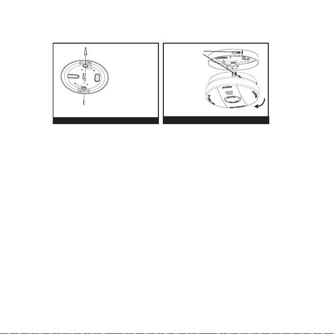
8. Installation Instructions
After selecting the proper smoke alarm location as described in Section 4, attach the mounting
bracket to the ceiling as shown in Figure 4. Use the screws and cavity fixings provided to secure
the mounting bracket (use 5mm drill bit for cavity fixings.)
Install the alarm on the mounting bracket (Figure 5) and gently rotate the alarm clockwise (as
indicated on the alarm cover) until the alarm snaps into place and beeps once. The smoke alarm
will only install onto the mounting bracket in one direction. Use the alignment indicator.
The alarm is now activated!
After installation/activation, test your alarm as described Section 9 (Operation & Testing).
IMPORTANT: Removing the smoke alarm from its mounting bracket will de-activate the unit.
Figure 4
Figure 5
When mounting
inahallway, the
“A” line should
be perpendicular
to the hallway.
Align the arrow
and alignment
mark on the side
of alarm. Turn
clockwise to
mount.
Install
AA
Figure 4
14
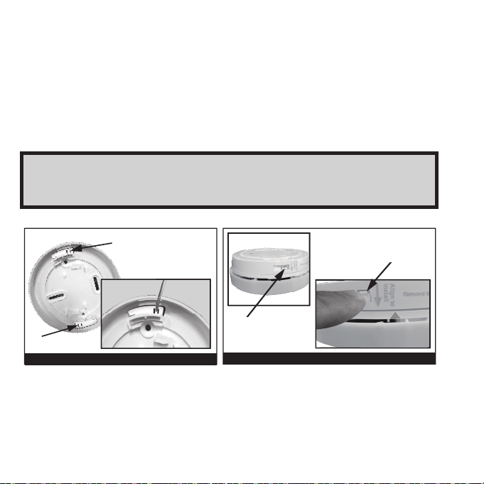
Smoke Alarm Tamper Resist Feature
This alarm is equipped with a tamper resist feature that helps prevent someone from removing the
unit from the mounting bracket. When activated, it can be very effective in preventing smoke alarm
removal or tampering. Activate the smoke alarm tamper resist feature by removing the small middle
tab on both the Tamper Tabs (see Figure 6). When the tab is broken off, the tamper on the base is
allowed to engage the mounting bracket. Rotate the alarm onto the mounting bracket until you hear
the tamper resist tab snap into place, locking the alarm on the mounting bracket. Using the tamper
resist feature will help deter children and others from removing the alarm from the bracket.
Figure 6
Figure 7
Tamper unlock
Press down
the tab to unlock
Tamper tab
Tamper tab
Maintenance Feature
For an annual maintenance check, press and hold the TEST button. If the unit flashes its Red LED five
times, then the alarm batteries and/or the optical smoke chamber will not last a further 15 months.
Hence, the alarm should be replaced within 15 months.
NOTE: To remove the alarm when the tamper resist tab is engaged, press down on the
tamper resist tab and rotate the alarm in the direction indicated by the arrows on the cover
of the alarm (see Figure 7).

15
9. Operating, Testing and Alarm Characteristics
OPERATION: The smoke alarm is operating once the alarm is activated (see Section 6) and testing is
complete. When products of combustion are sensed, the unit emits a loud 85db pulsating alarm until
the air is cleared. If there is any question as to the cause of the alarm, it should be assumed that the
alarm is due to an actual fire and the dwelling should be evacuated immediately. Smoke alarm must
be installed on the mounting bracket for it to operate. Removing the smoke alarm from the mounting
bracket will render the alarm inactive.
TESTING: Test by pushing the button on the cover and holding it down for a minimum of 3 seconds
(or until the alarm sounds). Note: The first test sequence will be at a lower volume. Holding the button
for longer than 5 seconds will result in the full 85 decibel sound output. If the unit is interlinked to
other devices in the network, all other alarms will sound. A short delay may happen before the other
alarms activate. Always stand about 1m away from the unit during testing to avoid ear discomfort.
Pushing the button will sound the alarm if the electronic circuitry, horn, and battery are working. If
no alarm sounds, the unit has a defective battery or other failure, and should be replaced with a new
alarm. See Permanently Disable Alarm / Discharge Battery section on how to prepare the unit for
shipment for transport, service or disposal.
WARNING: DO NOT USE AN OPEN FLAME TO TEST YOUR ALARM, YOU COULD DAMAGE
THE ALARM OR IGNITE COMBUSTIBLE MATERIALS AND START A STRUCTURE FIRE. USE
SMOKE TESTER LIFLT711 TO PROPERLY TEST THE OPTICAL CHAMBER.
NOTE: MONTHLY TESTING IS REQUIRED.
LOCATE FUNCTION: If smoke alarms are interlinked in a network, then when a smoke alarm activates
(initiating unit) other units will activate. It is possible to identify the initiating smoke alarm using the
Locate function. For interlinked network of 6000DCW only, pressing the HUSH button on any
non-initiating smoke alarm will hush all the smoke alarms except the initiating unit for 2 minutes.
The LOCATE feature can be used repeatedly until the initiating alarm is found, or until the smoke has
cleared.

16
Mode
LED
Indications
Audible
Indications Note:
Low Battery Flash every
30 seconds
Chirp every 60 seconds Push button to silence low
battery for 24 hours for up to 7
days. Remove, discharge, dis-
pose, replace with new alarm.
End of Unit Life (EOL) 2 flashes every 30 seconds Pre-EOL warning is LED only,
no chirps.
At EOL, 2 chirps every 30
seconds on EOL unit.
Remove, discharge, replace
with new alarm.
Alarm Fault Flash every 10 seconds Chirp every 30 seconds Call Product Support. If fault
continues, remove, discharge,
dispose, replace with new
alarm.
Network Fault Flashes 1 sec ON, 1 sec OFF for
15mins. Then flash once every
30secs.
Chirp every 30 seconds Perform a General Reset mode
and re-join network.
Maintenance Feature 5 quick flashes before T3
pattern
None Press& HOLD button; 5 quick
flashes if < 15 months to EOL
(no flashes if good); first T3
pattern is at low volume;
Push to Test Fault 7 flashes when button is pressed Chirp every 30 seconds
Contact Product Support.
EEPROM memory fault 8 flashes when button is pressed Chirp every 30 seconds
End of Life 9 flashes when button is pressed 2 Chirp every 30 seconds
Chamber Fault 10 flashes when button pressed Chirp every 30 seconds
MCU not operating
(unit failure)
None Constant tone. Remove, turn both switches off,
and contact Product Support.
10. Troubleshooting

17
11. Recognising Nuisance Alarms
Hushing Nuisance Alarms
If you know why the alarm is sounding, and have verified that it is not a life threatening situation,
you can push the “TEST AND HUSH” button on the initiating unit. This will silence the smoke alarm
for up to 10 minutes. If the smoke is not too dense, that unit and all RF interconnected units will
silence. After the Hush period, the smoke alarm will automatically reset and sound the alarm again
if combustion particles are still present. You can use Hush repeatedly until the air is cleared of the
condition causing the alarm.
NOTE: Dense smoke will override HUSH and sound a continuous alarm. If no fire is present, check
to see if one of the reasons listed in “Locations to avoid” may have caused the alarm. If a fire is
discovered, evacuate and call the fire department.
This alarm is designed to minimize nuisance alarms. Cigarette smoke will not normally cause the unit
to alarm, unless the smoke is blown directly into the alarm. Combustion particles from cooking may set
off the alarm if it is located too close to a cooking appliance. Large quantities of combustible particles
are generated from spills or when broiling. Using the fan on a range hood which vents to the outside
(non-recirculating type) will also help prevent nuisance alarms from occurring by removing these
combustible products from the kitchen.
Smoke alarms operate by monitoring the air and the environment around it. Small particles in the air
such as dust, fumes, small insects may cause the smoke alarm to activate. We recommend the smoke
alarm be regularly clean at least once a month using a soft brush vacuum cleaner to ensure dust and
debris do not accumulate around the smoke alarm. Do not spray cleaners or detergent into the smoke
alarm.
Please note – Do not attempt to remove the cover of the smoke alarm to clean inside. This will void
your warranty.
Smoke Alarm Memory
This smoke alarm has a memory function that will identify if it was an initiating unit; since the TEST
button was last pressed. Pressing the TEST button will cause the smoke alarm to chirp rapidly and the
red LED to flash rapidly. The alarm memory is then reset when the TEST button is released. This feature
can be used after an alarm event, but only if the initiating smoke alarm was not silenced by the HUSH
button.
If your alarm regularly nuisance alarms when cooking, this indicates the alarm may be mounted too close
to the source e.g.. kitchen. However, by pressing the button prior to cooking, you can desensitise the alarm
for up to 10 minutes.

18
12. Battery
NOTE : This alarm (including the RF module) is powered by a non-replaceable, sealed lithium
battery system. No battery installation or replacement is necessary for the life of the alarm.
IMPORTANT: Constant exposure to high & low humidity and temperatures may reduce battery
life.
WARNING! DO NOT ATTEMPT TO OPEN THE ALARM FOR ANY REASON!
Do not try to repair the smoke alarm yourself. No serviceable parts included.
Low battery: This alarm has a low battery monitoring circuit. When the battery is low, the
alarm will emit a single “chirp” every 60 seconds and blink the Red LED every 30 seconds, for a
minimum of 30 days.
IMPORTANT: Removing the smoke alarm from its mounting bracket will de-activate the battery
and the unit.

19
WARNING!
• Discharging the battery is permanent. Once the alarm had been discharged, it cannot
be reactivated, and will NO LONGER DETECT SMOKE. Also, it cannot be reinstalled back
onto its ceiling mounting bracket.
13. Permanently Disable Alarm / Discharge Battery
WARNING! Failure to discharge alarm as instructed prior to disposal may cause lithium
battery related hazard (eg. fire)
• After the tab is broken, please insert screw driver
into slot and slide switch towards the top of the
unit .
This will disable the alarm, stop the low battery
or end of unit life "chirps"and render the alarm
safe for disposal by permanently draining the
battery.
• Push in the dashed area with a screwdriver to
completely break tab.
To Permanently Disable Alarm / Discharge Battery:
20
TEST/ALARM
MEMORY
SMOKE ALARM
CONTROL
FA U LT
LOCATE/HUSH
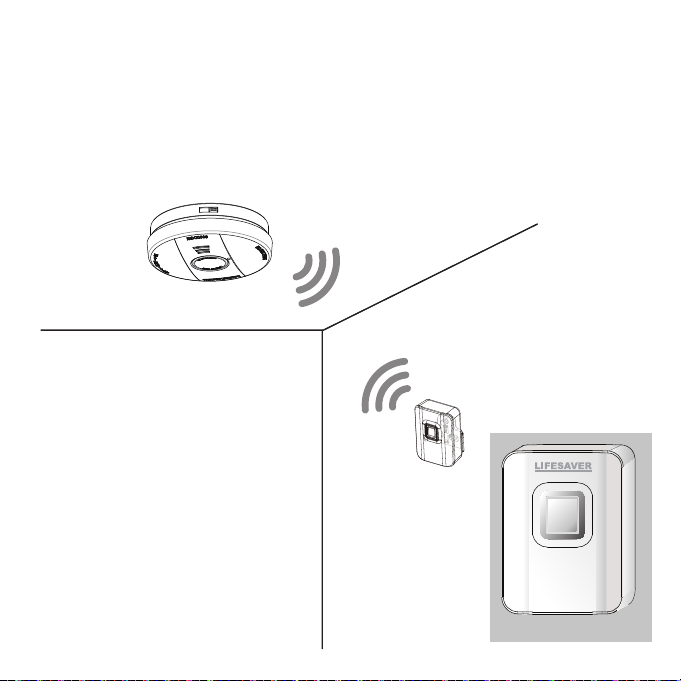
14. Smoke Alarm Controller
The LIFESAVER 6000 series smoke alarms can be wirelessly controlled with a Smoke Alarm Remote
Control Model 6000THL. The Remote Control can TEST, LOCATE and HUSH the smoke alarms. Smoke
Alarms Models 6000 and 6000RL require a wireless base (Model 6000WB) to enable this feature.
CEILING
WALL
6000DCW, 6000 and 6000RL smoke alarm,
6000WB wireless base.
Model 6000THL
Table of contents
Other PSA Smoke Alarm manuals

PSA
PSA Lifesaver LIF5000 User manual

PSA
PSA LIFESAVER LIF10YPEW User manual

PSA
PSA LIF5800/2 User manual

PSA
PSA LIFESAVER 5800RF User manual

PSA
PSA LIFESAVER LIF5800ACF User manual

PSA
PSA Homeguard HG2000 User manual

PSA
PSA LIFESAVER LIFPE9/1 User manual

PSA
PSA Lifesaver 6800RL User manual

PSA
PSA Lifesaver HA240 User manual

PSA
PSA LIFESAVER LIFPE10LP User manual


