PSA Lifesaver HA240 User manual
MODEL HA240
FIXED TEMPERATURE DESIGN HEAT ALARM
INSTALLATION AND USER MANUAL
IMPORTANT! READ ALL INSTRUCTIONS BEFORE INSTALLATION AND
SAVE THIS MANUAL FOR FUTURE REFERENCE.
WARNING! THIS HEAT ALARM IS NOT DESIGNED AS AN EARLY WARNING
TO A FIRE BECAUSE IT DOES NOT DETECT SMOKE.
SEE LIMITATIONS OF THE HEAT ALARM IN SECTION 12 FOR
DETAILS
WARNING! REMOVAL OF HEAT ALARM BATTERY AND DISCONNECTING
OR LOSS OF AC POWER WILL RENDER THIS UNIT INOPERA-
TIVE.
DO NOT TRY TO REPAIR THIS HEAT ALARM YOURSELF.
REFER TO INSTRUCTIONS IN SECTION 4 FOR MAINTENANCE.
CONTENTS
1. SPECIFICATIONS
2. RECOMMENDED LOCATIONS OF ALARMS
3. LOCATIONS TO AVOID
4. INSTALLATION INSTRUCTIONS
5. WIRING INSTRUCTIONS
6. MOUNTING INSTRUCTIONS
7. INSTALLING THE BASE PLATE
8. OPERATION
9. FALSE ALARMS
10. MAINTENANCE
11. CLEANING YOUR ALARM
12. LIMITATIONS OF HEAT ALARMS
13. GOOD SAFETY HABITS
14. WHAT TO DO WHEN THE ALARM SOUNDS
15. BCA REQUIRED PROTECTION
16. SERVICE AND WARRANTY
240Vac 50Hz, 80mA max, 9V long life battery back up, single and or multiple station (24 units maximum).
The heat alarm is designed to activate at 73°C when the temperature range is between 58°C and 88°C.
Temperature rating -------------------- 73°C (163.4°F) Fixed temperature only
Maximum ambient -------------------- 88°C (190.4°F) temperature at heat alarm
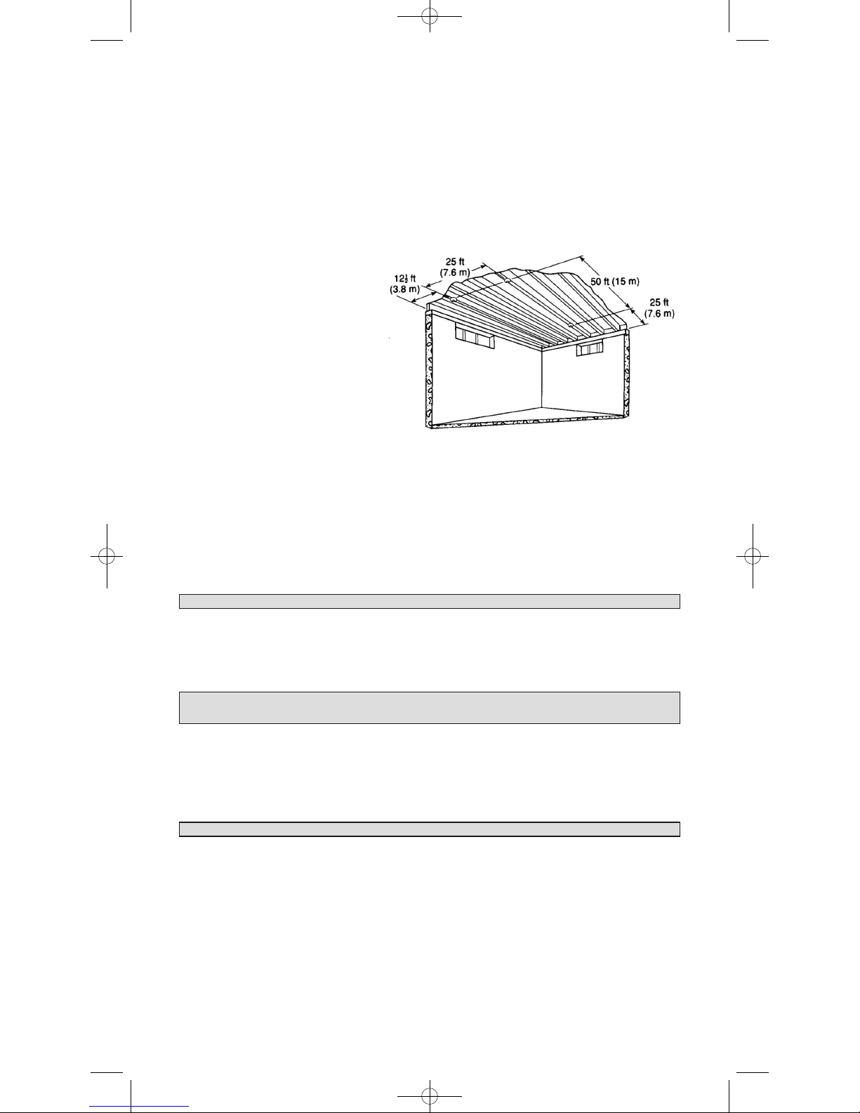
Recommended coverage ---------------- 230 square metres (Note “A”)
Recommended spacing -------------------15.3 metres
Maximum distance from wall ----------------- 7.6 metres (Note “B”)
Note A: Maximum coverage is based on providing equal response time as sprinkler devices spaced at 3.0 metre
intervals (9.4 square metres) on a smooth ceiling approximately 4.6 metres high.
Higher ceilings may adversely affect response time and earlier response time may be obtained by
reducing the spacing between alarms.
Note B: Maximum distance is from any wall or ceiling projection extending down more than 30cm.
ELECTRICAL RATING: 240Vac, 50Hz, 80mA max per alarm with 24 alarms interconnected.
Interconnect compatible with smoke alarms of Models LIFESAVER LIF5000, LIF5800, LIF5800RL and
Lifesaver Visual Signalling Device SL240 And LANSON 240I, Isolation Relay LIFRK10A/9.
1
1. SPECIFICATIONS
This Heat Alarm must only be wired to a 240Vac 50Hz sine wave current supply.
1004-7201-01(HA240)_V2:_ 2010.9.2 9:20 AM Page 1
2. RECOMMENDED LOCATIONS OF ALARMS
2.1: Heat alarms give an audible warning when the temperature at the alarm reaches 73°C. Heat alarms are ideal
for kitchens, garages, cellars, boiler rooms, attics and other areas where there are normally high levels of
fumes, smoke or dust which preclude the use of smoke alarms due to the risk of false alarms. For normalsized
bungalows, two-story houses, flats and maisonettes, the PSA recommends that the minimum level of protec-
tion should comprise smoke alarms in the hallways and staircases. This minimum standard necessitates one
smoke alarm in the hallway of a typical bungalow or one smoke alarm on each level of a two-story house.
Heat alarms should not be used in these circulation areas. If there are, for example, long hallways, even the
minimum standard may necessitate additional interconnected smoke alarms. If, however, the design of the
dwelling does not comply with modern fire safety standards, or if factors such as the presence of several
young children, elderly occupants or disabled people, or smokers, the use of portable heaters or solid fuel fires
during the night, or the use of electric blankets, particularly by the elderly, PSA advises that additional detec-
tion devices, installed within rooms, may be necessary.
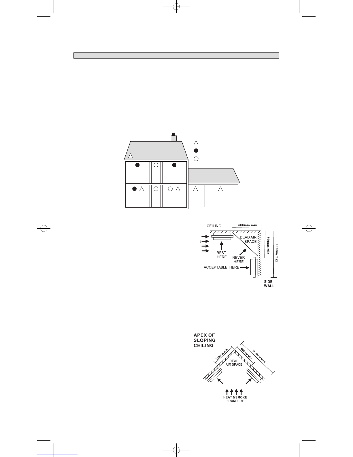
BEDROOM
ATTIC
BEDROOM
HEAT ALARM
IONISATION SMOKE ALARM
PHOTOELETRIC SMOKE ALARM
KITCHENLIVING ROOM GARAGE
UTILITY/
LAUNDRY
2.2: The most favourable mounting location for a Heat
Alarm is on the ceiling and in the centre of the room.
At this location, the alarm is closest to all areas
of the room.
EXCEPTION : When the mounting surface
might become considerably warmer or
cooler than the room, such as a poorly
insulated ceiling, below an unfinished attic,
or an exterior wall. In these cases the alarm
should be mounted on an inside wall.
2.1: If the alarm cannot be located in the centre
of the room, an off-centre location can be
used on the ceiling. When off-centre
mounting an alarm on the ceiling, locate it
at a minimum of 300mm from the side wall (see diagram A)
2.4: If a ceiling mounting location is not possible, the next logical location for mounting
Heat Alarm is on the side wall. When mounting the alarm on the wall, use an inside
wall with the top edge of the alarm at a minimum of 300mm and a maximum of
600mm below the ceiling. (see diagram A)
Diagram A
2.5: When mounting the alarm on a sloping
ceiling, it should not exceed 1500mm away
from the apex. The spacing of additional alarms, if
any, should be based on a horizontal distance
measurement, not a measurement along the slope
of the ceiling (see diagram“B”)
Areas for
Heat Alarms
Diagram B
1004-7201-01(HA240)_V2:_ 2010.9.2 9:20 AM Page 2
2
2.6: In rooms with open joists or beams,all
ceiling mounted alarms shall be located on the
bottom of such beams.
(See diagram “C”)
2.7: Alarms installed on an open-joist ceiling
shall have the smooth ceiling spacing reduced
to no more than half of the listed spacing
when measured at right angles to the solid
joist. (See diagram “C”).
MOBILE HOME INSTALLATION
Mobile homes built in the past five years have been designed to be energy efficient. Install Heat Alarms as previ-
ously outlined (refer to RECOMMENDED LOCATIONS and diagram A). In mobile homes that are not well insu-
lated compared to present standards, extreme heat or cold can be transferred from the outside to the inside through
poorly insulated walls and roof. This may create a thermal barrier which can prevent the heat from reaching an
alarm mounted on the ceiling. In such units, install the heat alarm on an inside wall with the top edge of the alarm at
a minimum of 300mm and a maximum of 600mm below the ceiling. (See diagram A).
If you are unsure about the installation in your mobile home, or if you notice that the outer walls and ceiling are ei-
ther hot or cold, install the alarm on an inside wall.
3. WARNING ! LOCATIONS TO AVOID
3.1 In front of air ducts used for heating and air conditioning, near ceiling fans, or other high air flow areas.
3.2 In an area where the temperature may fall below 5°C (41°F) or rise above 88°C (190.4°F).
3.3 Near fluorescent lights - electronic “noise” may cause nuisance alarms.
Diagram C
4. INSTALLATION INSTRUCTIONS :
“PLEASE READ CAREFULLY”
4.1 This Heat Alarm should be installed with an AS approved junction box. All connections must be
installed by a qualified electrician and be in accordance with the relevant requirements of the SAA
Wiring Rules AS3000 Standards and / or any other codes having jurisdiction in your area.
4.2 The appropriate power source is 240Vac 50Hz continuous single phase sine wave current supplied from a
non-switchable circuit which is not protected by a RCD.
4.3 This Heat Alarm must be mounted at a minimum height of 2 metres.
5. WIRING INSTRUCTIONS: FOR A.C. QUICK CONNECT HARNESS
5.1 For units that are used as single station, DO NOT CONNECT THE WHITE WIRE . Leave the
red wire insulating cap in place to make certain that the WHITE wire cannot contact any metal
parts.
5.2 When alarms are interconnected, all interconnected units must be powered from a single final sub
circuit.
5.3 A maximum of 24 devices may be interconnected only with smoke alarms of Models LIFESAVER
LIF5000, LIF5800, LIF5800RL, LANSD240I and Lifesaver Visual Signalling Strobe SL240.
CAUTION ! ISOLATE MAIN POWER TO THE CIRCUIT BEFORE WIRING THE
ALARM.
1004-7201-01(HA240)_V2:_ 2010.9.2 9:20 AM Page 3
3
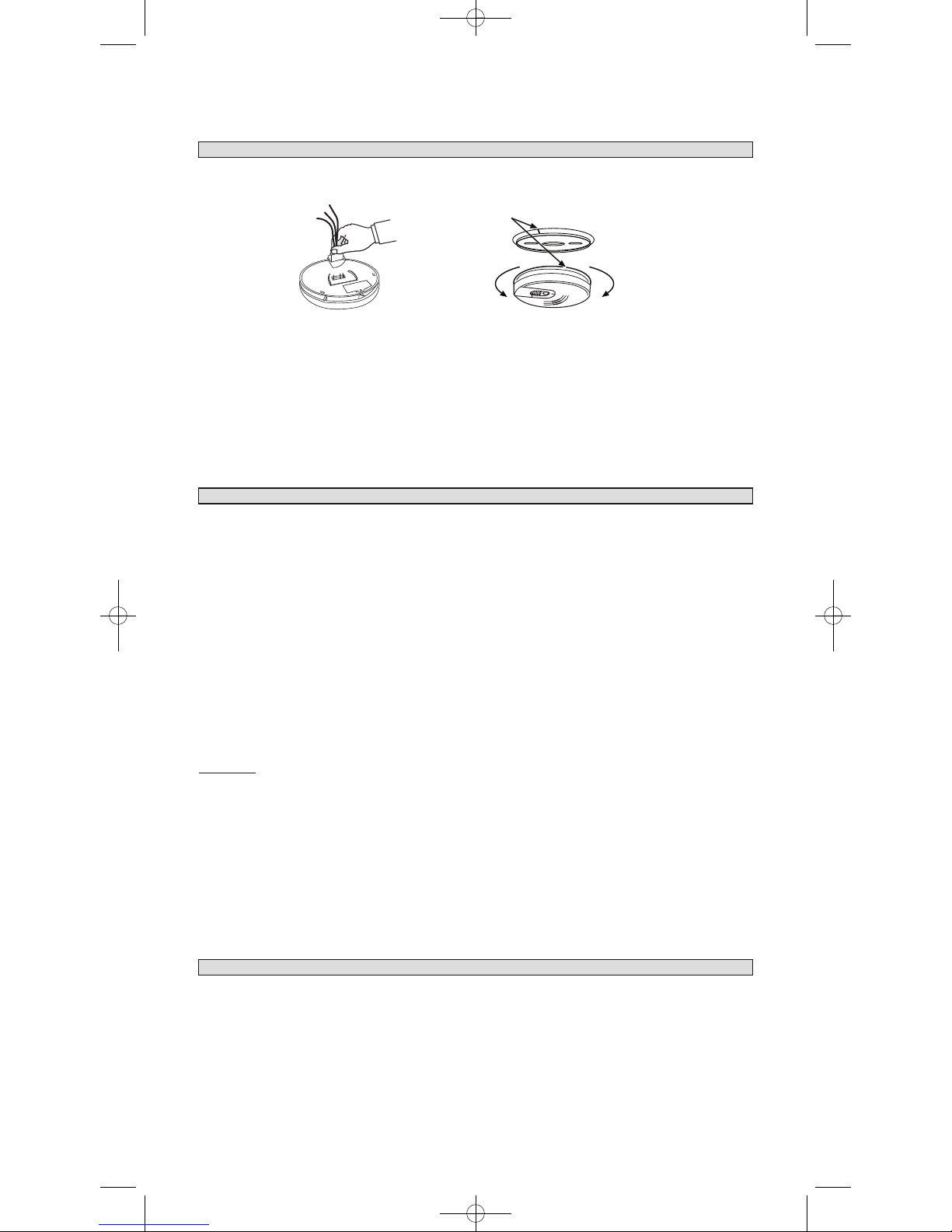
6. MOUNTING INSTRUCTIONS
A trim ring is provided on the back of the Heat Alarm. This trim ring is removed by holding the trim ring and twist-
ing the Heat Alarm in the direction indicated by the TURN TO REMOVE arrow. The trim ring is secured to the
heat alarm by a trim lever.
CAUTION ! THE COVER IS A SEALED UNIT AND HAS NO REMOVABLE
SERVICEABLE PARTS ! DO NOT TAMPER.
6.1 Secure a suitable junction box near the position of the Heat Alarm, ensure the quick connect cable length
is long enough to reach the junction box for termination to be made.
6.2 Connect Active, Neutral and Switch line to the Heat Alarm cable using the terminal connection block pro-
vided. Secure these terminals inside the junction box.
6.3 Punch out the suitable fixing holes on the trim ring and then pull the AC connector through the centre of
the trim ring.
6.4 Secure the trim ring to the ceiling using the fixing holes provided.Connect the 9V battery (back up) into
the battery compartment. Now, plug in the AC connector into the back of the Heat Alarm. Ensure the
locks on the AC connector snaps firmly into place.
6.5 Now mount the heat alarm onto the trim ring. Rotate the heat alarm until the heat alarm snap firmly into
place.
NOTE:PLEASE ENSURE THAT BATTERY IS INSTALLED PRIOR TO MOUNTING OF HEAT ALARM
Switch on the A.C. power and the green A.C. power ‘ON’ indicator should be lit. The Heat Alarm is now operating
on mains power.
A
N
FUSE OR CIRCUIT BREAKER
RED
WHITE
BLACK
ASW
N
RED
WHITE
BLACK
ASW
N
RED
WHITE
BLACK
ASW
N
RED
WHITE
BLACK
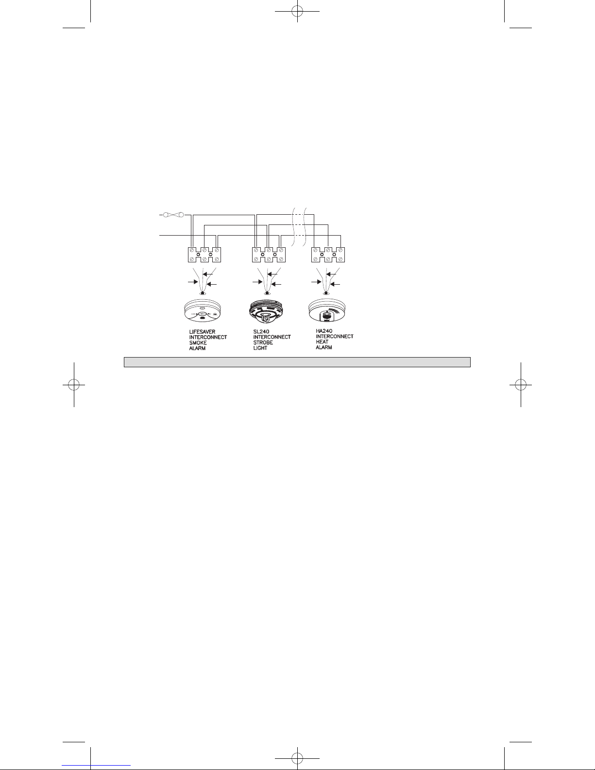
5.4 The maximum wire run distance between the first and last unit in an interconnected system is 307 metres.
Figure 1 illustrates interconnection wiring. Improper connection will result in damage to the alarm, failure
to operate, or electrical shock hazard.
5.6 Make certain alarms are wired to a continuous (non-switched) final sub-circuit.
Note: Use approved listed Australian Standards cable 1.0mm² TPS or larger as
required by local codes.
FIGURE 1 “INTERCONNECT WIRING DIAGRAM”
ALARM HARNESS --------------------CONNECTED TO:
BLACK -------------------------------N
WHITE -------------------------------SW
RED -------------------------------A
FIGURE 1: TYPICAL DIAGRAM SHOWING INTERCONNECTION OPTIONS
1004-7201-01(HA240)_V2:_ 2010.9.2 9:20 AM Page 4
4
7. INSTALLING THE BASE PLATE
After installation TEST your alarm by pressing and holding the test button for several seconds. You can also use a
hand held hair dryer to test your heat alarm.
Complete details on this procedure are outlined in Section 8.
CAUTION ! Early warning fire detection is best achieved by the installation of smoke alarms in all rooms and areas
of the household as follows: A smoke alarm should be installed in each separate sleeping area (in the
vicinity of - but outside the bedroom) and heat or smoke alarm where appropriate in the living rooms,
dining rooms, kitchens, hallways, attics, furnace rooms, closets, utility storage rooms, basements, and
attached garages.
8. OPERATION
The Heat Alarm is operating once A.C. power is applied, new battery is installed and testing is complete. When
the Heat Alarm senses temperatures above 73°C (163.4°F) (plus or minus a few degrees), the horn will sound a loud
(85db) pulsating alarm until the temperature drops below 73°C (163.4°F). The heat alarm is designed to activate at
73°C when the temperature range is between 58°C(136.4°F) and 88°C(190.4°F).
FLASHING RED LED LIGHT: This Heat Alarm is equipped with a flashing Red LED. The LED is located under
the test button and has two functions.
1. Stand-by Condition---The Red LED will flash every 30-40 seconds to indicate that the Heat Alarm is operating
properly.
2. Alarm Condition ----When the unit detects heat and goes into alarm the red LED will flash rapidly ( 2-3
times per second ). The rapid flashing LED and pulsating alarm will continue until the
temperature drops below 73°C (163.4°F).
WHEN HEAT ALARMS ARE INTERCONNECTED with compatible Smoke Alarms, only the Red LED of the
originating unit will flash rapidly. All other units in the interconnect system will sound an alarm but their Red LED’s
will not flash.
TESTING: Test by pushing the test button on the cover and hold it down for a minimum of 5 seconds. This will
sound the alarm if all the electronic circuitry and horn are working correctly.
The test switch may not cause a test signal if the ambient temperature is below 8° C (20°F). In this
case, test the unit by blowing hot air at the alarm sensing element with a hair dryer held about
20cm from the unit.
If no alarm sounds, check the fuse or circuit breaker supplying power to the alarm circuit, if the alarm still does not
sound the unit may have defective battery or other failure.
IT IS RECOMMENDED TO TEST THE ALARM WEEKLY TO ENSURE PROPER OPERATION.
Erratic or low sound coming from your alarm may indicate a defective alarm, and it should be returned for service.
(SEE SECTION 16)
CONNECTOR
SQUEEZE
LOCKING
ARMS AND PULL
FIGURE. 3 FIGURE. 4
INSTALL
MARKS
REMOVE
FIGUE 5
TAMPER RESIST
LOCKING PIN
9. FALSE ALARMS
To avoid false alarms, DO NOT USE WHERE THE MAXIMUM ROOM TEMPERATURE WILL EXCEED 88°C .
Heat Alarms respond only to heat. They do not detect smoke. If the alarm does sound, check for fires first. If a fire is
discovered, get out of the house and call the Fire Brigade. If no fire is present, check to see if one of the reasons
listed in Section 2 may have caused the alarm.
1004-7201-01(HA240)_V2:_ 2010.9.2 9:20 AM Page 5
Table of contents
Other PSA Smoke Alarm manuals

PSA
PSA LIFESAVER LIFPE9/1 User manual

PSA
PSA LIFESAVER LIF5800ACF User manual

PSA
PSA LIF5800/2 User manual

PSA
PSA LIFESAVER LIFWMB2 User manual

PSA
PSA LIFESAVER 5800RF User manual

PSA
PSA LIFESAVER LIFPE10LP User manual

PSA
PSA Lifesaver LIF5000 User manual

PSA
PSA LIFESAVER 6000DCW User manual

PSA
PSA Homeguard HG2000 User manual

PSA
PSA Lifesaver 6800RL User manual


