manuals.online logo
Brands
  1. Home
  2. •
  3. Brands
  4. •
  5. Pyronix
  6. •
  7. Security System
  8. •
  9. Pyronix PCX 256 User manual

Pyronix PCX 256 User manual

RINS987-2
Quick Reference Guide
If a device connected to the PCX is not installed correctly or
lost communication with the panel, “DEVICE FAIL” will be
shown on the LCD keypad followed by a 3-figure device code.
The first digit identifies each type of device:
The digits after refer to that devices address, for example:
DEVICE FAIL 401 = Means that the Remote Input Expander
addressed as 01 has a problem. Check the connections
DEVICE FAIL 202 = Means that the LCD keypad addressed
as 02 has a problem. Check the connections.
DIGI COM FAIL 100: Call to ARC failed. Check all ARC call
details and signalling formats.
MODEM FAULT: System unable to communicate with digi
modem card. Check that it is installed properly (power
system down before removing it/installing it).
Entering The Engineers Menu
Exiting The Engineers Menu
Engineers mode can only be entered if all partitions
are disarmed.
Enter your Engineers code (default 9999)
Any faults will be shown.
Press m
‘ARM/DISARM THE SYSTEM’ will be displayed.
Press m
‘FORCE ARM ON 1st INPUT[01]’ will be displayed
(can be used to quick arm the system. Press m
The keypad will start
beeping, and ‘Enter Code’
will be displayed.
Enter your engineers code again.
‘INHIBIT FIRE/HU’ will be shown
!!
D
C
B
A
ENTER CODE
[ ]
!!
D
C
B
A
Active Faults
BatteryFault100
In Engineers Mode, press m, until you reach a main menu
item (i.e. in capital letters).
Press ¤
!!
D
C
B
A
Please Wait
Saving NVM Data
1 = End Station
2 = Keypad
3 = Tag Reader / Door Station / RIX2
4 = Remote Input Expander
5 = Remote Output Expander
LINE FAULT: Line fault signalled by digi modem card,
check voltage across A and B terminals (50V). Check line
dials out OK with a normal telephone.
ERROR INPUT PARTITION NOT ACCESSIBLE: An input
has been programmed to a partition for which no arming
point is valid to disarm.
ENGINEER MODE ACCESS DENIED: Means that a
partition is armed on the system or a fault hasn’t been
cleared. Make sure you clear the fault or disarm the
partition on the corresponding keypad.
Fault Indictions
Fault IndictionsDevice Codes
Pyronix Limited
Pyronix House
Braithwell Way
Hellaby
Rotherham
S66 8QY
UK
Customer Support Line (UK only): 0870 122 3360
This is a national rate line
Hours of business: 7.00am - 7.30pm
E-mail: customer[email protected]
website: www.pyronix.com
Fault Analysis
Engineer Test Functions
Engineer Tests
Popular PGM Types
Diagnostics
Input Types
In the Engineers Menu, Press m until you reach
‘DIAGNOSTICS’. Press l key.
‘View PSU’s’ will be displayed.
This displays the voltages and
current for the Endstation,
RIXs, ROXs, Keypads and
Readers. Press l if you wish to view this, or press
m for the next option.
‘View Inputs’ will be displayed.
This displays the resistence values for each input on the
Endstation, RIXs, Keypads and Readers.
Press l if you wish to view this:
‘Endstation Inputs’ will be
displayed, press l key.
“cccccccc” should be
displayed if all inputs are
closed. (c = closed. o = open. F = fault (input not reading
correctly))
Press l again to view the
resistance reading of each
input.
Press m to scroll to RIX, Keypad, or Reader inputs.
‘Calibration’ will be displayed. Press m.
You will be returned to Engineers Menu.
In the Engineers Menu, Press m until you reach
‘ENGINEER TESTS’. Press l. Select a sound using the
© key to play when a test has been accepted. Press l.
‘Walk Test’ will be displayed. Press l and select the
partitions to be walk tested. Press l. The inputs will be
displayed until they have been walk tested,‘Walk Test
Complete’ will be shown once all completed. Press l.
‘Test Control’ will be displayed, this can be used to soak
test inputs for a number of days. Press l for this function
or m for thenext option.
‘Test Bell’ will be displayed. This will test both the strobe
and bell outputs. Press l for this or m for the next option.
‘Battery Load Test’ will be displayed. To perform a battery
load test press l or m for the next option.
‘Test PGM’s’ will test any PGM output on the system. This
can be used for testing signals to the central station (both
the ATE pins and Digi channels are programmed from
PGM outputs).Press l.
Enter the PGM number you would like to test (see below)
or use the {and }arrow keys to scroll through them.
Press l to test that output. Press m to cancel.Press m.
You will be returned to Engineers Menu.
!!
D
C
B
A
Input [001] [1]
04.7k CC
!!
D
C
B
A
cccoooFF
!!
D
C
B
A
Endstation PSU
13.7V 0.20A
0000
0001
0002
0003
0004
0005
0006
0007
0008
0009
0014
0016
0017
0018
Unused
Fire
Hold Up Any
Intruder Any
Final Arm All
Abort
Confirmed Any
Tamper Any
Duress
HU Device Any
Bell Any
Strobe Any
Omit Rearm Any
Unconfirmed Any
Final Arm Any
Keyswitch Disarm
Entry/Exit
Follow Input
Viper Reset
PIR Latch
Line Fault
AC Fail
Battery Fualts
Global Fault 1 (armed)
Global Fault 2 (any)
Test ATE/GSM
Test ATS
Follow inputs
0022
0025
0033
0035
0037
0039
0051
0052
0053
0055
0056
0063
0064
1000-
1256
00
01
02
03
04
05
06
07
08
09
10
Unused
Fire
Gas
HU
Silent HU
Tamper
Immediate
Entry/Exit (EE)
Access (A)
A (Part EE)
EE (Part A)
PTS
Switcher
24 Hour
Sub Part Control
Fault
Closure Supervision
Shunt Input
Disarm Input
Keyswitch Latched
Entry Shock Input
Keyswitch Pulsed
11
12
13
15
16
17
18
19
20
21
23
Resistance Values
The system diagnostics that can be displayed are: Input
resistance, system voltages and current.
The Engineer Test function allows you to walk test and soak
test inputs, toggle PGM outputs, do a battery load test and
signal communication tests.
Alarm = 4k7
Tamper = 4k7
Mask = 6k8
TS50131-3:2003
EN50131-1
PD6662
Security Grade 3
Environmental Class 2
3
RINS987-2
Changing Inputs
Installing Keypads/Readers
Installing RIXs (Input Expanders)
Installing ROXs (Output Expanders)
Programming Tags Miscellaneous
Changing Outputs The Engineer/Anti-Code Reset
!!
D
C
B
A
Input Name
Input 001
!!
D
C
B
A
Arm Point Arms
[ AB ]
!!
D
C
B
A
Arm Point In
[ A ]
!!
D
C
B
A
Arm Point Name?
!!
D
C
B
A
KEYPAD CODE?
[ ]
!!
D
C
B
A
Input [001]
Input 001
!!
D
C
B
A
Type
Keypad [0]
!!
D
C
B
A
ATE Pin 1[0001]
Fire
In the Engineers Menu, Press m until you reach
‘CHANGE INPUTS’. Press l.
Select the input you would like
to program and press l.
Choose the input type (see
‘input types’ table overleaf)
Select the partition you wish the input to be programmed into.
Enter ‘Any’ or ‘All’ (individual partition or common partition)
‘Input Attributes’ will be displayed. Here you can choose
from several options: Chime, Omittable, Double Knock,
Normally open, Confirm group etc. Press ©to switch
between the different options. Press l for the next option.
‘Input Name’ will be displayed.
Press l,the input name will
be displayed, you may alter this
using the relevant keys for the letters. Once done press l,
and do the same for the rest of the inputs.
Press m to go back to the Engineers menu.
In the Engineers Menu, Press m until you reach
‘ASSIGN KEYPADS/READERS?’. Press l.
Select the address of the keypad/reader you have installed.
Enter the type:
0 = Keypad
1 = Reader
2 = Not Used
(This example shows a keypad) Press l.
‘Arm Point Arms’ will be
displayed, choose which
partitions you would like the
keypad to arm/disarm. Press l.
‘Arm Point Disarms’ will be displayed, choose which
partitions you would like the keypad to arm/disarm. Press l.
‘Arm Point In’ will be
displayed, choose which
partition you would
like the keypad to operate
in. Press l.
‘Arm Point Name’ will be
displayed, if you wish to enter
a name for the arm point
press l.
Press m twice to go back to the Engineers menu.
Also you will need to address
each keypad individually.
To do this, in day mode, keep
hold of the © key until
‘KEYPAD CODE’ is displayed.
Release the © key and enter ‘2000’. press l.
‘Address’ will be displayed, enter the relevant address for
the keypad and press l. For other options press l, or
press ¤to save the data.
The Input numbers for each keypad are as follows:
In the Engineers Menu, Press m until you reach
‘CHANGE OUTPUTS’. Press l.
‘Endstation PGMs’ - this allows you to change the onboard
PGMs (PGM1, PGM2, PGM4 or PGM5) and also the ATE
outputs for the communication loom.
Press lEnter the required PGM type (see the table
overleaf) or press © to scroll
through. Press lto go to the
next PGM/ATE number.
Press m once finished.
‘RIX PGMs’ will be displayed, Press lif required and
enter the relevant address of the RIX you wish to program.
Press l and the PGMs may be changed.
Press m once finished.
‘ROX Module PGMs’ will be displayed, here you may
install any PCX-ROXs. Press lif required and enter
the relevant address of the ROX you wish to install.
‘ROX Installed’ will be shown, press © to select ‘YES’ and
Press l - you can now change the relevant PGMs.
Press m once finished.
Do the same for Keypad and Reader PGMs. Press m
once finished, you will be returned to the engineer menu.
In the Engineers Menu, Press m until you reach
‘CHANGE OUTPUTS’. Press l.
Press m until you reach ‘ROX Module PGMs’, here you
may enable any PCX-ROXs you have installed. Press l
‘ROX Address?’ will be displayed, enter the address
of the RIXs you have installed. Press l.
‘ROX Installed?’ will be displayed press © to toggle
between YES and NO. Press l
Press m until you return to the Engineer Menu.
After an alarm activation, a
valid user code may be
entered, this will silence the
alarm. The display will show
‘Alarm Silenced’ on the top line, on the bottom line the
display will show and the activation that has just occurred.
Press l.
The time and date will be displayed and the Power LED will
flash indicating that a restore is required. Enter your
engineering code: “All faults have been cleared” will be
displayed Press l.
After an alarm activation, a
valid user code may be
entered, this will silence the
alarm. The display will show
‘Alarm Silenced’ on the top line, on the bottom line the
display will show the restore number. For Example:
‘Restore G12298’. Press l.
The time and date will be displayed and the Power LED will
flash indicating that a restore is required. Enter the anti-
code reset number, ‘Engineer Restore Performed’ will be
displayed. Press l.
In the Engineers Menu, Press m until you reach ‘INSTALL
RIX?’. Press l.
‘RIX Address?’ will be displayed, enter the address of the
RIX you have installed. Press l.
‘RIX Installed?’ will be displayed press © to toggle
between YES and NO. Press l, you will be returned
to the Engineer Menu.
In day mode, press © and enter the master manager
code (default 5678). Press muntil you reach ‘CHANGE
CODES’. Press l.
‘Change User Codes’ will be displayed. Press l.
Enter the user number you wish the tag to be
programmed on. Press l.
‘Enter User Code’ will be displayed. If there are asterisks
in the brackets then a code has already been entered.
Either delete the code (by pressing §) or press mand
select another user number.
Once the brackets are empty,
hold up a PCX-TAG to LCD
keypad (shown right). The
keypad will be beep if the tag
has been accepted. Press l.
Select the relevant options for the user (to go to the next
option press l). One option that may need to be changed
is ‘Flexi Arm’ - if set to ‘YES’ then you can select which
partitions you would like to arm, or to automatically arm
the partitions when you put a fob up to the keypad set this
option to ‘NO’.
User Level Arm: This function allows the system to
operate as a “Level Arm” (YES) or “Partition” (NO) system.
Common Exit Mode: If set to ‘YES’ this option will
automatically arm the partition on the ‘highest priority’ exit
mode. (Final Exit and PTS are higher than timed exit)
2 Key HU: Keys 1 and 7 pressed together perform a Hold
Up activation. These will need to be enabled in this option.
Flexi-Unset: If set to ‘YES’ you will be required to disarm
each partition manually. Or if set to ‘NO’ the system will
disarm all partitions the code/keypad are assigned to.
Sign On Message: Allows you to add your own company
name on start up (Default PCX 256)
The system can be programmed so that it can be only fully
reset by an engineer or by an anti-code reset. This can be
programmed in “Engineer Reset Options”.
The log stores up to 3000 events. To operate the log
use {and } the and keys to scroll through each event,
to view more information (such as user and input numbers)
press the §key.
By default, all inputs are pre-set as ‘unused’ so you will need to
program each individual input you require. The input will not be
‘live’ until you have exited the engineers menu.
The keypad has an inbuilt tag reader and can be used to
arm/disarm the system without entering a user code.
To program tags into the system you must be in the master
manager menu (NOT the Engineers menu).
Other notable Engineer functions::
This function allows you to enable any keypads or proximity
readers you have installed on the system. You must exit
the Engineers menu in order for the changes to take affect.
241-242
243-244
245-246
247-248
249-250
251-252
253-254
255-256
Input Number
LCD Keypad 00
LCD Keypad 01
LCD Keypad 02
LCD Keypad 03
LCD Keypad 04
LCD Keypad 05
LCD Keypad 06
LCD Keypad 07
Address
!!
D
C
B
A
Enter User Code
[******]
Tag
,/+.
JKL
ABC
MNO
DEF
PQRS
GHI
TUV
WXYZ SPACE
Site Options
Performing an Engineer Reset
Performing an Anti Code Reset
System Displays
Engineer Reset Options
Review Logs
This function allows you to enable Engineer Reset for
different alarm types such as Intruder, Hold Up, Confirmed
etc. Also allows you to enable an Anti-Code reset.
!!
D
C
B
A
Alarm Silenced
Restore Required
!!
D
C
B
A
Alarm Silenced
Restore G12298

Other manuals for PCX 256

4

Other Pyronix Security System manuals

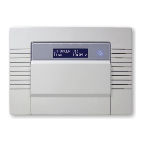
Pyronix ENFORCER V11 Operating instructions

Pyronix

Pyronix ENFORCER V11 Operating instructions

Pyronix PCX 256 User manual

Pyronix

Pyronix PCX 256 User manual

Pyronix PCX-12 User manual

Pyronix

Pyronix PCX-12 User manual

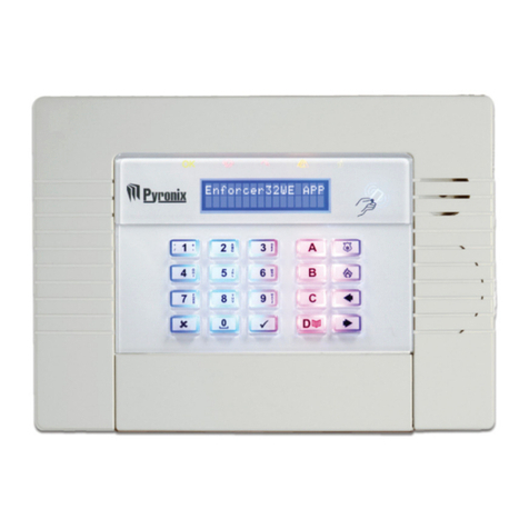
Pyronix Enforcer 32WE User manual

Pyronix

Pyronix Enforcer 32WE User manual

Pyronix PCX 46 User manual

Pyronix

Pyronix PCX 46 User manual

Pyronix ENFORCER RINS1706-1 Service manual

Pyronix

Pyronix ENFORCER RINS1706-1 Service manual

Pyronix ENFORCER Series Owner's manual

Pyronix

Pyronix ENFORCER Series Owner's manual

Pyronix PCX 46 User manual

Pyronix

Pyronix PCX 46 User manual

Pyronix ENFORCER V11 Service manual

Pyronix

Pyronix ENFORCER V11 Service manual

Pyronix Enforcer 32WE User manual

Pyronix

Pyronix Enforcer 32WE User manual

Pyronix PARAGON E User manual

Pyronix

Pyronix PARAGON E User manual

Pyronix Enforcer 64 User manual

Pyronix

Pyronix Enforcer 64 User manual

Pyronix Matrix 424 User manual

Pyronix

Pyronix Matrix 424 User manual

Pyronix Enforcer 32WE User manual

Pyronix

Pyronix Enforcer 32WE User manual

Pyronix OCTAGON II User manual

Pyronix

Pyronix OCTAGON II User manual

Pyronix V2 TEL User manual

Pyronix

Pyronix V2 TEL User manual

Pyronix PCX 256 Owner's manual

Pyronix

Pyronix PCX 256 Owner's manual

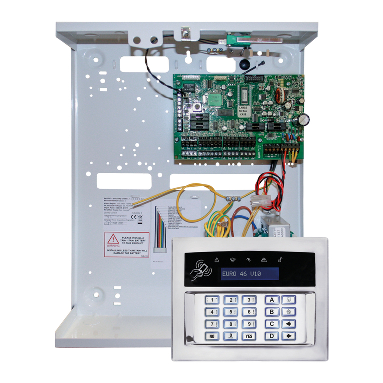
Pyronix EURO 46 V10 User manual

Pyronix

Pyronix EURO 46 V10 User manual

Pyronix Vocaliser User manual

Pyronix

Pyronix Vocaliser User manual

Pyronix Enforcer User manual

Pyronix

Pyronix Enforcer User manual

Pyronix RINS1902-2 User manual

Pyronix

Pyronix RINS1902-2 User manual

Pyronix Enforcer 32-W User manual

Pyronix

Pyronix Enforcer 32-W User manual

Pyronix Enforcer User manual

Pyronix

Pyronix Enforcer User manual

Pyronix Matrix 6/816 User manual

Pyronix

Pyronix Matrix 6/816 User manual

Popular Security System manuals by other brands

EMC Security Connect+ installation instructions

EMC Security

EMC Security Connect+ installation instructions

AccessPRO Industrial XB275H07K Technical instructions

AccessPRO

AccessPRO Industrial XB275H07K Technical instructions

LONEALERT Man Down X Instruction guide

LONEALERT

LONEALERT Man Down X Instruction guide

GE Interlogix 60-875 Simon installation instructions

GE

GE Interlogix 60-875 Simon installation instructions

Indexa GA90-230 operating instructions

Indexa

Indexa GA90-230 operating instructions

Honeywell DIY Smart Home instructions

Honeywell

Honeywell DIY Smart Home instructions

Rosco SAFE-T-SCOPE STSK5465 Installation & user manual

Rosco

Rosco SAFE-T-SCOPE STSK5465 Installation & user manual

LWA SoS Work Instruction

LWA

LWA SoS Work Instruction

DAITEM Espace range user guide

DAITEM

DAITEM Espace range user guide

VSAIL VB-6617S Installation and operation manual

VSAIL

VSAIL VB-6617S Installation and operation manual

Ampac EvacUwiz MAN3084-0 Programming manual

Ampac

Ampac EvacUwiz MAN3084-0 Programming manual

Eaton i-on Series Administration and User Manual

Eaton

Eaton i-on Series Administration and User Manual

Sony Smarter Security Product guide

Sony

Sony Smarter Security Product guide

BT UC-351GP/E-UK Installation, maintenance and operation manual

BT

BT UC-351GP/E-UK Installation, maintenance and operation manual

Alpha Asenal EXPRESS E3 operating manual

Alpha Asenal

Alpha Asenal EXPRESS E3 operating manual

ZIGBEE 206 quick start guide

ZIGBEE

ZIGBEE 206 quick start guide

urmet domus 1068 user manual

urmet domus

urmet domus 1068 user manual

Sonel MPU-1 operating manual

Sonel

Sonel MPU-1 operating manual

manuals.online logo
manuals.online logoBrands
  • About & Mission
  • Contact us
  • Privacy Policy
  • Terms and Conditions

Copyright 2025 Manuals.Online. All Rights Reserved.