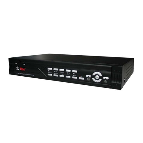
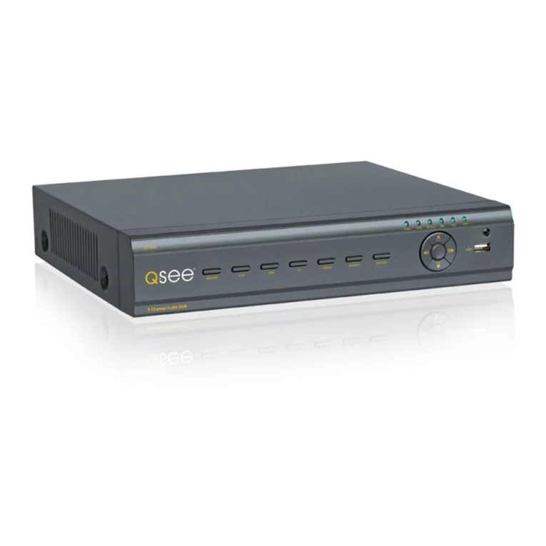
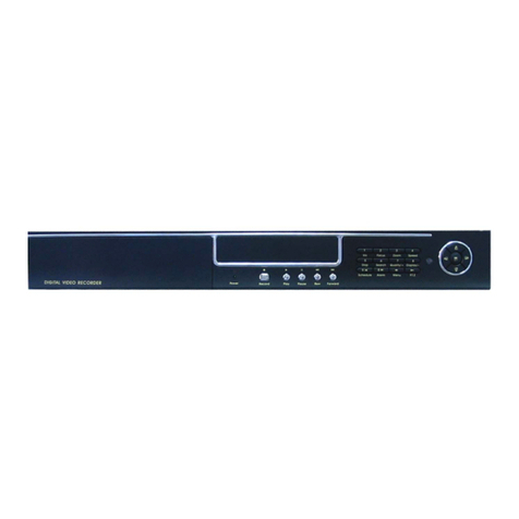
Q-See QSNDVR4R User manual

DVR
Model QSNDVR4R
4-channel Digital Video Recorder
With Networking capability
M
Ma
an
nu
ua
al
l

4 Channel Digital Video Recorder
Security Notice
zPower supply
This Digital-Video-Recorder applies DC 12 voltage indoor power supply. The voltage of the
power must be verified before using.
When the machine is not in use for a long time, pull out the plug from the socket and
disconnect the power.
zSecurity
This machine is indoor using equipment; in order to avoid dangers of short circuit or electric
shock, please do not expose the machine in rain or moist environment. In case any solid or
liquids get into the machine’s case, please cut off the power supply immediately, and ask for
qualified technicians to check the machine before restart.
This machine is precise instrument; do not attempt to repair any unit of the machine by
yourself without technical aids. When there is any malfunction with the machine, please ask
for qualified technicians to examine and repair, or contact the dealers in your area.
zInstallation
Please choose appropriate site to install the machine, to ensure well ventilation around the
machine to avoid the machine excessively hot. The machine cannot be installed near radiator
and ventilating trunk etc. heat sources, or under straight sunshine, or dusty places or anywhere
there is a chance for mechanical librations or impact.
zAdvice
While recording TV programs or VCD programs, please don’t pirate the third-party’s authority
and/or any other relative rights.
Features of this DVR
zVideo input: 4channels; video output: 2 channels.
zAudio input: 4channels; audio output: 1 channels.
zFour optional levels of image quality: very high, high, normal, low. Record and playback
frame rate change enable for recording.
zCompression mode: Modified MJEPG.
zCompatible with NTSC and PAL format.
zSupport alarm recording and time recording.
zMulti-function searches: be able to distinguish different alarm records and time records from
ordinary records; be able to search by time, by segment or by event.
zSupport various playback modes: pause, several fast forward and backward play modes.
zSupport zoom, auto, and PIP function.
z4 alarm input and 1 relay alarm output.
zEquipped with remote device
zSupport loss and motion detection functions.
zSupport watermark security protect.
zTriplex operation, may play back and search while it is recording. Both live and playback
pictures can be displayed on screen simultaneously.
zTotally independent from PC platform, thoroughly keeping away from shutdown caused by
inappreciative operations, complicated management and operation, and virus infection.
1

4 Channel Digital Video Recorder
Table of Contents
SYSTEM SETUP .....................................................................4
1. SETUP METHODS OF MENU .............................................................................................................4
2.ACCESS MENU................................................................................................................................4
3. SYSTEM SETUP ...............................................................................................................................5
4. TIME/DATE SET ..............................................................................................................................5
5. HDD FORMAT SET..........................................................................................................................6
6. FACTORY RESET..............................................................................................................................7
7. VIDEO SETUP..................................................................................................................................7
8. NAME SETUP ..................................................................................................................................7
9. BRI/CON SETUP ..............................................................................................................................8
10. RECORD SETUP.............................................................................................................................9
11. NETWORK SETUP..........................................................................................................................9
12. N/WENABLE SET.......................................................................................................................10
13. MAC SET.....................................................................................................................................11
14.ALARM SETUP ............................................................................................................................11
15. MOTION DETECTION SETTINGS...................................................................................................12
16.AREA SET....................................................................................................................................13
17. SCHEDULE SET ...........................................................................................................................13
18. PROTOCOL SET ...........................................................................................................................14
BUTTONS ON THE FRONT PANEL.............................15
1.RECORDING/PLAYING CONTROL BUTTONS AREA .........................................................................16
2.FUNCTION CONTROLAREA ...........................................................................................................17
3.CHANNEL CHOOSING CONTROLAREA ..........................................................................................18
DISPLAY STATUSES WHILE RUNNING....................19
1.SCREEN DISPLAY WHILE RUNNING...............................................................................................19
2.SCREEN DISPLAY WHILE PLAYING ................................................................................................19
3.TRIPDISPLAY ...............................................................................................................................20
SYSTEM CONNECTION...................................................21
1.BACK PANELAND CONNECTION TERMINALS ................................................................................21
2.VIDEO AND AUDIO CONNECTION ..................................................................................................22
3.ALARM CONNECTION....................................................................................................................22
4.HARD DISK CONNECTION..............................................................................................................24
USER GUIDELINE...............................................................25
1.START THE MACHINE.....................................................................................................................25
2

4 Channel Digital Video Recorder
2.TURN OFF THE MACHINE...............................................................................................................25
3.NORMAL RECORDING....................................................................................................................25
4.ALARM RECORDING......................................................................................................................26
5.TIME RECORDING..........................................................................................................................27
6.PLAYBACK.....................................................................................................................................27
7.SEARCH PLAY................................................................................................................................27
8. TIME SEARCH ...............................................................................................................................28
9. EVENT SEARCH.............................................................................................................................29
10. START STOP SEARCH...................................................................................................................29
11.ZOOM OPERATION .......................................................................................................................30
12.PIPOPERATION............................................................................................................................31
13.INFORMATION DISPLAY ...............................................................................................................31
14.DEFAULT SETTING.......................................................................................................................32
15.REMOTE CONTROL......................................................................................................................34
16.SERIAL PORT CONTROL...............................................................................................................34
17. PC VIEW SOFTWARE OPERATION................................................................................................35
EXTERIOR SIZE..................................................................41
INCASE LIST.........................................................................41
APPENDIX A: TROUBLE SHOOTING GUIDE ...............42
APPENDIX B: SERIAL PORT PROTOCOL .....................44
APPENDIX C: RECORD TIME ..........................................46
3

4 Channel Digital Video Recorder
S
Sy
ys
st
te
em
m
S
Se
et
tu
up
p
Before using the video recorder, the first step is to set up the system according to user’s needs;
otherwise the machine will run with the default settings.
1. Setup Methods of menu
When in setup mode, push upward button or downward button, the cursor will move among
the settable items, continuous pushing will make the cursor move among the options one by one,
and it can recur. The selected one will display in yellow color.
While choosing digital fields, e.g. year, month, day, hour, minute, second etc, push leftward
button or rightward button, the cursor can move leftward or rightward among the several digits of
one field, continuous pushing will make it move among digits one by one, and it can recur.
Please push “+” or “-” button to change the value that the cursor stands, push ENTER button
to enter sub menu and push menu button to return to previous menu.
2. Access Menu
System setup is achieved through entering menu, and then setting up on each option’s window.
To access the menu, please push menu button on the front panel, it will display password input
window.
The password is a random combination of 4 digits of “0-9”. The default is “0000”. To enter
the menu below, you have to input the correct password by pushing the digital buttons. If the
password you input is incorrect, the system will automatically return. If you don’t want to input
the password but give up the operation, you can push menu button to return. While inputting the
password, in order to avoid being revealed to stander-bys, the password you input is displayed on
the screen as “*” signs.
To change the password, please refer to “password change”.
4

4 Channel Digital Video Recorder
3. System Setup
When the cursor moves to System Setup, please push enter button, the System Setup window
will appear, which is illustrated as below.
PLAY REPEAT: if you set this to “YES”, when play the video to the end of the HDD, it will
automatically play the video from the beginning of the HDD again. If set to ‘NO’, it will stop
when play to the end.
VIDEO SOURCE: video format, NTSC/PAL
BUZZER SOUND: buzzer switcher, if set to “OFF”, the buzzer will not work..
4. Time/Date Set
When the cursor moves to System Setup, please push enter button, the System Setup window
will appear, which is illustrated as below. If the DVR is in recording mode you cannot access to
this menu unless you stop record first.
5

4 Channel Digital Video Recorder
.
Please push up, down, left, and right buttons to move the cursor, push add and DEC button to
modify the value.
FORMAT: the time display format, different for USA, EURO and Asia users.
DISPLAY: if set to “OFF”, time will not display no the screen.
LOCAL: time display position.
5. HDD Format Set
When the cursor moves to HDD FORMAT SET, please push enter button, the System Setup
window will appear, which is illustrated as below.
If you select “YES” and push the enter button, all video on the HDD will loss, if you want to
give up, please select “NO”.
6

4 Channel Digital Video Recorder
6. Factory Reset
When the cursor moves to System Setup, please push enter button, the System Setup window
will appear, which is illustrated as below.
If you select “YES” and push the enter button, all setting of the DVR will reset to default, if
you want to give up, please select “NO”.
7. Video Setup
When the cursor moves to Video Setup, please push enter button, the Video Setup window
will appear, which is illustrated as below.
BOUNDARY: boundary line color
BACK GROUND: back ground color.
8. Name Setup
When the cursor moves to Name Setup, please push enter button, the Name Setup window
7

4 Channel Digital Video Recorder
will appear, which is illustrated as below.
Each channel’s name is the combination of eight characters. Push up or down button to move
cursor and push enter button to select which channel’s name, then push left or right button to
select each character, push add or DEC button to modify each character, and then push enter
button to save this name.
DISPLAY: if set to “OFF”, the channel’s name will not display on the screen.
9. Bri/Con Setup
When the cursor moves to Bri/Con Setup, please push enter button, the Bri/Con Setup
window will appear, which is illustrated as below.
BRI: picture brightness CON: picture contrast
Please push up, down, left, and right buttons to move the cursor, push add and DEC button to
modify the value.
8

4 Channel Digital Video Recorder
10. Record Setup
When the cursor moves to Record Setup, then push enter button, the Record Setup window
will appear, which is illustrated as below. Push upward or downward button to move the cursor.
Push “+”or “-” button to change the value. While the DVR is in recording or playback mode, you
cannot access to this menu unless you stop record or play first.
OVER WRITE: if set to “YES”, the DVR will automatically overwrite the HDD from the
beginning when the HDD is full. If set to “NO”, the DVR will automatically stop recording when
the HDD is full.
REC SPEED: the recording frame rate of the DVR, factory default setting is 30F/1SEC for
NTSC (25F/1SEC for PAL), Which means DVR records the events at the speed of 30 shots of
frames per second. The higher the record frame rate, the more natural look will be displayed on
the screen when you playback. The lower the record frame rate, the more you can save the space
on the hard disk drive. The highest frame rate is 60F/1SEC(PAL is 50F/1SEC).
REC QUALITY: There are four different video quality settings: LOW, NORMAL, HIGH and
VERY HIGH. The higher the video quality, the clearer images when you playback. The lower the
video quality, the more you can save the space on the hard disk drive.
RESOLUTION: the record picture size of the DVR, there are two modes: 360 and 720,default
is 360. In 720 mode, the record picture is twice bigger than in 360 mode, but in 360 mode can save
half of HDD usage.
PB SPEED: the frame rate of playback, default is NO USE, which means the same as record.
AUDIO ENABLE: audio select, the DVR has one record channel, you can select one in four
channels, the default is channel one.
A/M REC TIME: when a motion or sensor alarm occurred, the DVR record last time, the
default is one minute.
11. Network Setup
When the cursor moves to Network Setup, then push enter button, the network setup menu
window will appear, which is illustrated as below. If a PC View soft from Internet is connected to
9

4 Channel Digital Video Recorder
the DVR. You cannot access this menu unless you disconnect the PC View.
Network SPEED: network SPEED switch, if the network condition is well, you can set speed
fast, and the network can transmit more quickly, but if the network condition is not very well,
please set speed normal.
Push upward, downward, leftward or rightward button to move the cursor among the digits,
you can push add and DEC button to modify the digits, also, when select a digit, you can push
enter button then push left or right button to select each bit of the digit, and then push add or DEC
button to modify the bit of this digit, push enter to save you change.
12. N/W Enable Set
When the cursor moves to N/W Enable, then push enter button, the N/W Enable setup window
will appear, which is illustrated as below.
If one channel here set OFF, this channel will not transmit to the network, so if you want to
see a channel from network, you have to set this channel on.
10

4 Channel Digital Video Recorder
13. Mac Set
When the cursor moves to Mac Set then push enter button, the Mac Set window will appear,
which is illustrated as below.
If you have more than one DVR in a local area network, you have to set each DVR to have an
exclusive mac address, but remember that you have only one chance to modify the mac address,
once you have changed the mac address, this menu will not appear again. If you want to change
the mac address again, please load the factory set, then you can change the mac address again.
14. Alarm Setup
When the cursor moves to Alarm Set, then push enter button, the alarm setup window will
appear, which is illustrated as below. Push upward or downward button to move the cursor. Push
“+” or “-“ to change the value.
ALARM ENABLE: alarm trigger switch, can be set to off, low lever or high lever. If users set
it to off, the DVR will ignore the alarm input.
11

4 Channel Digital Video Recorder
MOTION ENABLE:Motion alarm switch, can be set to on or off, if set to off, the motion
alarm will be ignored.
MOTION LEVEL: motion sensitivity level, if the figure in the picture is small, please set to
high or very high, the default is normal.
BUZZER SOUND: buzzer sound time when there is a sensor or motion alarm.
Note: Users should press Schedule button after setting up the parameters so to activate
the settings.
15. Motion Detection settings
1) When surveying nearby objects (2-10 meters)
When in daytime, please set motion detection sensitivity as Normal level; when in night,
please set as low.
2) When surveying objects in 50-100 meters area
The objects 50-100 meters away will be quite small on the screen. When in daytime, please
set motion detection sensitivity as high level.
When in night as below, please set as normal level.
12

4 Channel Digital Video Recorder
Note: the above suggestions are from many times’ tests. User can select the best
parameters according to the actual operation environment.
16. Area Set
When the cursor moves to Alarm Set, then push enter button, the alarm setup window will
appear, which is illustrated as below. Please push up, down, left, right button to move the cursor
and push enter button to change, long push enter change all value the same as you selected.
If one area is set to yellow, this area is motion detected enable, and gray is disable. So if you
want to mask some place, just set these area gray.
17. Schedule Set
When the cursor moves to Schedule Set, please push enter button, the schedule set window
will appear, which is illustrated as below.
13

4 Channel Digital Video Recorder
You change a recording schedule during a day (24-hour period) using this option.
0-24 stands for 24 hours of a day, each hour is settable to one of three states: T (time), A
(alarm), - (normal).
(T) This period is time scheduled, in scheduled state (push the schedule button), this period
will record automatically.
(A) This period is alarm scheduled, in scheduled state (push the schedule button), this period
will record automatically when there is an alarm input (include motion and sensor alarm).
(-) This period will not record unless you push the record button.
Push leftward button or rightward button to move the cursor, push “+” or “-” button to change
the value, push enter button to set all the value the same as selected one.
Note: Manual record mode and schedule record mode (including motion detection
record mode, sensor record mode and time schedule record mode) cannot be valid at the
same time. Once users select Schedule record mode, manual record mode will invalid; once
user select manual record mode, schedule record mode will be invalid.
18. Protocol Set
Set right protocol, you can control the DVR by a computer or a keyboard.
When the cursor moves to Protocol Set, then push enter button, the protocol set window will
appear, which is illustrated as below. Push upward or downward button to move the cursor, and
push “+” or “-“ to change the value.
14

4 Channel Digital Video Recorder
BAUDRATE: Can change form 2400bps to 38400bps.The default is 2400bps.
PROTOCOL: The protocol is computer or keyboard to control the DVR, please refer to
appendix A. The default is PTC1.
ADDRESS: The address of the DVR for the protocol, can change from 0x00 to 0xff, default is
0x01.
B
Bu
ut
tt
to
on
ns
s
O
On
n
t
th
he
e
F
Fr
ro
on
nt
t
P
Pa
an
ne
el
l
The front view of the video-recorder is illustrated as below.
15

4 Channel Digital Video Recorder
1.Recording/Playing Control Buttons Area
1.Record: It is manual recording button. Push this button to record video on hard disk,
Re-push this button or push stop button, it will stop recording (need password). So, this button is
the switch button of manual recording and stopping recording operations. Recording and stop will
work simultaneously on four channels’images. This button doesn’t work in schedule mode.
2.Play: Push this button to start playing the video stored in hard disk, Re-push this button or
push stop button, it will stop playing So, this button is the switch button of playing video and
stopping playing operations. Playing and stop will work simultaneously on four channels’ images.
This button doesn’t work while Time recording andAlarming recording.
3.Pause:Push this button to stop playing temporarily; push play button to continue to play.
4.Rew: Fast backward button. Push this button to start fast backward playing till push play
button to start normal playing from the present position.
5.Forward: Fast forward button. Push this button to start fast forward playing till push play
button to start normal playing from the present position. The fast forward has five speeds; every
time you push the button will change the speed from slow to fast and then back to slow.
16

4 Channel Digital Video Recorder
2.Function ControlArea
123
234
6587
910 11 12
1.Auto/1: Auto key, push this button, The DVR will be in auto dwell state, it dwells according
to the time set in auto sequence set menu, you can set the dwell time of each channel. Push
channel select button to quit this mode. While inputting numbers, this button is used as number
key of “1”.
2.Zoom/2: Zoom key, push this button, the DVR will be in zoom mode, please refer to zoom
operation in user guideline for details, push zoom button again to cancel zoom operation. While
inputting numbers, this button is used as number key of “2”.
3.PIP/3: PIP key, push this button, the DVR will be in PIP mode, please refer to PIP operation
in user guideline for details, push channel select button to quit PIP mode. While inputting numbers,
this button is used as number key of “3”.
4.Trip/4:Trip key, push trip button, the DVR will be in trip mode, please refer to trip
operation in user guideline for details. While inputting numbers, this button is used as number key
of “4”.
5.Stop/5: Stop key, while recording or playing video, push this button to stop recording or
playing. This button doesn’t work while Time recording and Alarming recording. While inputting
numbers, this button is used as number key of “5”.
6.Search/6: Search key, push this button to enter search menu, please refer search play in user
guideline for details. While inputting numbers, this button is used as number key of “6”.
7.WM/7/+: Watermark key, if the DVR is playing video, you can push this button to see the
watermark of the picture, if the video was recorded by this DVR and has not be changed, there
will be a watermark symbol in each picture, push watermark key again to clear the display. While
inputting numbers, this button is used as number key of “7”, When in system setup menu, this is
an increase button.
8.Display/8/-: Display key, push this button to display current information on the screen, push
again this to clear the information display. While inputting numbers, this button is used as number
key of “8”. When in system setup menu, this is a decrease button.
9. /9: Single frame rewind button, while in playback state, long press this button can see
17

4 Channel Digital Video Recorder
single frame rewind, press play button to play normally. While inputting numbers, this button is
used as number key of “9”.
10. /0: Single frame forward button, while in playback state, long press this button can
see single frame forward, press play button to play normally. While inputting numbers, this button
is used as number key of “0”.
11.Menu: Push this button to enter system setup menu, in menu setup mode, push this button
to save settings and quit current menu.
12.Schedule: Push this button to enter schedule state, if the DVR is in schedule state, there
will be an “S” symbol on screen, push again this button to quit schedule mode.
3.Channel Choosing ControlArea
1.First channel/up: Push this button to see full screen display form channel 1. While
selecting menu items, push this button to move up the cursor.
2.Second channel/down: Push this button to see full screen display form channel 2. While
selecting menu items, push this button to move down the cursor.
3.Third channel/left: Push this button to see full screen display form channel 3. While
selecting menu items, push this button to move the cursor leftward.
4.Forth channel/right: Push this button to see full screen display form channel 4. While
selecting menu items, push this button to move the cursor rightward.
5.Quad/enter: Push this button to see all images of 4 channels. While selecting menu items,
push this button to select the item.
.
18

4 Channel Digital Video Recorder
D
Di
is
sp
pl
la
ay
y
S
St
ta
at
tu
us
se
es
s
W
Wh
hi
il
le
e
R
Ru
un
nn
ni
in
ng
g
1.Screen Display While Running
: Means DVR is schedule on. : There is an alarm input.
: Channel 1 has an alarm input. : Channel 1 is audio on.
: DVR is recording video now.
2.Screen Display While Playing
: DVR is playing video. : Live picture is loss.
19
Other manuals for QSNDVR4R
1
Table of contents
Other Q-See DVR manuals

Q-See
Q-See QSD2308L User manual

Q-See
Q-See QSTD501616C User manual

Q-See
Q-See QR4714 User manual

Q-See
Q-See QS434 User manual

Q-See
Q-See QSC26404 QH32DVR4C User manual

Q-See
Q-See QSD9004 series User guide

Q-See
Q-See QC3016-12E4-1 User manual

Q-See
Q-See QT428 User manual

Q-See
Q-See QSDT8DP User manual

Q-See
Q-See QSDR74RTS User manual

Q-See
Q-See QSDR74RTS User manual

Q-See
Q-See QH25DVR4C User manual

Q-See
Q-See QC-SERIES User manual

Q-See
Q-See Prosumer QT528 User manual

Q-See
Q-See QR4074 User manual

Q-See
Q-See QC304 User manual

Q-See
Q-See QT848 User manual

Q-See
Q-See QT454 User manual

Q-See
Q-See QQTT442288--440033 User manual

Q-See
Q-See QT SERIES User manual