QSC CMX500V User manual

User Manual
CMX 300V
CMX 500V
CMX 800V
CMX Series
*TD-000322-00*
TD-000322-00

1
2
IMPORTANT SAFETY PRECAUTIONS AND EXPLANATION OF SYMBOLS
WARNING!
The lightning flash with the arrowhead symbol within an equilateral triangle is intended to alert the user to the presence of
uninsulated “dangerous” voltage within the product’s enclosure that may be of sufficient magnitude to constitute a risk of
shock to humans.
The exclamation point within an equilateral triangle is intended to alert the user to the presence of important operation and
maintenance (servicing) instructions in this manual.
1. Read these instructions.
2. Keep these instructions.
3. Heed all warnings.
4. Follow all instructions.
WARNING: To prevent fire or electric shock, do not expose this equipment to rain or moisture. Do not use this apparatus
near water.
5. Clean only with a dry cloth.
6. Allow a minimum of 6" (152 mm) clearance behind cabinet for convection cooling. Keep anything that might restrict airflow from the rear
of the enclosure (i.e. draperies, fabric, etc.). Do not block any ventilation opening. This product is a power amplifier that produces heat.
7. Do not install near any heat sources such as radiators, heat registers, stoves, or other apparatus (including amplifiers) that produce heat.
8. Do not defeat the safety purpose of the grounding-type plug on the three-pronged “Edison” style power cable. The grounding plug has
two blades and a grounding prong. The third prong is provided for your safety. If the provided plug does not fit your outlet, consult an
electrician for the replacement of the obsolete outlet. Do not cut off the grounding plug or use an adapter that breaks the grounding circuit.
This apparatus must be properly grounded for your safety.
9. Protect the power cord from being walked on or pinched, particularly plugs, convenience receptacles, and the point where they exit from
the apparatus.
10.The appliance coupler is the AC mains disconnect and should remain readily operable after installation.
11. Use only attachments/accessories specified by QSC Audio Products, LLC.
12.Use only with hardware, brackets, and components sold with the apparatus or by QSC Audio Products, LLC.
13.Unplug the apparatus during lightning storms or when unused for long periods of time.
14.Refer all servicing to qualified service personnel. Servicing is required when the apparatus has been damaged in any way, such as power
supply cord or plug is damaged, liquid has been spilled or objects have fallen into the apparatus, the apparatus has been exposed to rain
or moisture, does not operate normally or has been dropped.
15.The appliance shall not be exposed to dripping or splashing and no objects filled with liquids, such as vases, shall be placed on
the apparatus.

1
2
Warranty (USA only; other countries, see your dealer or distributor)
Disclaimer
QSC Audio Products, LLC is not liable for any damage to amplifiers, or any other equipment that is caused by negligence or improper installation and/
or use of this loudspeaker product.
QSC Audio Products 3-Year Limited Warranty
QSC Audio Products, LLC (“QSC”) guarantees its products to be free from defective material and / or workmanship for a period of three (3) years from
date of sale, and will replace defective parts and repair malfunctioning products under this warranty when the defect occurs under normal installation
and use - provided the unit is returned to our factory or one of our authorized service stations via prepaid transportation with a copy of proof of
purchase (i.e., sales receipt). This warranty provides that the examination of the return product must indicate, in our judgment, a manufacturing defect.
This warranty does not extend to any product which has been subjected to misuse, neglect, accident, improper installation, or where the date code has
been removed or defaced. QSC shall not be liable for incidental and/or consequential damages. This warranty gives you specific legal rights. This limited
warranty is freely transferable during the term of the warranty period. Customer may have additional rights, which vary from state to state.
In the event that this product was manufactured for export and sale outside of the United States or its territories, then this limited warranty shall not apply.
Removal of the serial number on this product, or purchase of this product from an unauthorized dealer, will void this limited warranty.
Periodically, this warranty is updated. To obtain the most recent version of QSC’s warranty statement, please visit www.qscaudio.com.
Contact us at 800-854-4079 or visit our web site at www.qscaudio.com.
© Copyright 2010, QSC Audio Products, LLC
QSC is a registered trademark of QSC Audio Products, LLC
“QSC” and the QSC logo are registered with the U.S. Patent and Trademark Office
All trademarks are the property of their respective owners.
3
4
Introduction
These rugged, fan-cooled, 2-channel, 2RU amplifiers provide high-value performance and power in a strong, compact chassis. The series comprises
four models: the CMX 300V, CMX 500V, CMX 800V and CMX 2000V. The CMX 2000V is covered in a separate manual.
Features
• Independent, user-defeatable clip limiters
• Fully selectable low-frequency filtering; choice of 30 or 50 Hz roll-off
• Stereo (dual-channel), parallel-input, or Bridge Mono operating modes
• Balanced inputs — XLR, ¼" (6.3 mm) TRS, and barrier strip
• Pluggable terminal block and Speakon™ outputs
• 21 detent gain knobs
• Front panel LED indicators for signal and clip and power
• Attenuation control security plate
Stereo mode, both channels driven CMX
300V
CMX
500V
CMX
800V
8Ω/ FTC 20 Hz –20 kHz / 0.1% THD 185 W 260 W 450 W
8Ω /EIA 1 kHz / 0.1% THD 200 W 300 W 500 W
4Ω/ FTC 20 Hz – 20 kHz / 0.1% THD 280 W 400 W 650 W
4Ω/EIA 1 kHz / 0.5% THD 300 W 500 W 800 W
2Ω/EIA 1 kHz / 1% THD 430 W 700 W 1200 W
70V Direct Drive /EIA 1 kHz / 1% THD - - 400 W
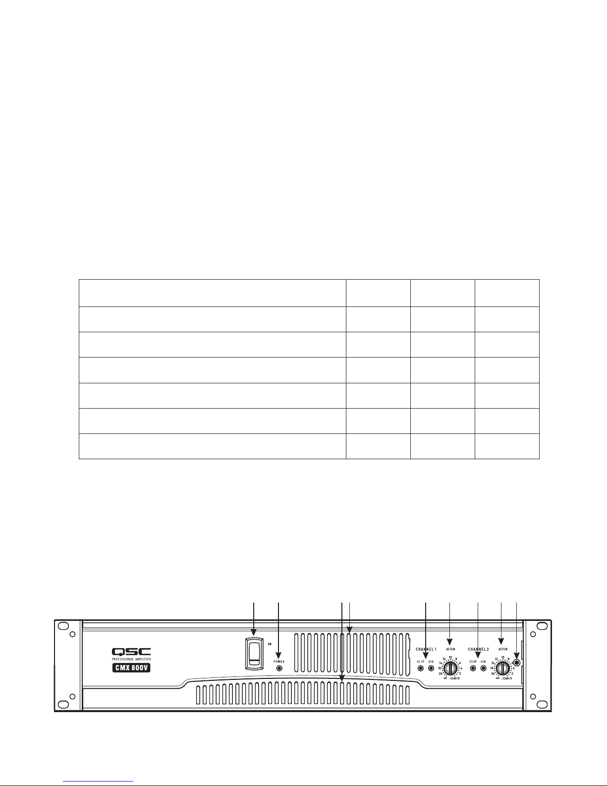
Front Panel
1. Power switch
2. Power indicator LED
3. Cooling vents
4. Clip and Signal indicator LEDs, (Channel 1)
5. Attenuation control (Channel 1)
6. Clip and Signal indicator LEDs, (Channel 2)
7. Attenuation control (Channel 2)
8. Lockout plate retention screw
– Figure 1 –
1 2 3 4 56 7
– Table 1 –
8

3
4
Back Panel
1. Barrier strip input
2. XLR inputs, Channels 1 and 2
3. Configuration dip switches
4. TRS inputs, Channels 1 & 2
5. Fan
6. Speakon™ output, Channel 1 and 2
7. Terminal block connector outputs, Channels 1 and 2
8. Circuit Breaker
9. Serial number label
10. Configuration switch chart
11. IEC power inlet (power cord connector)
Features and setup
Clip Limiter
What it is
When the audio signal drives the amplifier's output circuit beyond its power capability, it clips, flattening the peaks of the waveform. The clip limiter
detects this and reduces the gain to minimize the amount of overdrive. To preserve as much of the program dynamics as possible, limiting reduces the
average program level until peaks barely clip.
Each channel has its own clip limiter, and you can switch it on or off independently, as shown in (Figure 3).
When to use it (or not)
When driving full-range speakers, clip limiting reduces high-frequency distortion caused by bass overloads. It also protects higher frequency drivers
from excess overdrive and harsh clipping harmonics.
When driving subwoofers, some users let the amplifier clip without limiting because it gives extra “punch” to kick drums and similar sounds.
CAUTION: In bi-amp systems, excessive limiting will affect the frequency balance.
– Figure 3 –
123 95 6 8 10 114 7
12345679
810 11
– Figure 2 –

5
6
Input Filter
What it is
The low-frequency (LF) filter rolls off signals below either 30 Hz or 50 Hz (Figure 6 and 7). This improves bass performance by limiting sub-audio
cone motion, making more power available for the speakers' rated frequency range.
The filter settings for each channel are controlled individually through the DIP switch settings shown in (Figure 4). When the filter is turned off
(Figure 5), a 5 Hz roll off protects against DC or deep sub-audio inputs.
When to use it (or not)
As a rule, your speakers will sound better with proper filtering. Unless you already have filtering in a preceding device, match the setting to the low
frequency rating of your speakers. Vented (bass reflex, ported, etc.) speakers are especially sensitive to cone over-excursion at frequencies below their
rated limit.
The 50 Hz filter works well with most compact full-range speakers, and has a slight boost at 100 Hz for greater fullness. The 30 Hz filter is intended for
subwoofers and large full-range cabinets. The “off” position should be used only for applications such as studio playback monitoring, where you need
to know if there are unwanted sub-audio signals present in your mix.
– Figure 4 –
– Figure 5 –
– Figure 6 –
– Figure 7 –

5
6
Parallel Input Mode
What it is
The Parallel Input switches let you operate the amplifier in Parallel mode, delivering the same signal to both channels without using a Y cable. Each
channel drives its own speaker load, with independent gain, filtering, and clip limiting.
Set switch positions 4 and 5 to "PARALLEL INPUTS" to couple the inputs together (Figure 8). Turn the switches to "STEREO" for stereo, bi-amping, or
other 2-channel modes.
With the inputs in parallel, you can use the other set of input connectors to carry the signal to other amps (Figure 9). This is often called
a “daisy-chain.”
When to use it
Use the Parallel mode when driving two speakers with one input signal (Parallel mode) while keeping separate control of both channels' gain, filtering,
and limiting. Use Parallel mode and Bridge Mono mode to patch the signal to additional amplifiers through the extra input jacks.
Note: If you're using a balanced signal, use only balanced patch cables; even one unbalanced cable will unbalance the entire signal chain, possibly
causing hum.
Note: Turn off the “Parallel Inputs” switches when feeding the amp two separate signals.
– Figure 8 –
– Figure 9 –

7
8
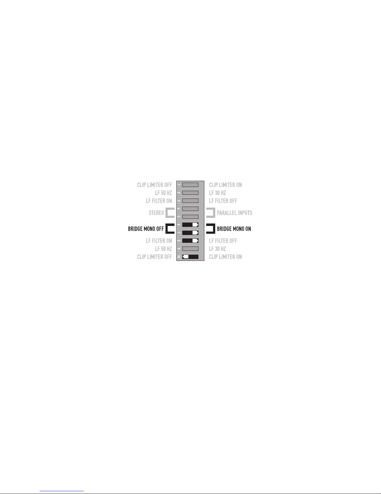
Bridge Mono Mode
What it is
Bridge Mono mode combines the power of both amp channels into one speaker, resulting in twice the voltage swing, four times the peak power, and
approximately three times the sustained power of a single channel. This mode uses Channel 1's input, attenuation control, input filter, and clip limiter;
Channel 2's dip switch settings should be in the OFF position, the attenuation control should be at maximum attenuation (Figure 10 and 11).
When to use it (or not)
Use Bridge Mono mode to deliver the power of both channels to a single 8 or 4Ωload. Set switch positions 6 and 7 to BRIDGE MONO ON
(Figure 10). Use Channel 1's inputs, and connect the speaker as shown in (Figure 12 and 13).
Bridge Mono Precautions
This mode puts a high demand on the amplifier and speaker, Excessive clipping may cause protective muting or speaker damage. Be sure the speaker
has a sufficient power rating.
Output voltages greater than 100 volts RMS are available between the bridged terminals of the CMX 800V. CLASS 3 wiring methods (NEC 1999), as
specified in accordance with national and local codes, must be used to connect the speaker.
To patch the signal to additional amplifiers, use
the parallel input switches described under
Parallel Input Mode.
Channel 2 settings, switches 8, and 10 are
set to off.
– Figure 10 – – Figure 11 –
– Figure 12 – – Figure 13 –
To speaker

7
8
The Difference Between Modes
Stereo Mode
Stereo mode is the typical way of using the amplifier. Each channel is fully independent. Separate signals connect at the inputs, the attenuation
knobs control their respective channels, and separate speakers connect to each output. The dip switches are set as shown in (Figure 14), a schematic
illustration in (Figure 15).
Examples:
• Two-channel (stereo) playback.
• Two independent mono signals, such as main and monitor mixes.
• Bi-amped operation, with the low frequencies in Channel 1 and the highs in Channel 2.
Parallel Input Mode
This mode is similar to the Stereo mode, except that the inputs for Channel 1 and Channel 2 are internally connected together. A signal into
Channel 1 jack drives both channels directly (Figure 16). Use Channel 1 Input, do not connect different sources to both channels. Each channel's
attenuation control still functions as usual, and each channel feeds its own speaker load. The dip switches are set as shown in (Figure 17).
In Parallel mode, you can patch the input signal on to additional amplifiers by using any of the remaining input jacks. See Ch. 2 in (Figure 16).
Example:
• One mono signal driving both channels, with independent attenuation control for each speaker system.
– Figure 15 –
– Figure 17 –
– Figure 16 –
signal input
NO INPUT!
Can be used to Daisy-chain
additional amplifiers
Amplifier #2
– Figure 14 –
9
10
Bridge Mono Mode
This mode combines the full power capabilities of both channels into a single speaker system. The amplifier internally re-configures so that both
channels operate as a unit. This delivers double the output voltage, resulting in four times the peak power and three times the sustained power into a
single 8 or 4Ωspeaker load. The Bridge Mono mode section on page 7 describes the special speaker connection used.
Examples:
• Driving a single 8Ωspeaker with the combined 4Ωpower of both channels.
• Driving a single 4Ω speaker with the combined 2Ωpower of both channels.
Precautions:
• Bridge Mono mode makes it possible to drive thousands of watts into a single speaker. AC current consumption will usually be higher. Avoid
excessive signal level, and make sure the wiring and speaker can handle the power.
• If the load is 4Ωor less and prolonged overloads occur, the amplifier will probably mute for several seconds during peaks, and the circuit breaker
may trip.
• Do not use 2Ωloads.
• Ensure Channel 2 dip switches are set to off (Figure 18), and Channel 2 attenuation control is set to maximum attenuation.
See the additional Bridge Mono precautions on page 7.
Set Channel 2 dip switches, 8 and 10, to off.
– Figure 18 –
This manual suits for next models
2
Table of contents
Languages:
Other QSC Amplifier manuals


