©
2020
Q-T
ran
Inc.
All
rights
reserved
|
155
Hill
St.
Milford,
CT
06460
|
203-367-8777
|
[email protected] |
www
.q-tran.com
Specification
subject
to
change.
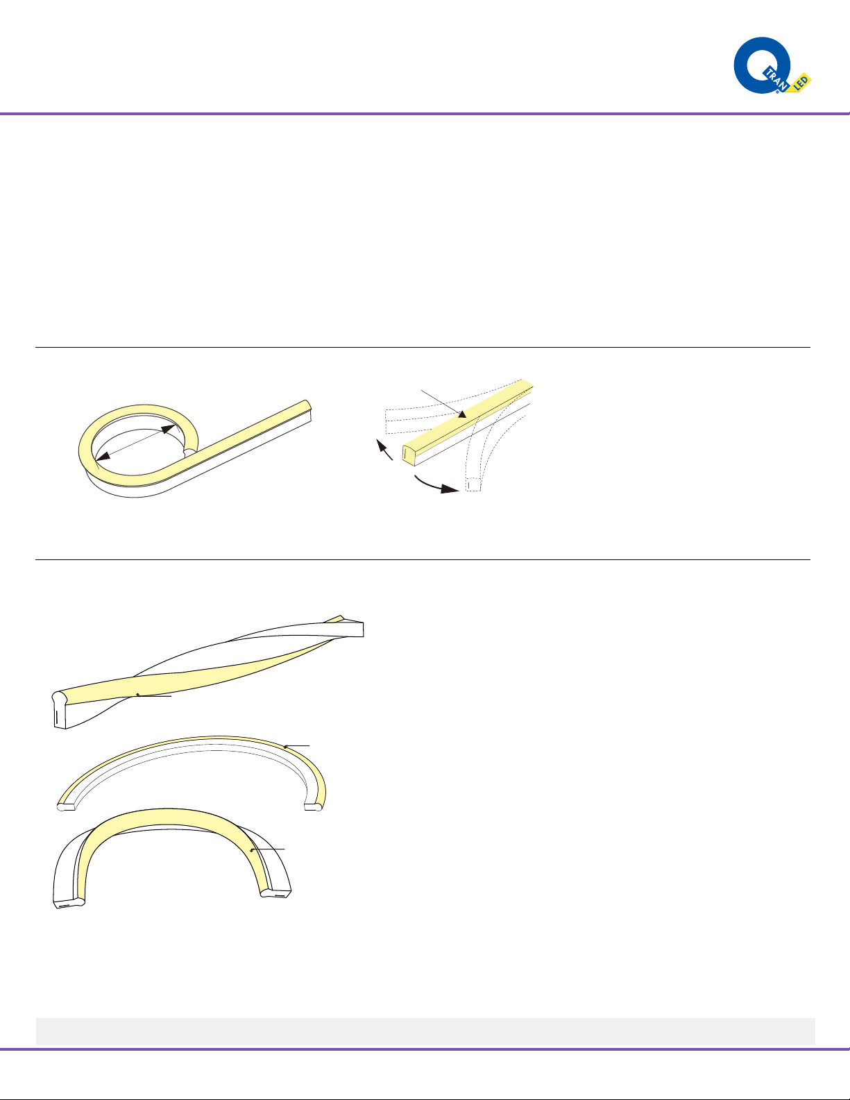
Rev-03-08-21INSTALLATION FLEX Light - FLEX Dome
NOTES:
• Field modifications must comply with Q-Tran’s installation methods otherwise warranty is null and void
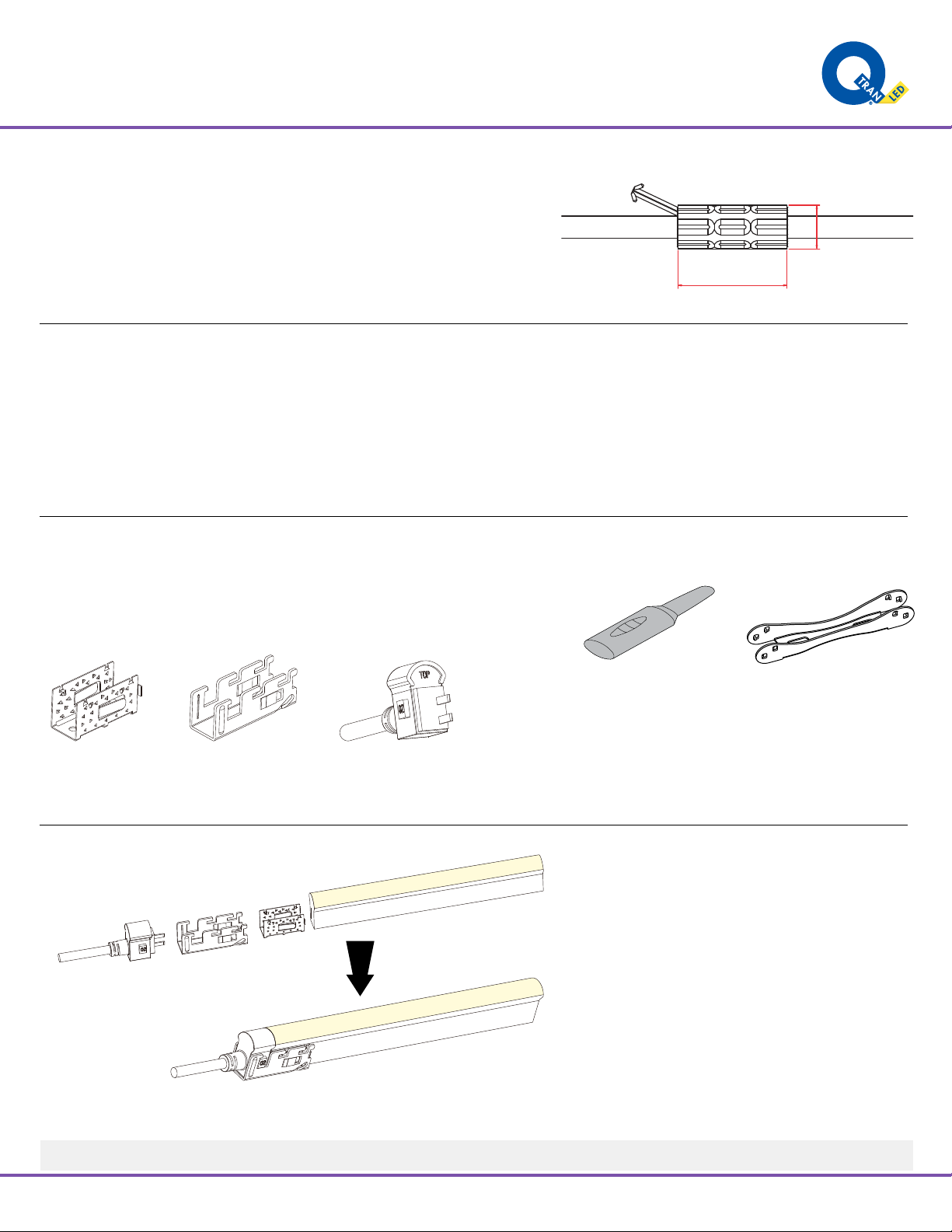
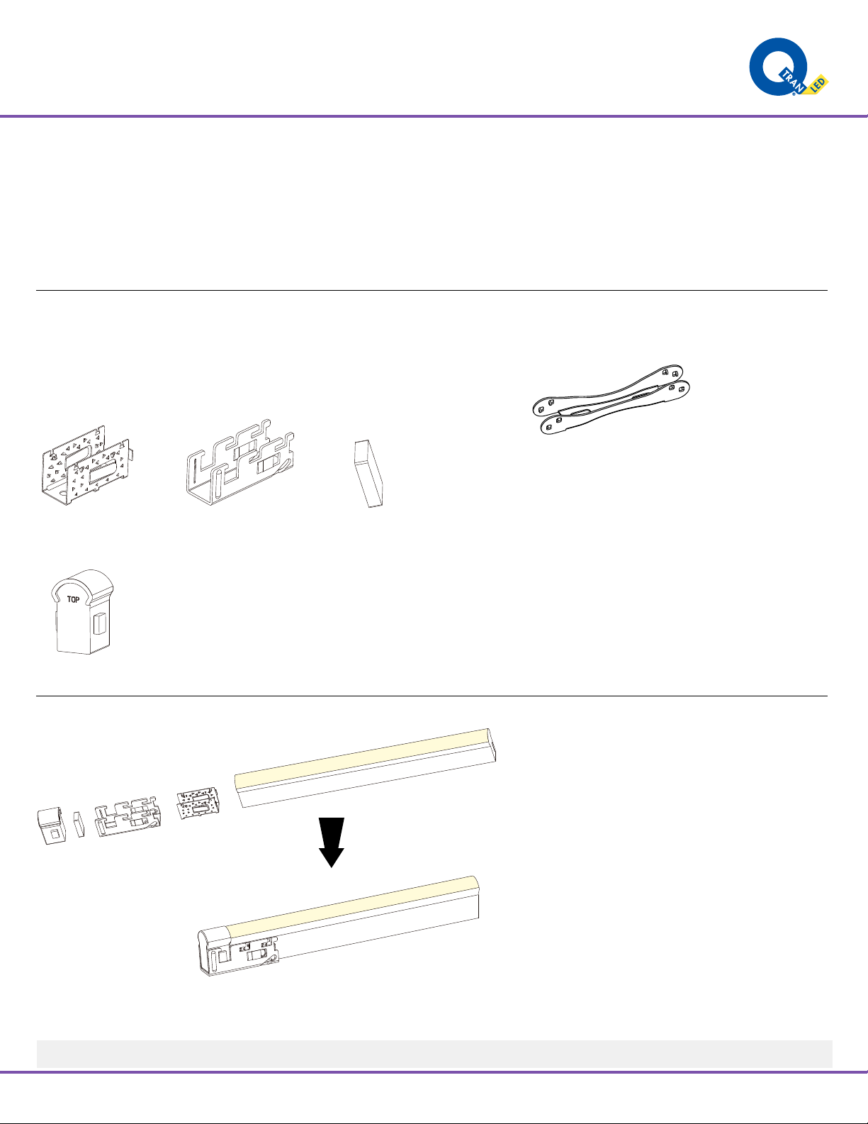
Clasp Front Connector
1. Inducing a Cavity for Feed Connector
2. Insert the Feed Connector
Insert the inducer to the backside of PCB around 0.39”-0.47”,
move the inducer up and down 3-5 times gently to create a
small cavity.
Insert the inducer into the backside of PCBIt will damage the light if inserted into front
side of PCB
PCB
PVC Tape
Insert the feed connector pins into the
cavity that you created with the
inducer (backside of PCB)
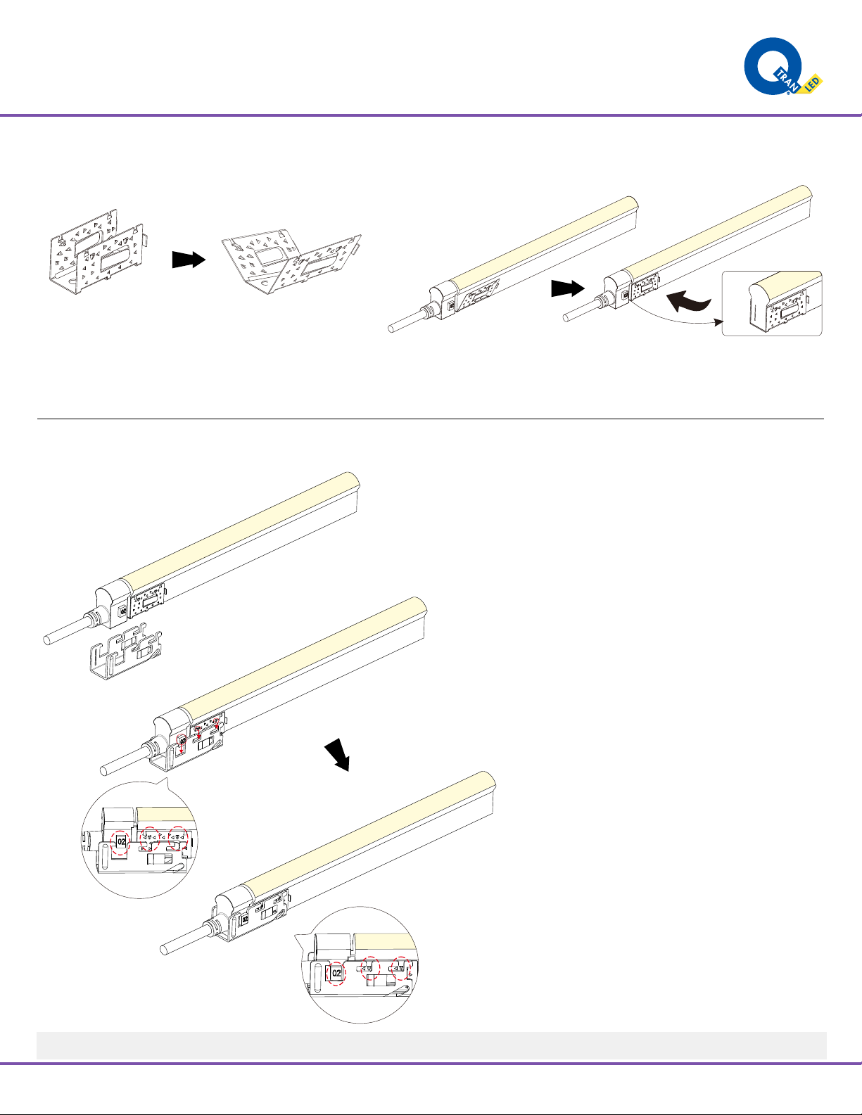
The following operations are prohibited:
Insert into the front side of the PCB
Insert crosswise into the PCB Insert crosswise into the PCB
NEVER insert into the front side
(LED side) of the PCB
The silicone gasket is attached on the feed connector.
Insert the inducer to the backside of PCB around 0.39”-0.47”,
move the inducer up and down 3-5 times gently to create a
small cavity.
t the inducer into the backside of PCBIt will damage the light if inserted into fron
side of PCB
PCB
Insertion Placement
PVC Tape
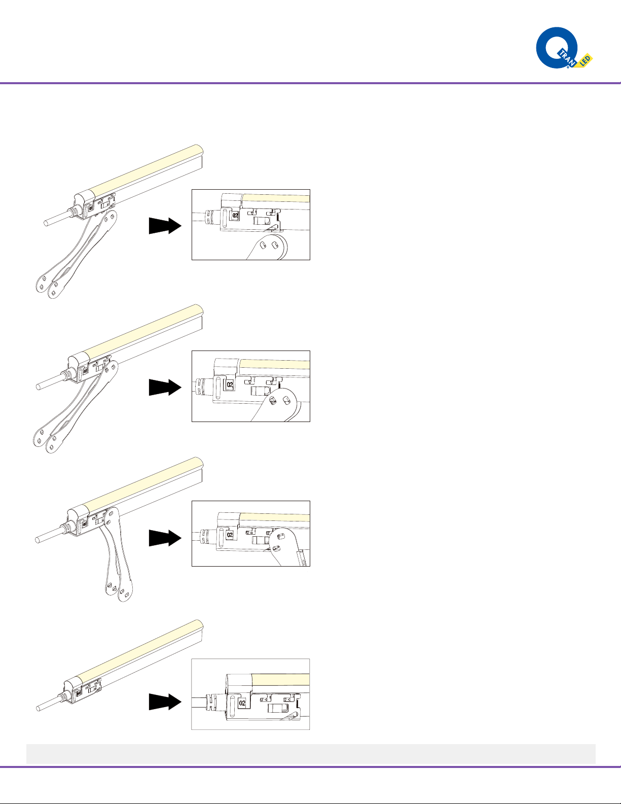
Insert the feed connector pins into the
cavity that you created with the
inducer (backside of PCB)
The following operations are prohibited:
Insert into the front side of the PCB
Insert crosswise into the PCB Insert crosswise into the PCB
NEVER insert into the front side
(LED side) of the PCB
The silicone gasket is attached on the feed connector.
Insert the inducer to the backside of PCB around 0.39”-0.47”,
move the inducer up and down 3-5 times gently to create a
small cavity.
Insert the inducer into the backside of PCBIt will damage the light if inserted into front
side of PCB
PCB
Insertion Placement
PVC Tape
Insert the feed connector pins into the
cavity that you created with the
inducer (backside of PCB)
The following operations are prohibited:
Insert into the front side of the PCB
Insert crosswise into the PCB Insert crosswise into the PCB
NEVER insert into the front side
(LED side) of the PCB
The silicone gasket is attached on the feed connector.