Rev-1115-12
© 2018 Q-Tran Inc. All rights reserved | 155 Hill St. Milford, CT 06460 | 203-367-8777 | [email protected] | www.q-tran.com | Specification subject to change | REQUIRED HARDWARE: per 12” installation
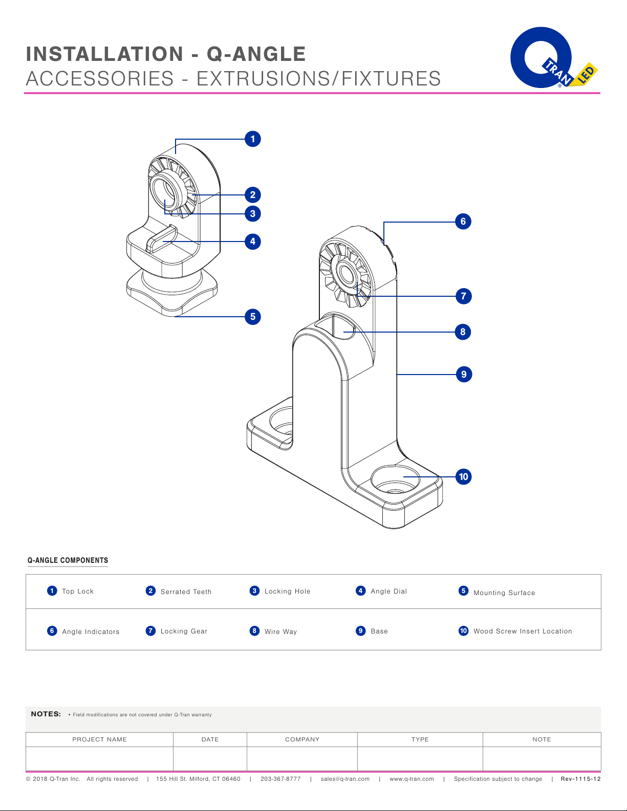
•2 x 6-32 Fillister head screw
•2 x 4-40 Flat head screw
•2 x Rigid Lock Channel & Retainer Clip
Shipped with fixture seperately
•2 x #8-32 Set Screw
Shipped with Rigid Lock Channel
•2 x Drywall anchors
For drywall applications only (not provided)
•4 x #6 Wood screw
•1 x 5/64 Allen Key
Shipped with Rigid Lock Channel
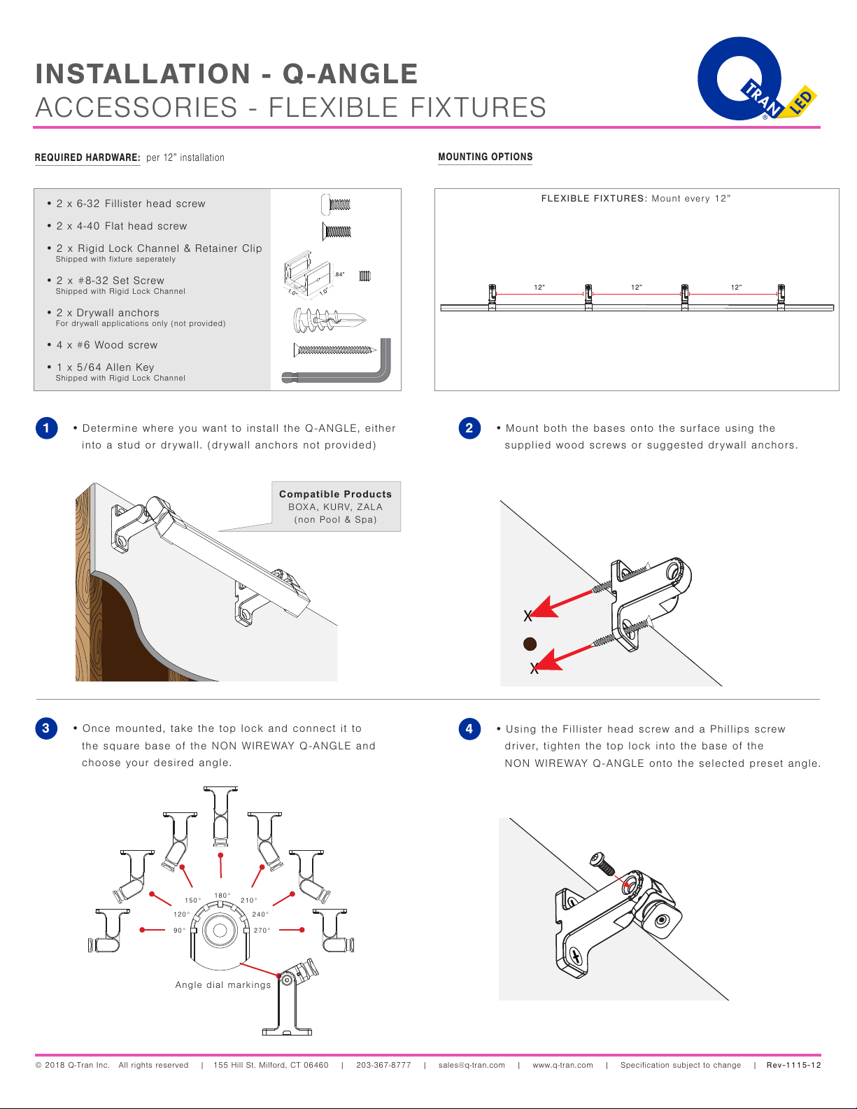
•Once mounted, take the top lock and connect it to
the square base of the NON WIREWAY Q-ANGLE and
choose your desired angle.
3
MOUNTING OPTIONS
•Mount both the bases onto the surface using the
supplied wood screws or suggested drywall anchors.
2
X
X
90° 270°
240°
210°
180°
150°
120°
•Determine where you want to install the Q-ANGLE, either
into a stud or drywall. (drywall anchors not provided)
1
Compatible Products
BOXA, KURV, ZALA
(non Pool & Spa)
Angle dial markings
INSTALLATION - Q-ANGLE
ACCESSORIES - FLEXIBLE FIXTURES
1.0”
FLEXIBLE FIXTURES: Mount every 12”
•Using the Fillister head screw and a Phillips screw
driver, tighten the top lock into the base of the
NON WIREWAY Q-ANGLE onto the selected preset angle.
4