Quaildigital Pro9 User manual

Pro9
Headset System
Installation Manual

page 2
This guide specifies how the Pro9 headset system should be installed and commissioned.
The LEDs on the base and headset use a sequence of colours, flashes and pulses to
indicate the status of the system and the item, which are explained in this guide.
CONTENTS
Preface page 3
Introduction page 3
What’s in the box page 3
Tools, cabling and equipment required page 3
Installation procedure page 4
Appendix A Installing Pro9 system using existing cabling to page 10
connect the base station to the DTM located in
the order point (Q-P9NTB x2)
Appendix B Installing Pro9 system using existing cabling to page 11
connect the base station to the DTM located in
the building (Q-P9JB x2)
Appendix C Pro9 auxiliary connections (Q-P9ACB) page 12
Appendix D Pro9 repeaters (Q-P9REP) page 13
Appendix E Pro9 table service (Q-P9BSTS) page 14
Appendix F Connecting a computer to Pro9 base station page 15
Appendix G Connecting a computer to Pro9 base station page 16
using a wireless adaptor
Appendix H Setting up Pro9 as dual lane/tandem configuration page 18
(Q-P9BSDL)
Appendix I Recording a‘Pull forward’ message page 20
Trouble shooting page 22
Manufacturer’s notes page 24
Headset transition table page 25
Regulatory notices page 26
Pro9 system components page 27

page 3
Preface
Quail Digital Pro9 is a wireless headset system designed to facilitate order-taking in the drive-thru lane
of a quick service restaurant. Team members wearing wireless headsets communicate with customers
through a remote order point containing a microphone and speaker which activate on arrival of
their vehicle at the post. Headset users can communicate with the customers, and on a private
channel, with each other. The system uses the internationally approved DECT telephony standard and
specification for transmission. Page 27 of this manual lists the components parts of the system. The
sale, installation and support of the product is undertaken by organisations and individuals known to
or appointed by Quail Digital.
Introduction
This manual is aimed at the technician level reader who is expected to be familiar with all safety
precautions relevant to the use of electrical equipment.
The Pro9 system differs from other drive-thru headset systems as it is digital all the way from the
order point to the headset. This improves audio quality, clarity and acts as a shield from external
interference.
If you are unfamiliar with Quail Digital products, you are encouraged to watch our training films
on this product before you start the installation, and to follow the installation steps in the order
presented in this guide.
Quail Digital uses direct burial Cat5 cable for the link between the order post and the base station
and always recommends that solution. Proprietary or recommended cables used by other headset
suppliers have been tested with Pro9 and can be used if already in the ground (subject to testing).
What’s in the box
•Pro9 Headset (Q-P9HS) (optional items)
•Pro9 Base Station (Q-P9BS) •Pro9 Repeater (Q-P9RP)
•Pro9 Charger (Q-P9CH) •Pro9 accessory kit
•Pro9 Drive-Thru Module (Q-P9DTM) -Junction Box (Q-P9JB)
•Pro9 Speaker & enclosure (Q-P9SPK) -Auxiliary Connection Box (Q-P9ACB)
•Pro9 Microphone & enclosure (Q-P9MIC) - Network Termination Box (Q-P9NTB)
•Acoustic foam (Q-P9FOAM)
Tools, cabling and equipment required
•Small terminal flat blade screwdriver •Cat5 patch lead
•Cordless drill •Cat5 cable tester
•Tape measure •Direct burial specification Cat5 cable
•Spirit level •RJ45 connectors (up to 4)
•Marker pen •Multimeter
•Cable strippers/diagonal side cutters •Stepladder
•Cat5 cable crimping tool •Laptop or phone for setup

page 4
Installation procedure
Step 1 The 8-port charger, power supply and metal hanger
are in the box (Q-P9CH). Wall mount the charger in the
manager’s office or other secure location close to a power
socket using the template provided in the box. There are two
key slots on the rear for mounting and one screw hole under
the cap in the third battery slot from the left on the bottom
battery row to secure the charger to the wall. Plug in the
power supply lead to the charger feeding the cable through
the securing gates. Attach the hanging bar before mounting
to the wall.
Step 2 Plug the power supply into a mains socket. The
power LED bottom right will illuminate RED. Insert each
battery into a slot. The individual LEDs will be solid red
when charging and turn solid green when fully charged. On
occasion new batteries may get warm during charging. If
this happens, the LED will go out and charging will stop to
protect the battery until it cools down, this is normal.
Step 3 Remove the microphone (Q-P9MIC) and speaker (Q-P9SPK) from their boxes. The microphone
is positioned against the top grill of the order point. Use the silver pre-drilled mounting bracket to fix
securely where you can. There should be no gap between the face of the microphone and the grill,
and the grill should have as many holes as illustrated in the diagram. If it doesn’t, consider drilling
more holes to maximise the effectiveness of microphone.
Step 4 Place the acoustic foam provided around
the microphone to provide extra acoustic protection.
Step 5 Use the same procedure as in Step 3 above
to mount the speaker against the lower grill; it does
not require the acoustic foam.
Figure 1 - Pro9 charger
Figure 2 - Order point assembly
Drive-Thru Module
Speaker
Microphone

Step 6 You now fit the Drive-Thru Module
(Q-P9DTM) into to the order point using the
flanges and four screws. If the DTM does not
fit or cannot be mounted in the order point,
go to Step 10.
Step 7 Next install a single length of direct
burial Cat5 cable from the DTM in the order
point, through the existing underground
conduit(s) to the likely location of the
base station (Q-P9BS) in the kitchen area.
Then, using your crimping tool, terminate
both ends of the cable with RJ45 plugs,
remembering to fit waterproof connection
cover provided onto the Cat5 at the DTM
end. Use your Cat5 tester to confirm a PASS
for a full 8 core test. Figure 4 shows the
colour code sequence for wiring the plug.
Step 8 Plug in the Cat5 cable and the
speaker and the microphone to their
respective sockets on the DTM as shown.
Step 9 Before connecting the loop to the
DTM ensure you have checked the loop
lead-in wires for continuity. If this test fails,
check/test or replace the loop as required.
If the test is successful, proceed to connect
loop lead-in wires to the screw terminals of
the DTM as shown, remembering to fit the
weatherproof cover provided.
Now go straight to Step 11.
page 5
PRO 9 DRIVE THRU MODULE
Q-P9DTM
Figure 3 - Pro9 Drive-Thru Module
brown
brown/white
green
blue/white
blue
green/white
orange
orange/white
Figure 4 - Type B RJ45 termination colour code
Figure 5 - Loop connection
Connection
to sonar
Connection
to mic
Connection
to speaker

Step 10 If the order point is physically too small to house the DTM OR if the ambient temperature
in the order point might exceed 40°C (104°F) on a regular basis, the DTM can be located internally.
In doing so you will need to cut and remake the speaker and microphone connections using the
Junction Boxes (Q-P9JB) - ordered separately. See Appendix B for this procedure.
Step 11 Choose a location to mount the base
station with as much clear space around it
to optimize the transmission range. Use the
template to locate the fixing holes. The power
supply should be close by.
Step 12 If there is a lane timer and/or a chime speaker to be connected to the system, the cables for
both need to be fed into an Auxiliary Connection Box (Q-P9ACB) which connects into the base station.
When completed, plug in the DIN plug into the base station and use the length of cable to mount the
auxiliary connection box out of sight in the ceiling or under a counter.
page 6
Figure 6 - Positioning the base station
Figure 7 - Connecting lane timer/chime speaker to the system

Step 13 Plug in the Cat5 cable from the DTM into the base station. On powering up the base station,
the speaker in the post will beep four times. This is the system carrying out checks to ensure that the
speaker and mic are connected properly and operational. The LED will flash amber and then turn
constant RED when ready and on standby. If the LED is flashing red or amber, see‘Trouble shooting’
on page 22.
Step 14 Now register the headsets to the base station. Take
the charged batteries and insert one into each headset.
The headsets will pulse white initially then red when not
registered. Hold the headset to the base station as shown.
The LED on the end of the boom will fast-flash green during
the registration process, then double pulse green when
registered. Repeat this process one at a time until each
headset is registered.
Step 15 To test the audio link to the order
point, have someone go out to the order
point. Press vehicle detection override
on the base station. The speaker in the
order point is live. Press ‘I’ on the headset
to talk with the person at the order point.
When you’ve spoken and heard the person
outside, the test is done. Press vehicle
detection override again to de-activate it.
page 7
Pin Colour Connection
1 White Chime Speaker +ve
2 Red Chime Speaker -ve
3 Blue Timer out Common
4 Green Timer out NO
5 Brown Timer greet +ve
6Grey Timer greet -ve
7 Purple Ext. Activation Common
8 Yellow Ext. Activation Detect
Power Connection to
timer & grill
speaker
Connection to
table service
if used
Cat5 cable
from DTM
Connection to
repeater
if used
Figure 8 - Connecting to base station (top)
Figure 9 - Registering the headset
Vehicle detection override
Figure 10 - Testing the audio link

page 8
Step 16 Set the road loop sensitivity so the arrival of every
vehicle is picked up accurately by the DTM.
a. Remove the lid from the DTM and then park an average
sized car (not SUV or van) on the road loop at the order point.
b. Identify the detector PCB in the DTM and then use the ‘Up’
and ‘Down’buttons to adjust the displayed number to 5 from
whatever it shows now.
c. Drive the vehicle off the loop and check the loop reading
returns to‘0’ and when the vehicle returns back onto the loop
make sure the number displayed is 5, then replace the lid.
Step 17 Now set the order point volume. The microphone
level is pre-set and is unlikely to need adjusting by you, but
the outbound volume through the speaker can be adjusted to
suit the local environment. To do this you need to access the
Pro9 settings menu as below which you do via your laptop or
cellphone (see Appendix F and G for access).
Step 18 Ask someone in a vehicle to drive to the order point. You’ll hear a beep in your headset to
signify a car is at the order point. Press‘I’, to talk, the headset will go into to handsfree mode and the
boom LED will go solid green. While speaking with the person at the order point, ask them if the
sound level is comfortable or too loud or too quiet. The default setting is usually fine. You can change
the volume levels as you see fit but be careful to judge whether the change will suit the everyday use
of the system once the store is operating.
Step 19 While in the settings menu, ask the customer whether they wish to operate with a SINGLE
order taker mode, or MULTIPLE order taker mode. The default is multiple order taker.
Figure 11 - Vehicle detector board, inside DTM

Step 20 Now explain the headset features to the customer:
In multi order taker mode: any headset wearer can take an order
from the order point when they hear the car arrival beep. A single
press of the ‘I’ button puts the order taker into handsfree mode
and the boom LED will go solid green. All other headsets hear the
conversation. When the vehicle leaves, the call closes automatically
and the LED boom will revert to double pulsing green. If another
user wishes to page other headsets, the user presses‘*’. The boom
LED turns white while the person is talking. Release to listen. When a
vehicle is detected the red LED on the base splits showing GREEN on
the bottom half.
In single order taker mode: there is one dedicated order taker at any
one time. Only that headset can communicate with the order point
until they are overridden by another user. The order taker’s boom LED
double pulses green, runner’s single pulses green. All users hear the
car arrival chime and hear the conversation between customer and
order taker. They can speak to the order taker during the order process
by pressing ‘*’and can speak with each other by doing the same. Any
runner can take over as order taker by pressing and holding ‘I’and‘–’
until their boom LED double pulses green. When a vehicle arrives
they should press ‘I’. They’re now the order taker and the previous
order taker becomes a runner (single pulse green). When a vehicle is detected the red LED on the
base splits showing green on the bottom half.
Step 21 Now show the customer the features on the underside of the base station.
a. If the site needs to reduce the order point noise level at night, they press the night volume button
and it stays activated for 8 hours or until they press again. The volume level is reduced by approx 20%.
The green light adjacent to the button indicates night volume is active.
b. If using a chime speaker the volume ‘+’ and ‘-’ buttons give manual adjustment to the sound level.
c. The vehicle detector is the manual override if the automatic vehicle detection fails.
d. The reset button cuts the power and
starts a reboot. Press this for 10 seconds;
the front light will start to flash green
after several seconds, then a short time
later turn amber. You may now release
the button and the system will reboot.
page 9
Figure 13 - Base station (underside)
Vehicle
detection
override
Night
volume
Chime speaker
volume manual
adjustment
Reset
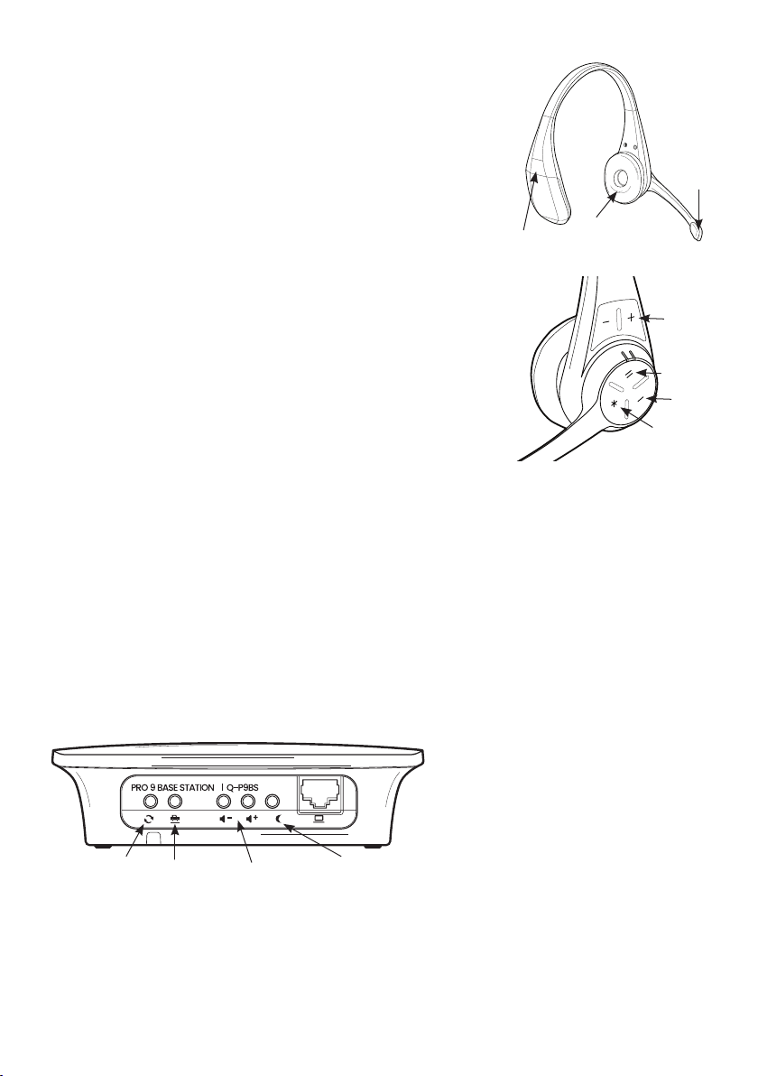
Figure 12 - Pro9 headset
Boom
LED
Battery
release
clip
Cushioned
earpiece
Volume
Lane 2
Lane 1
Page

page 10
Appendix A
Installing Pro9 system using existing cabling to connect the base station to the DTM located in
the order point (Q-P9NTB x2)
Using the network termination boxes allows existing cabling to carry digital signals and power on
previously installed cabling. Inside each is a small PCB with a network adaptor socket and screw
terminals, as below. Follow the steps below to make the correct connections.
1. Make and test 2 Cat5 patch leads at a length suitable for use, one inside and one outside. (You may
use bought Cat5 patch leads if preferred.) Fully test these leads.
2. Outside, strip back your existing cable and connect into the screw terminals of one of the network
termination boxes. Follow the colour codes in the table below.
3. Inside, again strip back the other end of your existing cables and connect into the second network
termination box. Follow the colour codes in the table below.
4. At the order point connect your Cat5 lead from the DTM into the network termination box.
5. Outside, connect the second Cat5 lead from the network termination box to the base station.
Different types of existing cables should be connected as follows.
Terminal connection
Cable type 1 2 3 4 5 6 7 8 Notes
4 core overall screened
22A WG with drain red black white nc nc green nc nc As used in many DT
installations
Specialist DT cable 3 pair
individually screened red black white nc nc blue nc nc Specialised cable
designed for DT
Multi pair screened cable
22A WG (use two pairs)
red
(pr1)
black
(pr1)
white
(pr2) nc nc black
(pr2) nc nc General purpose cable
suitable for DT
Figure 14 - Connecting using existing cabling to DTM in speaker post

Appendix B
Installing Pro9 system using existing cabling to connect the base station to the DTM located in
the building (Q-P9JB x2)
Using the junction boxes allows existing cabling to be used to carry the audio signals for the speaker
and microphone. Inside each is a small PCB with two sets of screw terminals, A and B as shown. Follow
the steps below to make the correct connections.
1. First, cut the cables on both the speaker and the microphone. Both have fixed cables, factory
terminated with specialist connectors.
2. Strip the cable of all 4 ends and prepare the cores for connection.
3. In the order point connect the microphone and speaker into the connection strip of the junction
box as shown following the colour codes.
4. Connect your existing audio cable to section B of the PCB as shown.
5. Then go to the other end of the audio cable in the building and use the other junction box to
attach the speaker and microphone plugs to it.
page 11
A B A B
Terminal connection Connector A
Installed cable type Spkr +ve Spkr -ve Spkr scrn Mic +ve Mic -ve Mic scrn Notes
Quail speaker & mic red black screen white blue screen Supplied installation
options
Terminal connection Connector B
Installed cable type Spkr +ve Spkr -ve Spkr scrn Mic +ve Mic -ve Mic scrn Notes
4 core overall screened
22A WG with drain red black nc white green scm
(drain)
As used in many DT
installations
Specialist DT cable 3 pair
individually screened red black nc white blue scm Specialised cable
designed for DT
Multi pair screened cable
22A WG (use two pairs) red (pr1) black
(pr1) scm (pr2) white
(pr2)
black
(pr2) scm (pr2) General purpose cable
suitable for DT
Figure 15 - Connecting using existing cabling to DTM in building

page 12
Appendix C
Pro9 auxiliary connections (Q-P9ACB)
If your system is using a lane timer and/or a chime speaker use an Auxiliary Connection Box and follow
these connection instructions:
Plug this interface connection unit into the corresponding connector on top of the base station.
This table provides the information you may require in relation to the auxiliary connections.
Figure16 - Auxillary connector box connections
Connection Colour Description Notes
1 White Chime speaker +ve For connection directly to a speaker to provide a chime on arrival of
a vehicle at the order point.
2 Red Chime speaker -ve
3 Blue Timer out common
0v switch output to provide vehicle detection to OEM timers or
other equipment.
4 Green Timer out NO
5 Brown Timer greet +ve
Simulated voltage output triggered when headset goes live to
speaker post. Provides “greet” function to OEM timers.
6Grey Timer greet -ve
7 Purple Ext activation common
0v to 12v detection to provide third party activation of the
headset system. Typically output from an OEM timer system.
8 Yellow Ext activation detect
Figure17 - base station (top)

page 13
Appendix D
Pro9 repeaters (Q-P9REP)
If the range needs to be increased you can add up to two Repeaters which, subject to local conditions,
doubles your headset range.
A repeater is another radio device and is wall mounted like the base station. Its power is fed down the
Cat5 cable which connects the repeater to the base station.
Two repeaters can be connected in a daisy chain format to a base station (as shown below).
1. Putting on a headset walk from the base station towards the area you require more coverage and
note where you lose connection.
2. Set up the repeater in the area where you need further coverage, connecting the Cat5 cable from
the base station to the repeater. Connect up.
3. Check that you have enough coverage for the additional area and that there’s full coverage in
hand-over zone where you lost range before.
4. Repeat the exercise if you need further increase in range, cabling back the second repeater to the
first repeater.
5. When your repeaters are booting up the LED on the front will flash AMBER, and then default to
solid GREEN in standby mode.
6. When the repeater is transmitting your headset audio, the LED will pulse GREEN.
7. See ‘Trouble shooting’for further guidance (page 22).
Figure18 - Increasing range using up to two Pro9 repeaters

page 14
Appendix E
Pro9 table service (Q-P9BSTS)
The Pro9 system can be configured to support two drive-thru order points and one
table service channel (TS).
If the restaurant is using table service, you will require a
Table Service Base Station. The table service base connects to the drive-thru base
station using a Cat5 cable and uses its own 48v power supply.
The table service base station is located in the seating area of the restaurant
because that is where the coverage is required. Usually, pick a location for the
base somewhere between the service counter and the entrance. If there are
multiple floors adjust your placement accordingly and consider adding one or
more repeaters.
1. Install a Cat5 cable from the drive-thru base station to the position you have identified for the table
service base station. Once installed use a Cat5 tester to ensure that the cable is fully wired and tested.
2. Mount the table service base station using the template provided as a guide for the screw locations.
3. Plug the Cat5 cable to the‘IN’port of the table service base station.
4. Return to the drive-thru base station and disconnect the power.
5. Plug in the new Cat5 cable to the‘OUT’ socket located on the top of the drive-thru base station.
6. Plug the power back into the drive-thru base station and table service base station.
7. After successful start up the LED on the TS base station will be solid amber.
8. Press the‘–’and the ‘*’ buttons of the headset together for 2 seconds, the boom LED will pulse
yellow, you can then let go of the buttons. You are now in table service mode.
9. Testing. Repeat Step 8 with another headset. Then,using the page ‘*’ button on one of the
headsets, the two headsets will communicate between each other.
10. The table service channel is simplex which means you push to talk and release when you’ve
finished speaking. When speaking the boom LED will be solid white.
11. To change your headset from table service to drive-thru press‘I’and ‘–’ . The boom LED will change
from pulsing amber to pulsing green.
Figure 19 - Table
service base station
Figure 20 - Connect table service base
station to drive-thru base station

page 15
Appendix F
Connecting a computer to Pro9 base station
To make adjustments to the Pro9 system you can connect a laptop directly into the comms port on
the bottom of the Pro9 base station. This appendix describes the process of making the connection.
This description is based on Windows 10, you may need to alter details to suit your operating system.
To provide communications a simple RJ45 network socket on the bottom of the Pro9 base station is
utilised. Connect a standard Cat5 lead from this socket to the network port of your laptop.
1. Press the Windows button on your keyboard and select the settings cog.
2. Select ‘Network and Internet’.
3. Select ‘Ethernet’, then ‘Change adaptor options’.
4. Right click on your ethernet connection and click ‘Properties’.
5. Double click on ‘Internet Protocol Version 4 (TCP/IPv4)’.
6. Select ‘Use the following IP address’and type in the IP address field 192.168.1.1, then in the Subnet
mask field type 255.255.255.0
7. Press ok on the open dialog boxes to close them.
8. Open your web browser and type into the address bar 192.168.1.115
9. This will now bring up the Quail API for you to change the settings of the base.
10. Once you are happy with your setup, follow the above steps again, however in step 6 select the
‘obtain IP address automatically’ to return your computer to normal settings.

Appendix G
Connecting a computer to Pro9 base station using a wireless adaptor
To make adjustments to the Pro9 system it is possible to complete this wirelessly using a WiFi
repeater/bridge. This appendix describes the process of making the connection. The use of the
interface API is described in the main manual.
This description is based on the Vonets VAP11G-300 WiFi
bridge. This device is a tool for the engineer and once
setup can be used on any Pro9 system to connect to the
installer API.
http://en.vonets.es/products/VAP11G-300/
1. Unpack the Vonets WiFi bridge and plug the USB into
your laptop, just to power the adaptor. Give the unit 30
seconds to start up.
2. Open the WiFi settings of your laptop or phone and connect to the Vonets WiFi network. The
password is ‘12345678’
3. Open a web browser and type in the address ‘192.168.254.254’
4. On the login page, enter username as ‘admin’and password as ‘admin’, both in lower case.
page 16

5. On the next menu, select ‘LAN settings’then ‘Static IP’
6. In the IP address box, change the address to ‘192.168.1.10’ and click ‘Apply’
7. The device will now say ‘Please wait’; once this is finished (approx 10 seconds), unplug the USB from
your laptop.
To use the wireless adaptor, you will need a power supply or battery pack to power the unit, a
standard USB charger power supply or battery pack will suffice. Once powered, plug the RJ45 into the
Pro9 base and open a web browser. Type ‘192.168.1.115’ into the browser and the Quail API will open
for you to make alterations to the settings.
Now this device is setup. See Step 18 in the main manual for details of the API.
page 17

page 18
Appendix H
Setting up Pro9 as dual lane/tandem configuration (Q-P9BSDL)
You will require two Q-P9BSDL base stations to operate two order points.
To configure two order point system, first follow Steps 1 to 13 in this manual. Essentially, treat it as
two separate single lane systems for initial installation and set-up. Once you have completed Step 13
follow the instructions below.
Note that each base station uses its own power. And note that if range extension is required a
REPEATER is required to be connected to each base station.
1. Disconnect the power from both base stations.
2. Identify which base station is connected to the first order point and connect a short Cat5 cable
from the ‘OUT’ port of this base station to the ‘IN’ port of the second base station.
3. Re-connect the power to BOTH base stations. The LED on the front of the lane 1 base station will
turn solid red. The LED on the lane 2 base station will turn solid GREEN.
4. Now follow Step 14 to register ALL the headsets to the system
using either base; the process is identical to that for single lane.
5. Now follow Steps 15 to 19 in the manual to set up the audio levels
at each order point. The setup process is done twice, separately, once
for each lane. Note than in dual/tandem lane configuration, there is
no ‘multi-order taker’ feature.
Figure 21 - Connecting dual lane stations
Units must
be at least
18” apart
Data link for dual lane operation
Base 1 Base 2

page 19
You will be asked to confirm whether the site is operating DUAL or
TANDEM lane. If you have selected tandem, you will be required to record
a ‘Pull forward’ message. Please go to Appendix I to read how to do that.
6. Once you’ve finished selecting mode and audio levels and recorded
the pull forward message in the case of tandem, press RESET. The system
is ready to be used, and you should explain the headset features to the
customer.
When you place a battery into a headset at the beginning of the day it always defaults to lane 1
runner. Review the table below to understand how to move from lane 1 runner mode.
Figure 22 shows the bottom of the base station.
When pressed, the third button from the left engages
‘Single Order Taker’ mode, where a single order taker
operates both lanes. Its default position (off) is one
order taker for each order point.
Single order taker mode
Action Standby Car arrival order point 1 Car arrival order point 2
All headsets
Insert battery. All
headsets become
order takers
Boom LED double
pulse green
Headset single beeps,
press ‘I’ to open channel.
LED changes to solid green
Headset double beeps,
press ‘II’ to open channel.
LED changes to solid blue
Dual order taker mode
Headset 1 Insert battery
Boom LED double
pulse green
Headset single beeps,
press ‘I’ to open channel.
LED changes to solid green
No action
Headset 2
Press ‘II’ and ‘–’
for 2 seconds.
LED changes to
double pulse blue
Boom LED double
pulse blue No action
Headset double beeps,
press ‘II’ to open channel.
LED changes to solid blue
Figure 22 - Additional data socket & function button
Order taker mode

page 20
Appendix I
Recording a‘Pull forward’ message
To use Pro9 in a tandem drive-thru you will need to record a ‘Pull forward’ message to the base station
for Lane 2. It is good practice to record the same message to both base stations in case they are
swapped around at a later date.
Procedure
1. Record your‘Pull forward’ message using a preferred audio/voice recorder, then rename the
recorded files to the required name in a known location of your computer.
2. Audio files need to be saved in mono (single track) and be encoded as: U-Law at 16 Khz. We
suggest using NCH Switch Plus (http://www.nch.com.au/switch) to convert your audio messages to
the correct format. It’s affordable for commercial use, and simple to use.
3. Open the NCH Switch program to the main screen, and then follow the steps outlined below:
a. Select ‘Output Format’ in the bottom left of the window, choose‘.wav’
a.
Other manuals for Pro9
2
This manual suits for next models
11
Table of contents
Other Quaildigital Headset manuals

Quaildigital
Quaildigital QP10HS User manual

Quaildigital
Quaildigital Pro11 User manual

Quaildigital
Quaildigital Pro9 User manual

Quaildigital
Quaildigital Pro9 User manual

Quaildigital
Quaildigital Q-P7BS User manual

Quaildigital
Quaildigital Pro10 User manual

Quaildigital
Quaildigital PRO7 User manual

Quaildigital
Quaildigital Q-HCBS User manual

Quaildigital
Quaildigital QP10HS User manual

Quaildigital
Quaildigital Q-P7BS User manual