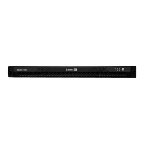
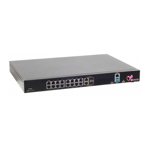
Quantum 1U User manual

[Classification: Protected]
24 April 2023
QUANTUM MAESTRO
Getting Started Guide

Table of Contents
Quantum Maestro Getting Started Guide|2
Table of Contents
Introduction
4
Overview
4
Shipping Carton Contents
5
Features
6
Speed and Throughput
7
Ports, Power Supply Units, and Fan Units
7
Getting Started with MHO-140 - Single Site with Two Orchestrators
8
Part 1 - Installing the Hardware and Connecting Cables
8
Part 2 - Initial Configuration on each Orchestrator
12
Part 3 - Configuration of Security Groups
15
Part 1 - Creating a New Security Group
15
Part 2 - Configuring Gaia Settings on the New Security Group
16
Part 3 - Configuring a Security Gateway Object in SmartConsole
17
Part 4 - Monitoring the Security Group Members
17
Hardware Components
18
MHO-140 Front Panel
23
MHO-140 Rear Panel
24
Ports
25
Mounting the Quantum Maestro Orchestrator MHO-140 and MHO-170 in a Rack
29
Connecting Cables to Quantum Maestro Orchestrators
41
Splitting the Ports with Breakout Cables
41
Breakout Cables
41
MHO-175 Splitting Options
43
MHO-170 Splitting Options
46
MHO-140 Splitting Options
47
Single Site
48
Connecting Two Quantum Maestro Orchestrators for Redundancy
48
Diagram
48
Workflow
55
Connecting Cables to MHO-140
59
Connecting to the Management Ports with DAC or Fiber Cables
59
Connecting to the Uplink Ports with DAC or Fiber Cables
61
Connecting to the Uplink Ports with Breakout Cables
63

Introduction
Quantum Maestro Getting Started Guide|4
Introduction
In This Section:
Overview
4
Shipping Carton Contents
5
Features
6
Speed and Throughput
7
Ports, Power Supply Units, and Fan Units
7
Quantum Maestro Orchestrator is a scalable Network Security System built to secure the largest networks in
the world by orchestrating multiple Check Point Security Appliances into a unified system.
The Quantum Maestro Orchestrator provides:
nSecurity of infinite scale
nRedundancy - Quantum Maestro Orchestrator automatically distributes traffic between the Security
Appliances assigned to Security Groups
nAbility to connect more Security Appliances and use their resources easily in the existing Security
Groups
Overview
Quantum Maestro Orchestrator 1U systems are ideal for leaf and spine data center network solutions that
provide maximum flexibility, with port speeds from 1 Gbit/sec to 100 Gbit/sec per port, and port density that
enables full rack connectivity to any server at any speed. The ports allow a variety of blocking ratios that suit
all application requirements.
Quantum Maestro Orchestrator 1U systems enable the use of 1, 10, 40 and 100 GbE port speeds in a large
scale without the need to change power infrastructure facilities.

Introduction
Quantum Maestro Getting Started Guide|5
Shipping Carton Contents
This section describes the contents of the shipping carton.
Item Description
Appliance Quantum Maestro Orchestrator
Rack Mounting Accessories n2 static (fixed) rack mount rails
n2 rack mount blades
n2 rack mount ears
n8 M6 standard cage nuts
n8 M6 standard pan-head Phillips screws
n4 flat head Phillips screws with a round patch
(6-32x1/4", 100-Deg, Patch 360)
Cables and Adapters n2 power cables (Type C13-C14)
n2 cable retainers
n1 DB9 to RJ45 serial console cable
n1 DAC cable, 3m
Documentation nQuick Start Guide
nPort Mapping
nUser license agreement
Table: Shipping Carton Contents
Notes:
nDB9 connectors are also known as DE9 connectors.
nBefore installing your new Quantum Maestro Orchestrator, unpack it and check the parts list to make
sure that all the parts are in the package.
Check the parts for visible damage that may have occurred during shipping.

Introduction
Quantum Maestro Getting Started Guide|6
Features
nThroughput and processing capacity:
lMHO-175 - Throughput of up to 3200 Gbit/sec and processing capacity up to 4.76 Bpps
lMHO-170 - Throughput of up to 3200 Gbit/sec and processing capacity up to 4.76 Bpps
lMHO-140 - Throughput of up to 1280 Gbit/sec and processing capacity up to 2.97 Bpps
nFlat latency in the cut-through mode:
lMHO-175 - 425 ns
lMHO-170 - 300 ns
lMHO-140 - 300 ns
nSpeeds of 1, 10, 40, and 100 GbE
nDynamically-shared, flexible packet buffering:
lMHO-175 - 42 MB
lMHO-170 - 16 MB
lMHO-140 - 16 MB
nLowest power, under 5 W per 100 GbE port
nEnhanced scalability
n1+1 hot-swappable power supplies
n4 N+1 hot-swap fans
nColor coded PSUs and fans

Introduction
Quantum Maestro Getting Started Guide|7
Speed and Throughput
The table below lists maximum throughput and interface speed for each Quantum Maestro Orchestrator
model:
Orchestrator
Model
10 GbE
SFP28 Interfaces
40 / 100 GbE
QSFP28 Interfaces
Maximal
Throughput
MHO-175 128
(use QSFP to SFP
breakout cables)
32 3.2 Tbit/sec
MHO-170 64
(use QSFP to SFP
breakout cables)
32 3.2 Tbit/sec
MHO-140 Total 64
48 SFP+ 8 QSFP28
(use QSFP to SFP
breakout cables)
8 1.28 Tbit/sec
Quantum Maestro Orchestrator supports different interfaces and speed rates when you use QSFP to SFP
adapters, or hybrid cables. For more information, see
"Splitting the Ports with Breakout Cables" on page41
.
Ports, Power Supply Units, and Fan Units
Orchestrator
Model MGMT Ports USB Ports Console Ports PSUs Fans
MHO-175 1 on the front
panel
1 on the front
panel
1 on the front
panel
2 units 4 units
MHO-170 1 on the front
panel
1 on the front
panel
1 on the front
panel
2 units 4 units
MHO-140 2 on the rear
panel
1 on the rear
panel
1 on the rear
panel
2 units 4 units

Getting Started with MHO-140 - Single Site with Two Orchestrators
Quantum Maestro Getting Started Guide|8
Getting Started with MHO-140 -
Single Site with Two Orchestrators
Part 1 - Installing the Hardware and Connecting
Cables
1. Mount the two Quantum Maestro Orchestrators MHO-140 in the racks on the site.
See
"Mounting the Quantum Maestro Orchestrator MHO-140 and MHO-170 in a Rack" on page29
.
2. Install the Security Appliances for your Security Groups.
Procedure
a. Install the applicable Expansion Line Cards (if required) in the appliances.
See
Installing and Removing Line Cards
.
Maestro configuration supports only ports 10 Gbps or faster.
b. Mount appliances in their racks.
See the
Getting Started Guide
for your appliances in sk96246.
c. Power on the Security Appliances.
3. Connect a DAC cable between the dedicated Synchronization ports 48 on the two Orchestrators.
For more information, see
"Port Mapping for the Quantum Maestro Orchestrator MHO-140" on
page20
.

Getting Started with MHO-140 - Single Site with Two Orchestrators
Quantum Maestro Getting Started Guide|9
4. Connect the required cables between the Security Appliances and the applicable 10 Gbps Downlink
ports 27 -47 on each Orchestrator.
More information
Important:
nMaestro configuration supports only ports 10 Gbps or faster on Security
Appliances.
nTo connect Security Appliances to these 10 Gbps Downlink ports, use a
Fiber cable or a DAC cable.
nTo connect Fiber cables, you must use only the supported transceivers.
See sk92755 - Compatibility of transceivers for Check Point appliances.
See:
n
"Port Mapping for the Quantum Maestro Orchestrator MHO-140" on page20
.
n
"Connecting Two Quantum Maestro Orchestrators for Redundancy" on page48
.
Diagrams:
Connecting cables between Downlink ports on each Orchestrator and 2 ports on the
Dual Port Card on each Security Appliance
Illustration Instructions
On each Security Appliance (C) in
the Security Group:
a. Connect a cable from Port 1
on the Dual Port Card to a
Downlink port on the first
Orchestrator (A).
b. Connect a cable from Port 2
on the Dual Port Card to a
Downlink port on the second
Orchestrator (B).

Getting Started with MHO-140 - Single Site with Two Orchestrators
Quantum Maestro Getting Started Guide|10
Connecting cables between Downlink ports on each Orchestrator and 1 out of 4 ports on
the Quad Port Card on each Security Appliance
Illustration Instructions
On each Security Appliance (C) in
the Security Group:
a. Connect a cable from Port 1
on the Quad Port Card to a
Downlink port on the first
Orchestrator (A).
b. Connect a cable from Port 2
on the Quad Port Card to a
Downlink port on the second
Orchestrator (B).

Getting Started with MHO-140 - Single Site with Two Orchestrators
Quantum Maestro Getting Started Guide|11
Connecting cables between Downlink ports on each Orchestrator and 2 out of 4 ports on
the Quad Port Card on each Security Appliance
Illustration Instructions
Important - In
R80.20SP, this
connection method is
supported only with the
R80.20SP Jumbo Hotfix
Accumulator (Take 105
and above) installed on
Orchestrators and
Security Groups.
On each Security Appliance (C) in
the Security Group:
a. Connect a cable from Port 1
on the Quad Port Card to a
Downlink port on the first
Orchestrator (A).
b. Connect a cable from Port 3
on the Quad Port Card to a
Downlink port on the first
Orchestrator (A).
c. Connect a cable from Port 2
on the Quad Port Card to a
Downlink port on the second
Orchestrator (B).
d. Connect a cable from Port 4
on the Quad Port Card to a
Downlink port on the second
Orchestrator (B).
Legend
Item Description
AFirst Orchestrator.
BSecond Orchestrator.
CSecurity Appliances in Security Groups.
A DAC cable connected to the dedicated Synchronization ports on the
Orchestrators.
Cables that connect odd ports on the Quad Port Card to the first Orchestrator.
Cables that connect even ports on the Quad Port Card to the second
Orchestrator.

Getting Started with MHO-140 - Single Site with Two Orchestrators
Quantum Maestro Getting Started Guide|12
5. Connect the required cables between the applicable Uplink ports 5-26,49 -55 on each Orchestrator
and your switches.
More information
Important - To connect Fiber cables, you must use only the supported
transceivers. See sk92755 - Compatibility of transceivers for Check Point
appliances.
See:
n
"Port Mapping for the Quantum Maestro Orchestrator MHO-140" on page20
n
"Connecting to the Uplink Ports with DAC or Fiber Cables" on page61
n
"Connecting to the Uplink Ports with Breakout Cables" on page63
Port Speed
on a Switch
Port Type on the
Orchestrator Cable to Use
10 Gbps SFP+ / SFP28
Ports 5-26
Fiber or DAC
40 Gbps QSFP / QSFP28
Ports 49 -55
Fiber, DAC, or Breakout
100 Gbps QSFP / QSFP28
Ports 49 -55
Fiber, DAC, or Breakout
6. Power on each Orchestrator.
See
"Step 7: Initial Power On" on page40
.
Part 2 - Initial Configuration on each
Orchestrator
Note - It is important in which order you configure the Orchestrators.
The first Orchestrator you configure becomes the "first" Orchestrator on this Site.
It synchronizes the configuration to the "second" Orchestrator on this Site.
Procedure
1. Connect the included Ethernet cable from your computer to the MGMT port labeled 0on the rear
panel of the Orchestrator #1.
See
"MHO-140 Rear Panel" on page24
.
You use this MGMT port only to manage the Orchestrator.

Getting Started with MHO-140 - Single Site with Two Orchestrators
Quantum Maestro Getting Started Guide|13
2. On your computer, configure a static IP address (see the documentation for your operating
system):
a. IP address - between 192.168.1.2 and 192.168.1.254
b. Subnet mask - 255.255.255.0
c. Default Gateway - empty
d. DNS Servers - empty
3. Open an SSH client and connect to this IP address - 192.168.1.1
4. Log in to Gaia Clish on the Orchestrator #1 with these default credentials:
nUsername - admin
nPassword - admin
Best Practice - Change the default password.
If the SSH connection is interrupted after the password change, log in again
with the new password.
More information
See the Gaia Administration Guide for your Orchestrator version:
n
R81.20 Gaia Administration Guide
n
R81.10 Gaia Administration Guide
n
R80.20SP Quantum Maestro Gaia Administration Guide
5. Activate the Orchestrator #1 - enter "y" when it asks you.
More information
This Orchestrator activation enables the Downlink ports and the Uplink ports.
For more information, see sk171784 - Activation of a Quantum Maestro Orchestrator.

Getting Started with MHO-140 - Single Site with Two Orchestrators
Quantum Maestro Getting Started Guide|14
6. Configure the IPv4 settings on the MGMT port on the Orchestrator #1 as required in your network.
Procedure
a. Configure the required IPv4 address and Mask Length:
set interface Mgmt1 ipv4-address <IPv4 Address> mask-length
<Length>
Example:
set interface Mgmt1 ipv4-address 192.168.10.22 mask-length 24
b. Change the state of the MGMT port to "on":
set interface Mgmt1 state on
c. Configure the required Default Gateway:
set static-route default nexthop gateway address <IPv4
Address> on
Example:
set static-route default nexthop gateway address 192.168.10.1
on
d. Save the configuration:
save config
7. Connect the MGMT port of the Orchestrator #1 to your network.
8. Make sure the connection from a computer on your network to Orchestrator #1 works.
More information
With a web browser, connect to this URL:
https://<IPv4 Address you configured on the MGMT port>
Example:
https://192.168.10.22
Notes:
nThere is no Gaia First Time Configuration Wizard on
Orchestrators.
nYou do not need to install a license on Orchestrators.
9. Repeat Steps 1 - 8 for the Orchestrator #2.
You must configure a different IPv4 address than that of the Orchestrator #1.

Getting Started with MHO-140 - Single Site with Two Orchestrators
Quantum Maestro Getting Started Guide|15
Part 3 - Configuration of Security Groups
Follow the Getting Started Guide section in the Maestro Administration Guide for your version:
n
R81.20 Quantum Maestro Administration Guide
n
R81.10 Quantum Maestro Administration Guide
n
R81 Quantum Maestro Administration Guide
n
R80.30SP Quantum Maestro Administration Guide
n
R80.20SP Quantum Maestro Administration Guide
THIS INFORMATION WILL BE ADDED TO THE MAESTRO ADMIN GUIDE FOR EACH VERSION
Part 1 - Creating a New Security Group
1. Connect with a web browser to Gaia Portal on the "first" Orchestrator.
https://<IPv4 Address you configured on the Orchestrator MGMT port>
Example:
https://192.168.10.22
2. Log in.
3. From the left navigation panel, click Orchestrator.
More information
The Topology section contains the table that shows these sections (from left to right):
Pane Description
Unassigned
Gateways
All detected Security Appliances that are not part of configured Security
Groups.
Topology Configured Security Groups with their assigned Security Appliances
and ports.
Unassigned
Interfaces
All interfaces on Orchestrators that are not part of configured Security
Groups.
4. In the middle pane Topology, at the top, right-click Security Groups and click New Security Group.
5. In the Security Group <X> configuration window, enter the required information, including the First
Time Wizard, and click OK.
6. From the left pane Unassigned Gateways, drag and drop at least one Security Appliance to the
Security Group’s Gateways section.
7. From the right pane Unassigned Interfaces, drag and drop at least one Management port (eth<X>-
Mgmt<Y>) to the Security Group’s Interfaces section.

Getting Started with MHO-140 - Single Site with Two Orchestrators
Quantum Maestro Getting Started Guide|16
More information
See:
n
"Port Mapping for the Quantum Maestro Orchestrator MHO-140" on page20
n
"MHO-140 ports on the front panel and their default names in Gaia" on page76
8. From the right pane Unassigned Interfaces, drag and drop the required Uplink ports to the Security
Group’s Interfaces section.
9. At the bottom of this page, click Apply.
10. Wait for the Orchestrator to create the new Security Group.
This process takes approximately 10 minutes, and it automatically reboots the assigned Security
Appliances.
11. Connect a cable between the assigned Management port (eth<X>-Mgmt<Y>) on the Orchestrator
front panel and your switch.
More information
See:
n
"Port Mapping for the Quantum Maestro Orchestrator MHO-140" on page20
n
"Connecting to the Management Ports with DAC or Fiber Cables" on page59
Part 2 - Configuring Gaia Settings on the New Security Group
1. Connect with a web browser to Gaia Portal on the Security Group (through the assigned Management
port eth<X>-Mgmt<Y>).
https://<IPv4 Address of Security Group>
Example:
https://192.168.10.66
2. Log in.
3. Configure the applicable interfaces and other settings.
More information
See the Gaia Administration Guide for your version:
n
R81.20 Gaia Administration Guide
n
R81.10 Gaia Administration Guide
n
R81 Gaia Administration Guide
n
R80.30SP Quantum Maestro Gaia Administration Guide
n
R80.20SP Quantum Maestro Gaia Administration Guide

Getting Started with MHO-140 - Single Site with Two Orchestrators
Quantum Maestro Getting Started Guide|17
Part 3 - Configuring a Security Gateway Object in SmartConsole
1. Connect with SmartConsole to the applicable Security Management Server / Domain Management
Server that must manage this Security Group.
2. Create a new Security Gateway and configure the required settings.
3. Configure the applicable rules in the Access Control Policy.
4. Configure the applicable rules in the Threat Prevention Policy.
5. Install the Access Control Policy on this Security Gateway object.
6. Install the Threat Prevention Policy on this Security Gateway object.
Part 4 - Monitoring the Security Group Members
1. Connect to the command line on the Security Group with an SSH client to:
<IPv4 Address of Security Group>
2. Run this command:
asg monitor
3. Wait for each Security Group Members to show its state as "ACTIVE".
This can take 6-7 minutes.

Hardware Components
Quantum Maestro Getting Started Guide|18
Hardware Components
This section provides a description of hardware components of Quantum Maestro Orchestrators.
Port Mapping for the Quantum Maestro Orchestrator MHO-175
Item Description Item Description
1 Port 1 is the Management port for
Security Groups
(leads to the Check Point
Management Server)
7 Management port (Mgmt1) for the
Gaia OS on the Orchestrator
2 Ports 2 – 16 are the Uplink ports 40
Gbps / 100 Gbps
(lead to external and internal
networks)
8 RJ45 port for Console connection
3 Ports 17 – 30 are the Downlink ports
(lead to Security Appliances)
9 Port 32 is the Synchronization
port on the same Site
(leads to the peer Orchestrator on
the same Site
4 Port 31 is the Synchronization port in
Dual Site
(leads to the peer Orchestrator on
another Site)
In the Split mode, the 4th split is Sync
and other splits are Downlinks
10 Button to select indication states
for the splitting control LEDs
5 Micro USB 2.0 port 11 Splitting control LEDs that show
the indication state for Port LEDs:
nState of which port to show
(without a split cable).
nState of which split port to
show (in 1-to-2 split, or 1-
to-4 split).
Legend

Hardware Components
Quantum Maestro Getting Started Guide|19
Item Description Item Description
6 System Health LEDs 12 Port LEDs that show the status of
all ports (including the split ports)
Legend (continued)
Port Mapping for the Quantum Maestro Orchestrator MHO-170
Item Description Item Description
1 Ports 1 - 2 are the Management port for
Security Groups
(lead to the Check Point Management
Server)
6 System Health LEDs
2 Ports 3 – 16 are the Uplink ports 40
Gbps / 100 Gbps
(lead to external and internal networks)
7 Port 30 is the Synchronization
port in Dual Site
(leads to the peer Orchestrator
on another Site)
3 Ports 17 – 29, and 31 are the Downlink
ports
(lead to Security Appliances)
8 Port 32 is the Synchronization
port on the same Site
(leads to the peer Orchestrator
on the same Site)
4 Management port (Mgmt1) for the Gaia
OS on the Orchestrator
9 RJ45 port for Console
connection
5 USB 2.0 port
Legend

Hardware Components
Quantum Maestro Getting Started Guide|20
Port Mapping for the Quantum Maestro Orchestrator MHO-140
Item Description Item Description
1 Ports 1 - 4 are the Management
port for Security Groups
(lead to the Check Point
Management Server)
7 Port 48 is the Synchronization port
on the same Site
(leads to the peer Orchestrator on
the same Site)
2 System Health LEDs 8 Port 56 is the Synchronization port in
Dual Site
(leads to the peer Orchestrator on
another Site)
3 Ports 5 – 26 are the Uplink ports 1
Gbps / 10 Gbps
(lead to external and internal
networks)
9 Management port (Mgmt1) for the
Gaia OS on the Orchestrator
4 Ports 27 – 47 are the Downlink
ports
(lead to Security Appliances)
10 Management port (Mgmt2) for the
Gaia OS on the Orchestrator
5 Ports 49 – 55 are the Uplink ports
40 Gbps / 100 Gbps
(lead to external and internal
networks)
11 USB 2.0 port
6 LEDs that show the state of the
split ports
when connecting Breakout cables
12 RJ45 port for Console connection
Legend
This manual suits for next models
3
Table of contents
Other Quantum Network Hardware manuals

Quantum
Quantum SMART-1 6000-L User manual

Quantum
Quantum TC2201E User manual

Quantum
Quantum CHECK POINT 16000 User manual

Quantum
Quantum VS2112-NVR User manual

Quantum
Quantum CHECK POINT SPARK 1500 Series Instruction Manual

Quantum
Quantum DXi4800 User manual

Quantum
Quantum MC300 Prism User manual

Quantum
Quantum DX Series User manual

Quantum
Quantum Prism FC470 User manual
Quantum
Quantum Scalar 50 Quick start guide