qubev EVON0040 User manual

INSTALLATION & OPERATION MANUAL
Universal Electric
Vehicle Chargepoints
7.4kW or 22kW Models
SIMPLE •COMPACT •AFFORDABLE

Support
Universal Electric Vehicle Chargepoints QUBEVM-V01-R0 Installation and Operation Manual
Page 1of 17 February 2023
Amendments
Amendment
Number Details Date
Ver 1, Rev 0 New Document. February
2023
Product: Universal Electric Vehicle Chargepoints
Applicable Models: Single-Phase Three-Phase
EVON0040 EVON0080
Document Type: Installation and Operation Manual
Document Code: QUBEVM-V01-R0
Language: UK English (Original)
Date Published: February 2023
One Stop Europe AB are the publishers of this document and own the rights to use the text, images and all technical content
contained within. Content supplied by third parties / partner organisations remains the property of that organisation and is used by
agreement with the supplier.
OneStop exercise care to ensure content is as accurate as possible at the time of publication. However, no guarantee of accuracy
should be inferred.
www.qubev.com
One Stop Europe AB
Mallslingan 20A, 187 66 TÄBY, Sweden

Support
QUBEVM-V01-R0 Installation and Operation Manual Universal Electric Vehicle Chargepoints
February 2023 Page 2of 17
Contents
Support 2
Safety 3
Safety Advice within this Manual 3
Product Specification 4
Physical Specification 4
Electrical Specification 6
Certifications and Compliances 6
Labelling 7
Unpacking 7
Typical Contents 7
Typical Options 7
Installation 8
Before Installation 8
Schematic Diagrams 9
Installation Procedure 11
Commissioning 13
Set the Charger Power 13
Completion 13
After Installation 14
Operation 14
Charger Status Indications 14
Charge a Vehicle 14
Maintenance 15
Fault Diagnosis 16
Disposal 16
Warranty 17
Support
For assistance with the installation or operation of this product, contact your preferred electrical
installer.
Translations of this manual are available online from:
www.qubev.com/downloads
Safety
Universal Electric Vehicle Chargepoints QUBEVM-V01-R0 Installation and Operation Manual
Page 3of 17 February 2023
Safety
This manual is provided as a guide to installation and operation and is specifically applicable to
the QubEV electric vehicle charger. Failure to install and operate the QubEV in accordance with
these instructions may damage the unit and invalidate the manufacturer’s warranty.
IMPORTANT: Installers and End Users must read and understand the content of
this manual before installation and/or use of the product.
Installation must only be performed by someone who is properly qualified and competent to do
so in accordance with the current legislation in force in the geographical location of the
installation.
xThe manufacturer/distributor cannot accept any responsibility for improper installation or
any problems arising from improper installation.
NOTE: Damage to the equipment, connected systems or to property caused by improper
installation are the responsibility of the installer.
xThe information provided in this manual must ONLY be used with the model(s) listed on page
1 of this manual.
xThe information provided in this manual must NOT be used with any other product.
xThe content of this manual may be updated by the manufacturer as required.
xDo NOT use the equipment for anything other than its intended purpose.
xDo NOT modify the equipment unless specifically instructed to do so by the manufacturer.
xDo NOT attempt to repair the equipment unless specifically instructed to do so by the
manufacturer.
xTo maintain electrical safety, the body enclosure of the product (access covers) must be
secured in their correct location using the supplied fasteners and the seal must be sufficient
to maintain the IP rating of the enclosure.
xFasteners used to mount the product in its working location must be sufficient for the task
and the specific mounting point.
xIf required, fasteners used to mount the product in its working location should be sealed to
maintain the IP rating of the enclosure.
xDamage to the product may render it unsafe. The product must be electrically isolated and
NOT used until appropriate remedial action has been performed.
Safety Advice within this Manual
This manual uses a system of warnings, cautions and notes.
xWARNINGS concern the safety of installers/end user and will be given before the
detail/instructions in the manual.
xCAUTIONS concern the potential for damage to the equipment and will be given before the
detail/instructions in the manual.
xNOTES are given to provide additional information and/or to highlight information of
importance. They will be given either before or after the detail/instructions as appropriate
and may use different wording (such as IMPORTANT) where emphasis is required.
Warnings, Cautions and Notes may be repeated several times as appropriate and may be
preceded by a hazard symbol where appropriate.
Product Specification
QUBEVM-V01-R0 Installation and Operation Manual Universal Electric Vehicle Chargepoints
February 2023 Page 4of 17
Product Specification
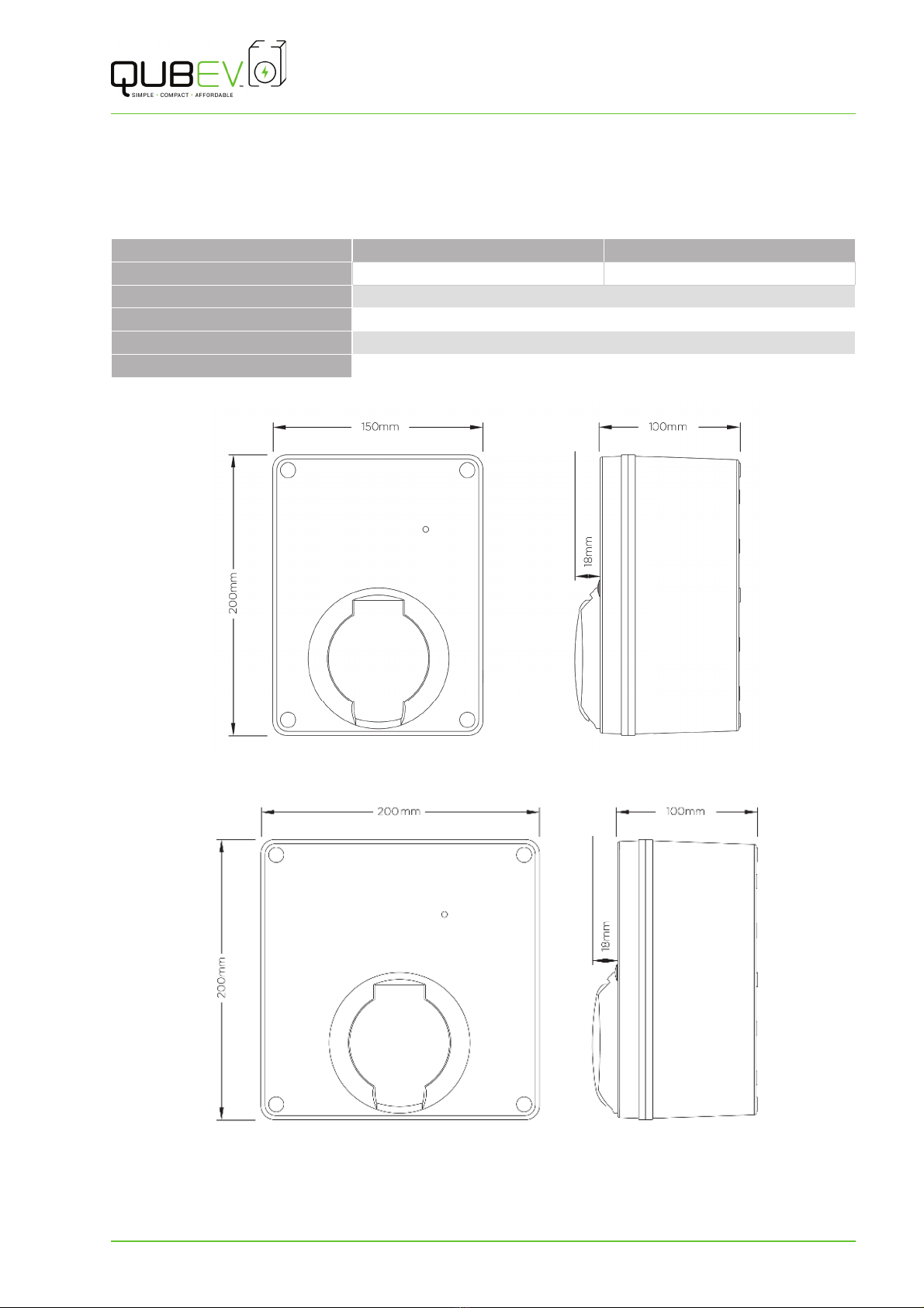
Physical Specification
EVON0040 EVON0080
Dimensions (W x H x D) 150 x 200 x 118mm 200 x 200 x 118mm
Materials ABS (UL94 HB Fire Rated), IK08
Mass <2.0kg
Operating Temperature -20°C to +50°C
Protection IP65 - Enclosure, IP54 - Socket
Figure 1 EVON0040 1-Phase Model
Figure 2 EVON0080 3-Phase Model
This manual suits for next models
1
Table of contents
Other qubev Batteries Charger manuals


