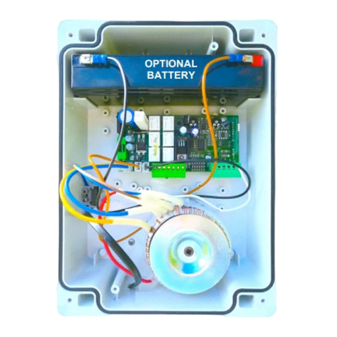
quiko QK-CE220CTN User manual

QK-CE220CTN
(1.3)
V05/2014

Contents
Page
1. INTRODUCTION 1
2. MAIN CHARACTERISTICS 1
3. TECHNICAL SPECIFICATIONS 1
4. INSTALLATION SAFETY 1
5. PRELIMINARY OPERATIONS 2
6. INPUT AND OUTPUT FUNCTIONALITY AND CONNECTIONS 2
6.1 J2 POWER TERMINAL BLOCK 2
6.2 J5 POWER TERMINAL BLOCK 2
6.3 J7 OUTPUTS/ACCESSORIES TERMINAL BLOCK 2
6.4 J9 INPUTS/OUTPUT TERMINAL BLOCK 3
6.5 J10 ELECTRIC BRAKE TERMINAL BOARD/ANTENNA 3
7. PROGRAMMING 4
7.1 BASIC FUNCTIONS 4
7.2 1ST LEVEL PROGRAMMING 5
7.3 2ND LEVEL PROGRAMMING 6
7.4 3RD LEVEL PROGRAMMING 7
8. 9
9
9
10
10
11
12
CONNECTIONS FOR SIMULTANEOUS OPERATION
13
9. TROUBLESHOOTING GUIDE
10. ATTENTION
11. EXAMPLES OF CONTROLLING ENTRANCES
11.1 INSTALLATION A CONTROLLED ENTRANCE OR EXIT
11.2 INSTALLATION B AUTOMATIC ENTRY OR EXIT
11.3 INSTALLATION C CONTROLLED ENTRY AND EXIT
11.4 INSTALLATION D CONTROLLED ENTRY AND AUTOMATIC EXIT

- 1 -
EV
EV
24 Vac
J10
F2
J9J7J5
J2
F1
F3
DL
SW1
J13
F
QK-CE220CTN
Instructions for installation and use
EN
The QK-CE220CTN control unit has been developed to control automatic bollards.
1. INTRODUCTION
3. TECHNICAL SPECIFICATIONS
2. MAIN CHARACTERISTICS
J2: 230Vac terminal board
J5: Power terminal board
J7: Outputs/accessories power supply terminal block
J9: Input/output terminal board
J10: Electrical brake terminal board
- Power supply: 230Vac +-10%, 50/60Hz
- Motor output: 230Vac; 3A max
- Accessory output: 24Vac; 1A max
DL: 2-digit display
SW1: “START” control button
F1: Line fuse: 5x20 8 A T
F2: Accessories and outputs fuse: 5x20 500mA T
F3: Low voltage fuse: 5x20 50mA T
F,+,-: Programming push buttons
LED
FCA
FCC
STOP
CLOSE
OPEN
PDM
START
FOTO
- Microprocessor logic
- LEDs displaying input status
- 2-digit display
-
TERMON
4. INSTALLATION SAFETY
In order to reach the level of safety required by current regulations, read the following prescriptions carefully.
1) Make all the connections in the terminal block after carefully reading the instructions given in this manual and observing the general
rules and technical standards governing electrical systems.
3) If there isn’t one already, install a residual current device with a threshold of 30 mA.
grounding
cable.
6) Fit all the safety devices required by the type of installation, taking into consideration the risks it can cause.
7) Separate the power lines (min. sect. 1.5 mm2) from the low-voltage signal lines (min. sect. 0,5 mm2) in the ducts.

- 2 -
5. PRELIMINARY OPERATIONS
- Before sending a command to the automation, make sure to have selected correctly the type of bollard as follows:
Bollard selection
- Hold down buttons F and + for 2 seconds to select the connected bollard.
- Select the type of bollard using the buttons +/-.
BOLLARD TABLE
QK-CT273600L QK-CT219500
QK-CT273800L/K4 QK-CT219700
QK-CT219500LFX QK-CT115500
QK-CT219700LFX QK-CT193700L
- Select network frequency through parameter.
6. INPUT AND OUTPUT FUNCTIONALITY AND CONNECTIONS
. (see 3rd level programming).
- (For QK-CT273600L/ 800L/ K4 only) Select the closing limit switch type (NO or NC) with parameter PP (paragraph 7.4) .
- Check the connection method for simultaneous operation if controlling multiple devices simultaneously (see
paragraph 9).
LINE 230V
230V 50/60Hz power supply with mov internal protection and 8A T fuse (5x20).
Connect the phase and neutral as shown on the screen printing. Use a cable type H07RN-F 2x1.5+E min.
Connect the yellow/green wire of the power supply mains to the earth terminal of the appliance.
OUT24
Output 24Vac, 1A MAX
LED (Cover lights)
Self-powered output. 24Vac, 100mA max
BZ (Cover buzzer)
Self-powered output. 24Vac, 100mA max
AUX
Programmable volt-free relay output, max. 500mA, 24Vac/dc. Use parameter
6.3 OUTPUTS/ACCESSORIES TERMINAL BLOCK
6.2 POWER TERMINAL BLOCK
LN E
24 Vac
LED
24 Vac
BZ
BZ
AUX
AUX
MOTA
COM
MOTB
CAP
EV
CAP
EV
SL
GR
RD
M
MOTA/OPEN
MOTB/CLOSE
Motor capacitor
Electrovalve (230Vdc) only QK-CT273600L/ 800L /K4
Flashing light (230V)
CAP
CAP
EV
EV
SL (Flashing light)
SLCOM
GR (green light)
RD (red light)
COM
6.1 POWER TERMINAL BLOCK

- 3-
-level 1.
FTC
N.C. safety input (photocell). Enter the programme wanted by programming the -level 1 parameter. It triggers only in
the closing phase; it never triggers in opening.
STOP
N.C. safety input. When it is activated, the automation is immediately stopped. During the pause time, a stop control
eliminates the automatic closing, leaving the bollard open waiting for a command.
FCA
Opening limit switch NC.
FCC (for QK-CT273600L / 800L/K4 only)
FTC
COM
STOP
COM
FCA
COM
FCC
COM
Closing limit switch. Select limit switch type (NO or NC) with parameter PP (paragraph 7.4)
START
N.O. input that operates the bollard’s opening and closing. The command is ignored while opening.
PDM
Input programmable with -level 3, -level 3 and -level 2 parameters. May be duplicated in AUX output.
OPEN
N.O. input - opening only.
By keeping this input controlled, the automation performs the opening manoeuvre and will close automatically only when
the input is freed. Connect clocks, daily timers or weekly timers here if wanted.
CLOSE
N.O. input for closing. It allows the automation to be closed only if the safety devices have not triggered. Operating
mode programmable with parameter
6.4 INPUTS/OUTPUT TERMINAL BLOCK
START
COM
PDM
COM
OPEN
COM
CLOSE
COM
6.5 J10 ELECTRIC BRAKE TERMINAL BOARD/ANTENNA
EF Electric brake output (not available for QK-CT273600L/ 800L/ K4)
Connection for two white power supply cables for the motor’s parking electric brake.
Activation is possible only when the bollard is completely lifted (12/ 24Vdc).
BT Input for anti blackout electric brake feeder (not available for QK-CT273600L/ 800L/ K4)
Permits the continuous power supply of the electric brake even without electrical energy, preventing the bollard
from lowering spontaneously in case of a blackout. Do not connect the batteries directly to this input but request
the original accessory QK-BPACKCT.
EF
BAT
+
SHIELD
ANT

7. PROGRAMMING
7.1 BASIC FUNCTIONS
To access programming, press button F for 2 seconds.
Programming is divided into 3 levels.
To go to the next level keep key F pressed and press the + key (Sequence 1 2 3 1.......).
After selecting the level wanted, press push button F to display the functions available in consecutive order. Each time F is pressed
it corresponds to a function ()+ () %" ,(.....)
With the function set, use the + or - key to change the values of the parameters ( + : -- -. -/ -0... / - : ...-0 -/ -. --).
The changes made to the parameters are active immediately but will be saved when exiting the menu, selecting the ST function
with key F.
PLEASE NOTE: If there is a black out when programming, all changes will be lost.
F- +
F
F
2nd level +/ 1"-2=arm closed
F
F
F
F
F
F
F
F
F
F
F
F F+
+
+
+
-
-
-
+
+
+
+
+
+
+
+
x 2”
x 2” x 5 x 3x 4
1st level
programming
Selects each
single 1st level
function
(see table par.6.2)
Selects each
single 2nd level
function
(see table par.6.3)
Selects each
single 3rd level
function
(see table par.6.4)
Changes the va-
lues of each single
1st level function
(see table par.6.2)
Changes the va-
lues of each single
2nd level function
(see table par.6.3)
Changes the va-
lues of each single
3rd level function
(see table par.6.4)
“ST” function
Exit and save
programming
2nd level
programming
3rd level
programming
Selecting Output2 on closed arm:
ABC D E
Example:

- 5-
7.2 1st LEVEL PROGRAMMING
The following table gives the 1st level functions and the single settable parameters.
Description of level 1 parameters
·: Functioning logic
- Hold-to-run: Close functions active for as long as control buttons are pressed. Open functions activated by pressing and
releasing control buttons. The start command opens once and closes once.
- Semi automatic: The automation works with jog commands, without automatic reclosing. Hence, when fully open, to control
closing you need to act on the start or close command respectively.
- Automatic: The automation works in jogs. When the opening manoeuvre is completed in the standard cycle, automatic reclo-
sing is activated after the pause time set (parameter ).
·
- : Close-when-released input
This mode has been developed so the bollard closes automatically only when the vehicle has completely passed by the
photocell or magnetic detector (the most suitable accessories for this purpose). Connect the N.O. contact of the detector or
photocell to the Close contact terminals.
tluafeDatadelbatteSnoitcnuFretemaraP
Selects the functioning logic.
(see notes after the table)
: Hold-to-run
: Semi automatic
: Automatic
(see notes after the table)
: Standard close input
: Close-when-released input
: The close command acts as a release closing and safety function.
Photocells
: During closure, it reopens and waits for the photoelectric cell free
commands.
: When closing it reopens; reclosing after 1’’ when the photocell is
disengaged
: When closing it reopens; reclosing after 5’’ when the photocell is
disengaged
Obstacle detection
(for QK-CT273600L/800L/ K4
only)
: Disabled
: When closing it stops and waits for commands
: When closing it reopens and waits for commands
: When closing it reopens, reclosing after 5 seconds
Bollard lights
bollard is opened and closed
ashing during movement and with bollard closed, cover
Buzzer : Buzzer off
: Buzzer on during movement
Resetting default parame-
ters. (see notes after the
table)
: No resetting
: Resetting the default parameters.
Apa-
rameters (see chapter 12.1)
Bpa-
rameters (see chapter 12.2)
Cpa-
rameters (see chapter 12.3)
Dpa-
rameters (see chapter 12.4)
Pause time
(expressed in seconds) -
Exiting the menu/saving Exit programming and view machine statuses (see notes St automation
statuses display)

- 6-
tluafeDatadelbatteSnoitcnuFretemaraP
Request for maintenance
: disabled
Programming maintenance
cycles in thousands
Programming maintenance
cycles in millions . . .
AUX output
: scheduled maintenance required
: photocell triggering
: obstacle detection
: PDM contact actuated
: bollard closed
: bollard open
: stop contact actuated
: start contact
: open contact
: blackout (the contact is activated when turned on)
: assistance required
TERMON : motor temperature increase in °C
Deceleration rotation torque
(not available for
QK-CT273600L/ 800L/ K4)
Exiting the menu/saving Exit programming and view machine Statuses (see notes automation
Statuses display after the 1st level table)
7.3 2nd LEVEL PROGRAMMING
The following table gives the 2nd level functions and the single settable parameters.
If the vehicle is on the detector or in front of the photocell it does not cause immediate closing but rather you have to wait for
the signal to be released.
- : The close command acts as a release closing and safety function.
When closing, the close command engaging stops the automation. When disengaged the bollard resumes closing.
·: Default
- To reset the default parameters, set parameter on 1 and exit the menu’.
A, B, Cand D, set the corresponding
default and quit the menu. See chapter 12 for details on installation type.
· : Automation statuses display
d.
The statuses are:
: Idle
: Opening
: Stop opening limit switch
: Stop opening
: Closing
: Stop closing limit switch
: Stop closing
: Stop due to photocell triggering
: Opening due to photocell triggering
: Photocell triggering pause
: Stop due to a detected obstacle
: Opening due to a detected obstacle
: Obstacle detection pause
: Maximum working time in opening reached
: Maximum working time in closing reached
Description of level 2 parameters
·: Request for maintenance
- : the request for maintenance is not active.
- : at the end of the countdown period, timed by the counters and , the programmed output is activated (see parameter
)
- : at the end of the countdown period, timed by the counters and , the programmed output is activated (see parameter

-7-
Description of level 3 parameters
·: Input polarity
· : Output polarity
·: Enable command during the pause time
Depending upon the setting of automation accepts or rejects commands for opening.
·: Special PDM functions
=1 PDM is used as opening consent. As long as it is not pressed, no opening command is accepted. When the PDM is
held down, no closure command is accepted so the bollard remains open.
=2 The PDM functions as described in point 1, but in case of automatic logic, the pause time is reloaded.
=3 The PDM function enables the TERMON system. Based on the setting of the parameter, the closing or opening of
the contact activates or deactivates the TERMON system. This makes it possible to interface with a calendar or ther-
mostat with a volt free contact to optimise the heating system.
Output AUX polarity : N.C.
Commands during pause : OFF
: ON
Special PDM functions
programmable input
: None
: Opening consent
: Opening consent and pause time reset (With dF = 04)
: TERMON enabling
Select frequency
Exiting the menu/saving Exit programming and view machine statuses (see notes St auto-
mation statuses display after the 1st level table)
Closing limit switch type
selection.
(QK-CT273600L / 800L/ K4 only)
: N.O. (for bollards supplied before 01/01/2013 )
: N.C. (for bollards supplied after 01/01/2013 )
tluafeDatadelbatteSnoitcnuFretemaraP
PDM dynamic input polarity : input N.O.
: input N.C.
: N.O.
7.4 3rd LEVEL PROGRAMMING
The following table gives the 3rd level functions and the single parameters.
·-: Programming maintenance cycles in thousands and millions
Thanks to the combination of the two parameters the countdown can be set after which a request for maintenance is signalled.
Thousands can be set with the parameter, millions with the parameter. Example: to set 275,000 maintenance manoeu-
vres set on 0.2 and on 75. The value displayed in the parameters updates along with the manoeuvres.
· =11: Assistance required
failure of the travel stop or the solenoid valve (QK-CT273600L/800L/K4
flashing of the cover lights.
· : TERMON
Must be activated with the ambient temperature where the bollard is installed (Tamb) drops below the minimum operating
temperature of the bollard itself (Tmin).
Sets the temperature difference between the bollard’s motor and the ambient temperature in centigrade degrees.
If the parameter is not zero, the control unit will heat the motor in order to obtain the set temperature difference.
Example: =15. The control unit will ensure that the motor maintains a temperature that is 15° above the ambient tempera-
ture.
By setting the parameter =3, it is possible to enable or disable the Termon system, operating directly on the PDM input.
= Tmin - Tamb_min + 5 (°C). Example: Tmin= -15°C, Tamb_min= -30°C, set = 20.
The heating function may be activated from a thermostat connected to the PDM input, and calibrated to switch when Tamb <
Tmin+5°C.
Alternatively, a timer clock may be connected to the PDM input with a calendar which activates heating during cold seasons.
· : Deceleration rotation torque
Sets the deceleration speed at the end of the closing manoeuvre.
The value of the deceleration speed at the end of opening is preset by the company.
: Opening consent and pause time reset (With dF = 05)

- 8 -
9. TROUBLESHOOTING GUIDE
In the case of a malfunction, check that the correct bollard was selected (paragraph 5)
, ,
stop and
the pressure switch contact at the end of closing (QK-CT273600/ 800L/ K4 only)
10. ATTENTION
It is recommended to make an installation which has all the accessories necessary to ensure operation according to current provi-
sions, always using genuine QUIKO devices.
This equipment must be installed and used in strict compliance with the manufacturer’s instructions. The manufacturer cannot be held
responsible for any damage deriving from improper or unreasonable use.
QUIKO disclaims all liability for any inaccuracies contained in this booklet and reserves the right to make changes at any time without
any prior notice whatsoever.
The control unit QK- CE220CTN is used to operate up to a maximum of four bollards connected in parallel to thus obtain simultaneous
operation with just one control panel.
Use a junction box with adequate protection rating to complete the connections between the bollards in order to avoid cumbersome joints
near the control panel.
MOTOR CABLES: Connect them in parallel respecting the polarity of the motors and joining the black cables, the brown
cables and the blue cables together.
CONDENSER CABLES: Connect the condensers (with which each bollard is equipped) in parallel between the black cables and
the brown cables of the motor cables.
ELECTRIC BRAKE CABLES: Connect the WHITE cables of the electric brakes in parallel (not available for QK-CT273600L/ 800L),LIGHT CABLES: Connect the YELLOW cables of the LED lamps in parallel.
FCA CABLES: Connect the GREEN cables of the opening end-of-travel devices in series.
FCC CABLES: For QK-CT273600L / 800L,bollards supplied before 01/01/2013
BURGLAR CABLES: Connect the ORANGE cables of the burglar device contact in series, ifavailable
HEATING ELEMENT CABLES: Connect the RED cables of the heating element in parallel, if available
FCC CABLES:
Connect the WHITE cables of the closing limit switch in parallel
For QK-CT273600L / 800L,bollards supplied after 01/01/2013Connect the WHITE cables of the closing limit switch in series
8. CONNECTIONS FOR SIMULTANEOUS OPERATION
+
J10
1FE 2FE 3FE 4FE
CCF
ACF
TNA
BAT
FE
DLEIHS
MOC
ST PO
CTF
MOC
ESOLC
NEPO
MDP
START
HCdn2
XR A5,0V42xaM
XUA A5,0V42xaM
DR
RG
LS
VE
PAC
BTOM
MOC
OM TA
42 V 1,0ca A xaM
DEL
ZB
42 V 1,0ca A xaM
W04V032
W04V032
W04V032
1CCF 2CCF 3CCF 4CCF
1ACF 2ACF 3ACF 4ACF
J9
J7J5
J2
220-230V ~
50-60Hz
NC
NC
NO
NO
NO
NO
1ZB
1VE
1paC 2paC 3paC 4paC
2VE 3VE 4VE
2ZB 3ZB 4ZB
42 V 1,0ca A xaM 1DEL 2DEL 3DEL 4DEL
1M
DRALLOB
1
DRALLOB
2
DRALLOB
3
DRALLOB
4
2M 3M 4M
FN
ON/NETON/SETON/SETON/ETON T :SA
/rofelbaliavatoN/repelibinopsidnoN
/rüfrabgüfrevthciN/ruopelbinopsidnoN
arapelbinopsidoN
/ruoptnemeuqinU/rofylnO/repoloS
arapolóS/rüfruN
a
b
b
a
b
QK-CT273600L/ 800L/ K4

9
DIMENSIONS
This solution is recommended when you want to enter a reserved area in just one direction activating a recognition command (radio
control, proximity key, magnetic keys, etc.).
Connect the N.O. contact of the S1 loop receiver to input PDM.
Connect the N.O. contact of the S2 loop receiver to input CLOSE.
The dimensional values of the loops are only approximate.
We suggest installing the QK LDT metal mass detector.
The vehicle approaches
the reserved area.
When the vehicle is on loop S1
the device will move down only
after a recognition command.
If the device is moving back up
and you want to lower it again
the vehicle must be on loop S1
and then you must activate the
recognition command.
When the vehicle is no longer
on loop S2 the device will
move back up.
Loops S1 and S2 also have a safet function in that the will not let the device move all the time the vehicle is on top.
ONE DIRECTION
ONE DIRECTION
ONE DIRECTION
ONE DIRECTION
11. EXAMPLES OF CONTROLLING ENTRANCES
11.1 INSTALLATION A CONTROLLED ENTRANCE OR EXIT
PARAMETER DATA DESCRIPTION
The close command acts as a release closing and safety function.
Opening consent

10
DIMENSIONS
This solution is recommended when you want to allow entry to a reserved area, entering or leaving without using the recognition com
mands, allowing transit of vehicles in just one direction.
The vehicle approaches the re
served area.
Occupying the coil S1 activates
bollard’s descent.
When the vehicle is no longer on
loop S2 the will move back up.
Loops S1 and S2 also have a safet function in that the will not let the device move all the time the vehicle is on top.
Connect the N.O. contact of the coil receiver S1 to the OPEN input.
Connect the N.O. contact of the S2 loop receiver to input CLOSE.
The dimensional values of the loops are only approximate.
We suggest installing the K-LDT metal mass detector.
*
11.2 INSTALLATION B AUTOMATIC ENTRY OR EXIT
ONE DIRECTION
ONE DIRECTION
ONE DIRECTION
PARAMETER DATA DESCRIPTION
The close command acts as a release closing and safety function.

11
This solution is recommended when you want to enter a reserved area in both directions activating a recognition command (radio
control, proximity key, magnetic keys, etc.).
The vehicle approaches the reserved area.
When the vehicle is on loop S1 the
device will move down only after a
recognition command.
If the device is moving back up and
you want to lower it again the ve
hicle must be on loop S1 and then
you must activate the recognition
command.
When the vehicle is no longer on
loop S2 the device will move back
up automatically after an adjusta
ble pause time.
The vehicle approaches the reser
ved area.
ENTRY
EXIT
DIMENSIONS
Connect the N.O. contact of the coil S1 and S2 receiver to
input PDM.
The dimensional values of the loops are only approximate.
We suggest installing the K-LDT metal mass
detector.
When the vehicle is on loop S2 the
device will move down only after a
recognition command.
If the device is moving back up and
you want to lower it again the ve
hicle must be on loop S1 and then
you must activate the recognition
command.
Loops S1 and S2 also have a safet function in that the will not let the device move all the time the vehicle is on top.
When the vehicle is no
longer on loop S1 the
device will move back
up automatically after
an adjustable pause
time.
11.3 INSTALLATION C CONTROLLED ENTRY AND EXIT
PARAMETER DATA DESCRIPTION
Functioning logic: Automatic
Pause time
Opening consent and pause time reset

- 12 -
This solution is recommended when you want to enter a reserved area in both directions. To enter, transit is allowed by means of a
recognition command while exiting is automatic.
EXIT
When the vehicle is no longer on
loop S2 the device will move back
up automatically after an adjustable
pause time.
The vehicle approaches the reser-
ved area.
Occupying the coil S2 activates bol-
lard descent.
When the vehicle is no
longer on loop S1 the
device will move back
up automatically after
an adjustable pause
time.
DIMENSIONS
Loops S1 and S2 also have a safety function in that they will not let the device move all the time the vehicle is on top.
ENTRY
When the vehicle is on loop S1 the
device will move down only after a
recognition command.
If the device is moving back up
and you want to lower it again the
vehicle must be on loop S1 and then
you must activate the recognition
command.
The vehicle approaches
the reserved area.
- Connect the contact of the coil S1 receiver to input PDM.
- Connect the N.O. contact of the S2 loop receiver to input
OPEN.
- The dimensional values of the loops are only approximate.
We suggest installing the QK-LDT metal mass detector.
*
11.4 INSTALLATION D CONTROLLED ENTRY AND AUTOMATIC EXIT
PARAMETER DATA DESCRIPTION
Functioning logic: Automatic
Special function

DICHIARAZIONE “CE” DI CONFORMITA’
CE” DECLARATION OF CONFORMITY
Il costruttore: QUIKO
The manufacturer:
Indirizzo: Via Seccalegno, 19 Sossano (VI) Italy
Address:
DICHIARA CHE IL SEGUENTE APPARATO
DECLARES THAT THE FOLLOWING EQUIPMENT
Descrizione :Apparecchiatura elettronica per dissuasori di sosta
Description: Control unit for dissuasive pillars
Modello: QK-CE220C N
Model:
tRisulta conforme con quanto previsto dalle seguenti Direttive Comunitarie, comprese le ultime modi che e con la legisla-
zione nazionale di recepimento
Is in conformity with the provisions of the following Community Directives, including the latest modifications and
with the assimilating national legislation
2004/108/CEE 93/68/CEE
$PNQBUJCJMJUË&MFUUSPNBHOFUJDBtElectromagnetic Compatibility
2006/95/CEE 93/68/CEE
Bassa tensione • Low voltage
tRispetta le seguenti (parti/clausole di) norme tecniche armonizzate
Respects the following parts/clauses of harmonized technical standards
EN 61000-6-1 EN 61000-6-2 EN 61000-6-3 EN 61000-6-4 EN 55014-1 EN 55014-2
tE’ conforme alle seguenti (parti/clausole di) norme armonizzate
Is in conformity with the following parts/clauses of harmonized standards
EN 60335-1 EN 60335-2-103
La QUIKO garantisce detta conformità esclusivamente nel caso in cui l’apparecchiatura venga utilizzata come unità di co-
mando/gestione della motorizzazioni: DISSUASORI SERIE CENTURION nelle con gurazioni tipiche di installazione e
con periferiche conformi alle Direttive Europee.
QUIKO guarantees such a conformity only if the control unit is used as a control/management unit for automation system:
CENTURION SERIES BOLLARDS in typical configuration of installation and with peripherals which conform to the
European Directives.
Sossano 10/10/201 2Il Rappresentante legale
The legal Representative

QUIKO ITALY
Via Seccalegno 19
36040 Sossano (VI) Italy
Tel + 39 0444 785513
Fax +39 0444 782371
www.quikoitaly.com
Table of contents
Other quiko Control Unit manuals
Popular Control Unit manuals by other brands

VAT
VAT 10.8 Series Installation, operating, & maintenance instructions

ORTEA NEXT
ORTEA NEXT ICAR WEB ETH instructions

Honeywell
Honeywell NOTIFIER FTM-1 Installation and maintenance instructions

Orbit
Orbit B-hyve quick start guide

Texas Instruments
Texas Instruments TPS2398EBM user guide

VIPA
VIPA 053-1EC00 manual