manuals.online logo
Brands
  1. Home
  2. •
  3. Brands
  4. •
  5. Quincy lab
  6. •
  7. Accessories
  8. •
  9. Quincy lab 140E-1 Series User manual

Quincy lab 140E-1 Series User manual

Enter/Exit Menu
CMW
Menu Scroll
Increase/Decrease Setpoint
(PRESS)
MANU
PF
TUNE
OMRON
E5GC
STOP
Enter/Exit Menu
CMW
Menu Scroll
Increase/Decrease Setpoint
(PRESS)
MANU
PF
TUNE
OMRON
E5GC
STOP
Quincy Lab, Inc. 1925 N. Leamington Ave. Chicago, Illinois 60639 1-800-482-HEAT (4328)
Quincy Lab, Inc.
Model 12E Incubator
POWER
DIGITALMICROPROCESSOR
140 SERIES
Switch
opening
Quincy Lab, Inc.
PAGE 1
Issue Rev D 0419
Copyright Quincy Lab Inc. 2010
Model Series 140E-1 & 180E-1 (230 Volts)
General Purpose Incubators
OPERATING MANUAL
Model 10-180E-1
DIGITALMICROPROCESSOR
Quincy Lab, Inc.
Model 10E Incubator
POWER
Switch
opening
140 SERIES
Model 12-140E-1
Interior Dimensions
INCHES W x H x D
(CM) W x H x D
Exterior Dimensions
INCHES W x H x D
(CM) W x H x D
12x10x10 18x16x12 18x16x1212x10x10
13x15x11 19x21x13 13x15x11 19x21x11
Standard Electrical
31x25x25 46x41x30 46x41x3031x25x25
33x38x28 48x53x33 33x38x28 48x53x33
SPECIFICATIONS MODEL
10-140E-1 MODEL
12-140E-1 MODEL
10-180E-1 MODEL
12-180E-1
Common Unit Construction
Exterior: Powder-Coated Steel Interior: Aluminum
Insulation: Fiberglass Door: 140E-1: Acrylic, 180E-1: Steel Insulated
Thermo-control: PID Microprocessor Heater: Resistive-Tubular Incoloy
VOLTS / WATTS 230 / 120 230 / 235 230 / 270 230 / 385
Cubic Foot Capacity
.7 ft32.0 ft3.7 ft32.0 ft3
Common Unit Specifications
Operating Environment: Indoor use, altitude to 6,500 ft. (2,000m) Installation Category II,
Pollution Degree 2, ambient temperature 10oC/50oF to 35oC/95oF,
80% RH maximum.
Storage Temperature: -10oC/14oF to 70oC/158oF, 70% RH maximum.
Approvals: Underwriter's Laboratory Listed, Laboratory Equipment, C/UL
United States/Canadian. E212550 (115VAC models only)
Compliance: UL Standard 61010-1, IEC 61010-1, 2nd Edition.
Weight (lbs) 19 lbs 33 lbs 19 lbs 33 lbs
Temperature Range
Ambient + 2
o
C to 62
o
C
Ambient + 3
o
C to 94
o
C
Control prompts will only display when a fault or alarm condition exists.
Limited Warranty
Technical Support
If you have any questions or need technical assistance, please contact Quincy Lab Tech Support at:
Email: [email protected] Quincy Lab, Inc.
Voice: 800-482-HEAT (4328) 1925 N Leamington Ave
Fax: 773-622-2282 Chicago, Illinois 60639
Maintenance / Control Calibration
To clean interior and exterior surfaces, use a damp cloth with or without an all-purpose cleaner. Avoid
commercially available oven cleaners. The acrylic door should only be cleaned using a lint-free cloth, with or
without water. Paper towels can mar the surface of the acrylic door. Use of any commercial cleansers on the
acrylic door will cause crazing and cracking of the surface of the acrylic over time. Periodically, check the
accuracy of the control's temperature display against a known accurate or calibrated device. This should be
done with an empty chamber after the set temperature becomes steady (typically after 45 - 60 minutes).
Calibrate the control in the control's function menu, level 3 (see page 3).
Control Self Diagnostics
Quincy Lab, Inc. warrants to the original purchaser that this product will be free from defects in material and
workmanship under normal use throughout the warranty period. The standard warranty period for this
instrument is eighteen months from date of shipment. The instrument warranty is
supplemented with a three year warranty on the heating element. Please refer to your
invoice or shipping documents to determine the active warranty period. This warranty covers
parts & labor (labor at factory only) and shipping cost for replacement parts.
Indicates Input Error
ALARM Codes "S.ERR" & "- - - -"
or
Check to make sure Thermocouple
wiring is connected securely
Indicates Internal Circuit Error
ALARM Code "E333"
Turn Controller OFF and On. If problem
remains, replace Controller
Indicates Internal Memory Error
ALARM Code "E111"
Turn Controller OFF and On. If problem
remains, replace Controller
COMPONENT MODEL PART #VOLTAGE
Common Replacement Components
All replacement components are readily available and are easily replaced in the field.
Digital Controller All
Relay All
Push Button Switch All
Thermocouple All
Shelf Supports (2)
All
Motor w/ Fan & Brkt All 115V
401-1230
401-1235
401-1231
101-1001
401-2025
Magnetic Catch (set) All All 401-1214
All 230V 401-2025-1
401-2213
115V
Fuse (3 amp) All Q-1196
Fuse (5 amp) All Q-1193
Wire Shelf All 101-1000 Fuse Holder (Black) All Q-1197
Wire Shelf All 101-3000
All
All
10-140E
10-180E
12-140E
12-180E
All
All
All
Shelf Supports (2) 101-3001
10-140E
10-180E
12-140E
12-180E
Acrylic Door/Hinge 10-140E 401-1010
All
Acrylic Door/Hinge 12-140E 401-1211
Motor w/ Fan & Brkt
10-140E
12-140E
10-180E
12-180E
Push Button Switch All 401-2213-1
230V
All
Fuse Holder (Red) All Q-1198
All
6' Cord & Plug All 115V 101-1803
All 230V 101-1603-1
6' Cord & Plug
PAGE 4
140E-1 & 180E-1 DIGITAL MODELS
A B
C D
FIG. 1
Set-up & Installation
Read Operating Instructions Thoroughly Prior to Operation
Safety Precautions
Read Operating Instructions thoroughly prior to operation. Use only a grounded outlet that is rated for your model's
electrical requirement. Do not modify the oven or factory control settings to operate the oven above the stated
maximum operating temperature. Exterior surfaces on the 180E models may become hot to the touch when
operating at higher set temperatures. Conduct periodic maintenance as required.
General Operation
Chamber Loading
Position unit in its ultimate operating location. Keep a minimum of 3" of
airspace around the unit and a minimum of 6" above the unit. The port
hole at the top of the unit will expel a small amount of warm air through
natural convection. This port can also be used as an access way for
external temperature measurement of a solution for example.
Install adjustable shelf by placing the ends of the wire shelf bracket into
the corresponding holes located on the inner sides of the oven at the
desired height. Push the ends of the bracket into the holes until the first
bends in the bracket are against the wall, then rotate the bracket down.
Place the shelf on the brackets. (FIG 1)
Plug the unit into a grounded outlet for your unit's rated voltage.
The unit is ready for your immediate use. All control parameters,
calibration and tuning has been done at the factory, no adjustments
are necessary.
Push the illuminated power button. All LED's on the temperature
control will light up and display the current chamber temperature and
the set temperature.
Set temperature is constantly displayed in the lower right-hand corner
of the display. To change the set temperature, simply press either the
up arrow key or the down arrow key until desired set temperature is
reached. (FIG 2) The temperature control is set at the factory to read
in 1/10 degree F, or Fahrenheit units. To change Controller functions
see: Menu Level Functions (page 3).
Once the unit nears the desired temperature, allow the unit to cycle
for 20 minutes at set point before temperature becomes fully stable.
Article processing times and temperature uniformity are largely dependent on load density and positioning. Load the
incubator so that the air circulation within the incubator is not impaired. Here are some general guidelines:
Leave a space between articles on a shelf. Stagger articles from those on lower shelves.
Avoid placing articles or media against or within an inch of the walls, especially on the lower shelf. Heated air from
the lower plenum openings, designed to travel up the side walls, can have a slightly elevated temperature from set
point and the rest of the chamber.
Use of large solid trays or foil on shelves limits heat to any articles placed on shelves above.
Avoid extremely large (in quantity or size), or high-density loads. This will show by non-uniform processing and long
or impossible "heat-through" times. To help determine a load's suitability, use the set-point recovery time (the time it
takes for the temperature to recover to the original set temperature once the load is placed), as a guide. To reduce
recovery time, reduce load proportionally. When possible, measure large loads or solution temperatures directly with
an ancillary thermometer or probe. Probes can be inserted at the top port.
For best processing performance for a single item, adjust one shelf so that the article is centered in the incubator
chamber.
Menu Level Functions Guide
To adjust control to read in C or F temperature units
Hold 3 sec View
To calibrate control to independent probe/sensor
To lock setpoint temperature
To Auto-tune oven
Hit ONCE
Default set to 0

Enter / Exit MENU MENU Scroll Decrease Increase
To set setpoint temperature
Decrease Increase
Up and down arrow
keys (shown left) are
used to increase or
decrease set-point
control temperature
as desired by user
Hold together 3 seconds
Lock setpoint by
changing to '3'
Use keys to
change setting
Default set to 40%
To access menu for common menu functions, please refer to the easy-to-use Menu Guide below: Menu setting
changes are quick and easy with our new 5-button digital microprocessor. Through the use of these controls you
can:
Changes digit
cursor on set
temperature
Digital Controller Function Buttons
All units are Auto-tuned at the factory using the 'At-1' option for faster response time. You
may, however, want to Auto-tune your oven to your specific application. To do this, once at
the 'At' prompt (at left), use arrow keys to initiate either Auto-tune option: 'At-1' (for 40%
Auto-tune), or 'At-2' (for 100% Autotune). The 40% Auto-tune (At-1), will stabilize the oven
temperature quicker and with less 'overshoot' than the 100%, but will be somewhat less
precise. The 100% Auto-tune (At-2), will take longer to stabilize oven temperature but will
be more precise, and take a little longer to complete the Auto-tune process.
When at the d-U "Degree Units"
prompt, you can change the
temperature units to F for Farenheit,
or C for Celcius, by using the
buttons.
Default set to F
After most changes to the configuration,
return to normal operating mode by holding
the enter/exit key for 3 seconds.
Set the operating temperaure Lock the set-temperature
Select either degrees Farenheit or Centigrade Auto-tune your Incubator for maximum efficiency
Calibrate your unit to your independent temperature-sensing device
M E N U G U I D E
For returning from setting the set-point temperature lock,
hold both and for 3 seconds.
Hit ONCE Hit ONCE Use keys to
enter temperature
shift in degrees
To calibrate unit
add (or subtract)
the temperature
differential, to the
existing iNS value
shown at prompt
FIG. 2




 






 

Upon each initial powering-up, the control may typically overshoot the set temperature by 1 or 2 degrees,
especially if the temperature set point is close to the operating ambient temperature. After equilibrium is
achieved the control will hold set temperature within 1 unit degree.


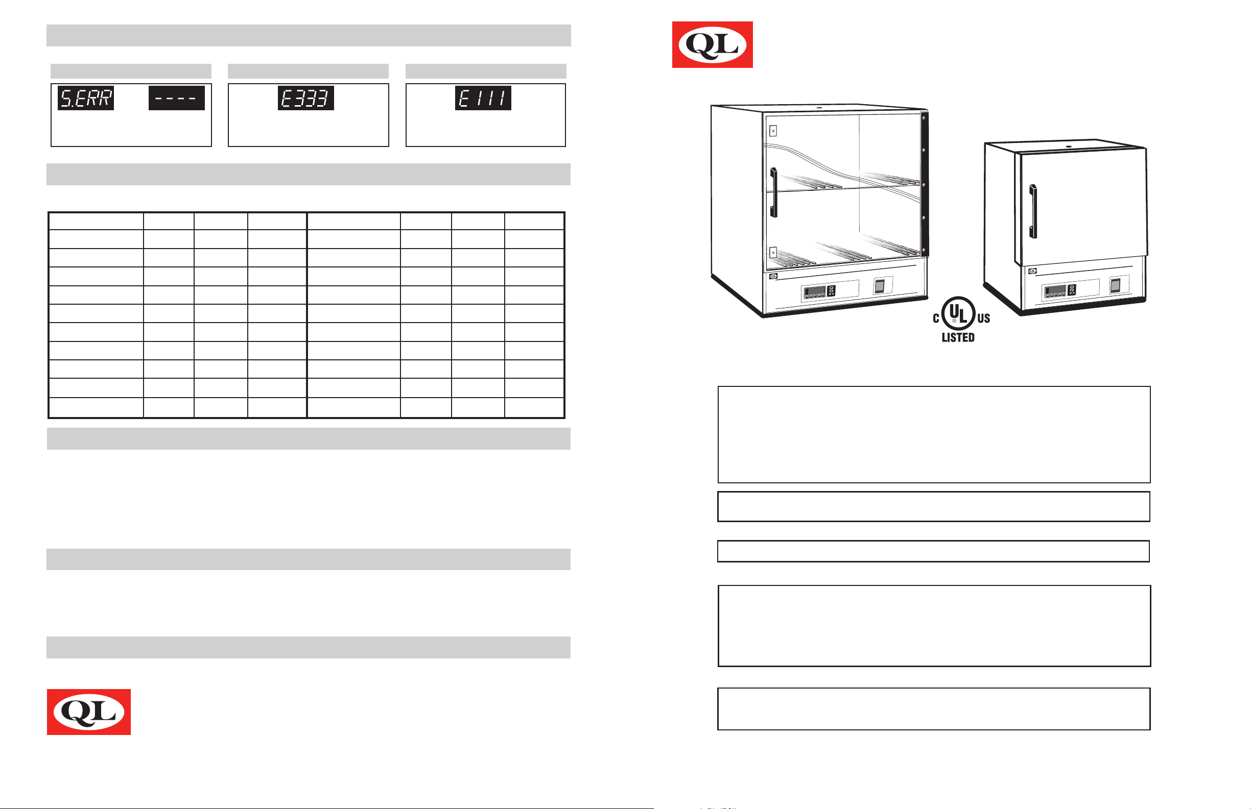
When the oven exceeds its maximum operating temperature by 3°C a safety alarm in the
controller will cut power to the heating elements. Allow the units temperature to drop
below its maximum temperature and/or cool before reset. To reset unit, power OFF and ON
to clear alarm status. If problem remains, please contact technical support for assistance.
ALARM “Over Maximum Temperature”
 










PAGE 3PAGE 2
Returning to Main Display and Clearing Controller Safety Alarm

This manual suits for next models

5

Other Quincy lab Accessories manuals

Quincy lab 140 Series User manual

Quincy lab

Quincy lab 140 Series User manual

Quincy lab 140E Series User manual

Quincy lab

Quincy lab 140E Series User manual

Quincy lab Digital Series User manual

Quincy lab

Quincy lab Digital Series User manual

Quincy lab 140AE-1 User manual

Quincy lab

Quincy lab 140AE-1 User manual

Quincy lab 140AE Series User manual

Quincy lab

Quincy lab 140AE Series User manual

Popular Accessories manuals by other brands

Clas Ohlson 98202 GB BS instruction manual

Clas Ohlson

Clas Ohlson 98202 GB BS instruction manual

Recon MOD Live user guide

Recon

Recon MOD Live user guide

CAS NT-302A manual

CAS

CAS NT-302A manual

LCT Eyegaze Edge user manual

LCT

LCT Eyegaze Edge user manual

Cardinal 185 Installation and technical manual

Cardinal

Cardinal 185 Installation and technical manual

PCB Piezotronics 117B66 Installation and operating manual

PCB Piezotronics

PCB Piezotronics 117B66 Installation and operating manual

Grizzly T10113 instruction manual

Grizzly

Grizzly T10113 instruction manual

Visonic MCT-320 SMA installation instructions

Visonic

Visonic MCT-320 SMA installation instructions

Labnet VorTemp 56 instruction manual

Labnet

Labnet VorTemp 56 instruction manual

UPPAbaby Upper Adapters quick start guide

UPPAbaby

UPPAbaby Upper Adapters quick start guide

PASCO PS-3215 Product guide

PASCO

PASCO PS-3215 Product guide

PCB Piezotronics PCB-(M)353B17 Installation and operating manual

PCB Piezotronics

PCB Piezotronics PCB-(M)353B17 Installation and operating manual

PCB Piezotronics 4115K-11A Installation and operating manual

PCB Piezotronics

PCB Piezotronics 4115K-11A Installation and operating manual

Banner iVu Plus TG Series instruction manual

Banner

Banner iVu Plus TG Series instruction manual

Pfeiffer Vacuum RPT 010 operating instructions

Pfeiffer Vacuum

Pfeiffer Vacuum RPT 010 operating instructions

Sparehand Systems Glacik G-505 quick guide

Sparehand Systems

Sparehand Systems Glacik G-505 quick guide

Bernard Liners SPEC L-1.2 Specification sheet

Bernard

Bernard Liners SPEC L-1.2 Specification sheet

ipf electronic UT300025 manual

ipf electronic

ipf electronic UT300025 manual

manuals.online logo
manuals.online logoBrands
  • About & Mission
  • Contact us
  • Privacy Policy
  • Terms and Conditions

Copyright 2025 Manuals.Online. All Rights Reserved.