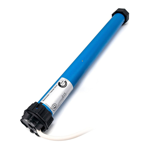
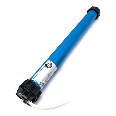
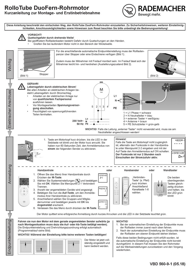
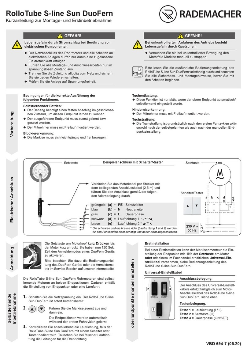
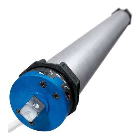
RADEMACHER RolloTube CLIS User manual

VBD 671-02(01.23)
Applicable for the following series: RolloTube C-line Small (CLIS) /Medium (CLIM)
Item numbers: 2240 06 56 / 2240 10 56 / 2260 10 56 / 2260 20 56 / 2260 30 56 / 2260 40 56 / 2260 50 56
Please note:
Site of installation:
..................................................................................................................
Serial number:
..................................................................................................................
RolloTube C-line Tubular Motors
Translation of the Original Operating and Assembly Manual
EN

2
EN
Contents
1. This manual... ..............................................3
2. Hazard symbols...........................................3
2.1 Levels of danger and signal words........3
2.2 Symbols and depictions used .................3
3. Safety instructions ......................................4
3.1 Intended use / operational
conditions....................................................... 5
3.2 Improper use................................................. 5
3.3 Required expert knowledge of the
installer............................................................ 5
3.4 Glossary - Definition ...................................6
4. Scope of delivery for RolloTube C-line
Small/Medium .............................................7
5. General view of the RolloTube C-line for
Small/Medium .............................................8
6. Functional description................................9
6.1 Blockage detection function................... 9
7. Important assembly instructions ............10
7.1 Installation of the tubular motor..........10
7.2 Mounting the bearings............................11
7.3 Determining the length of the
winding shaft (5) ........................................11
7.4 Mounting / dismantling the
adapter (10)..................................................12
7.5 Mounting /dismantling the drive
adapter (8)....................................................12
7.6 Sliding the tubular motor (9) into
the winding shaft.......................................13
7.7 Preparation for use of the precision
tubes ..............................................................13
7.8 Mounting the roller capsule (4)............15
7.9 Mounting the motor into the
bearing ..........................................................15
7.9.1 Mounting into the drive bearing
as a click bearing (13)...................15
7.9.2 Mounting in other drive bearing
versions.............................................15
7.9.3 Mounting into the counter
bearing (1)........................................16
7.10 Mounting the roller shutter (17)...........16
7.10.1Mounting the roller shutter
with rigid shaft connectors........16
8. Safety information regarding the
electrical connection.................................18
8.1 Connecting the motor cable (15).........18
8.2 Electrical connection of the tubular
motor .............................................................19
8.2.1 Control of a drive from a
single point with a
1-pole switch / button.................19
8.2.2 Parallel connection of several
motors ...............................................19
8.3 Connection of the universal setting
cable for manual end point setting.....20
8.4 Connecting a cord-switch setting
unit for manual end point setting .......20
9. Self-learning mode with soft stop ...........21
10. Manual adjustment of end points ...........21
10.1 Test run / modifying the end points.....23
11. Loading factory settings during the
commissioning process ............................23
12. What to do if... ?.........................................24
13. Technical specifications ............................25
14. Configuration of KNX/EIB Venetian blind
actuators for RADEMACHER tubular
motors........................................................25
15. Simplified EU declaration of
conformity .................................................26
i

3
EN
i
i
2. Hazard symbols
The following hazard symbols are used in this
instruction manual: Danger of fatal electric shock
Danger area / dangerous situation
2.1 Levels of danger and signal words
DANGER!
This hazard will lead to serious injury or death if not
avoided.
WARNING!WARNING!
This hazard may result in serious injury or death if
not avoided.
CAUTION!
This hazard may result in minor or moderate injury
if not avoided.
ATTENTION!
This hazard may lead to property damage.
2.2 Symbols and depictions used
Depiction / Description
1. Steps to be taken
2.
◆Itemisation
(1) List
iFurther useful
information
Please read the
respective manual
Unauthorised handling
or configuration
i
1. This manual...
◆...serves to describe the installation, electrical
connection and operation of RADEMACHER
tubular motors of the RolloTube C-line Small
and Medium series.
◆Before you begin, please read this manual
through completely and follow all the safety
instructions and assembly instructions.
◆This manual forms a component of the product.
Please store the manual in an easily accessible
place.
◆When passing the tubular motor on to any
future owners, this manual must be passed on
as well.
◆Damage resulting from non-compliance with
these instructions and safety instructions will
void the warranty. We assume no liability for any
consequential damage.
i

4
EN
3. Safety instructions
Risk of fatal electric shock when
touching electrical components.
◆The electrical connection for the tubular motor
and all work on the electrical systems may only be
undertaken by an authorised qualified electrician
and in accordance with the connection diagrams
in these instructions, see page 18 / 19 et seq.
◆Carry out all installation and connection work only
in an isolated, de-energised state.
Risk of fatal electric shock when
installed incorrectly in damp rooms.
◆Especially observe DIN VDE 0100, parts 701 and
702 when installing in damp rooms. These regu-
lations contain mandatory protective measures.
The use of defective equipment can lead to per-
sonal injury and damage to property (electric
shocks, short circuiting).
◆Never use defective or damaged equipment.
◆Check the drive and mains cable beforehand for
damage.
◆Should you discover damage to the equipment,
please consult our customer service department.
According to DIN EN 13659, it is necessary to deter-
mine that the movement conditions for the shutters
are maintained in accordance with EN 12045.
◆The displacement must be of at least 40 mm on
the lower edge in the rolled-out position with a
force of 150 N in the upwards direction.
◆In doing so, it must be ensured that the extend-
ing speed of the shutters for the final 0.4 m is less
than 0.15 m/s.
There is also a risk of fatal injury from crush-
ing resulting from uncontrolled starting of the
drive.
◆Never attempt to manually stop the motor/shut-
ters in the event of uncontrolled movement.
◆In such cases, switch off all power to the drive and
take appropriate safety precautions to prevent
unintentional switching on.
◆Arrange to have the system checked by a skilled
electrician.
Exceeding the maximum permissible running
time (KB = transient operation) may overload the
tubular motor.
◆The maximum permissible running time for a cycle
may not be exceeded when the equipment is in
operation. For this reason, the tubular motor has
a running time limit (KB = transient operation) of
four minutes.
◆If the running time limit is triggered, then the
tubular motor must be left for at least 20 minutes
to cool down.
Incorrect use leads to an increased risk of injury.
◆Train all personnel to safely use the tubular motor.
◆Do not allow children to play with the fixed
controllers and keep remote controls away from
children.
◆Cleaning and user maintenance may not be
carried out by children without supervision.
For roller shutters:
◆Watch the roller shutter whilst carrying out the
settings and keep other people away from the area
to avoid injury in the event of sudden slippage of
the shutter.
◆Watch the moving roller shutter during operation
and keep other people away from the area until
the movement has been completed.
◆Carry out all cleaning work on the roller shutter
whilst the device is disconnected from the mains
power.
For awning systems which can be operated out of
sight of the operator:
◆The awning may not be operated if work is being
carried out nearby (e.g. windows being cleaned).
For automatically actuated awnings:
◆Disconnect the awning from the power supply if
work is being carried out nearby.
A lack of maintenance can lead to personal injury
through damage to your tubular motor and roller
shutter or awning system:
◆Please check all of your roller shutter system
components regularly for damage.
◆Check regularly that the roller shutter system is
functioning correctly.
◆The shutters must not be damaged.
◆Damaged components should be exchanged by
a specialist roller shutter firm.
With awning systems:
◆Check the awning regularly for poor balance or
damaged lines and springs.
◆Have damaged awnings repaired by a specialist
awning firm.
Contact with the drive housing can cause burns.
◆The tubular motor gets hot during operation. Al-
low the motor to cool down prior to undertaking
any further work on the motor.
◆Never touch the hot drive housing.
5
EN
3.1 Intended use / operational conditions
Only use the tubular motors for opening and closing
standard flat roller shutters and awnings.
The use of the wrong tubular motors or compo-
nents can lead to property damage.
◆The motor cable must therefore be fitted with a
suitable empty tube up to the respective junction
box under observation of local electrical regula-
tions, if installed outside.
◆Only use the manufacturer’s original parts and
accessories.
◆Only use tubular motors which correspond to
the local conditions in terms of their power.
Incorrectly dimensioned tubular motors can lead
to damage:
> An insufficiently dimensioned tubular motor
can be damaged due to overloading.
> An excessively dimensioned tubular motor
can,
for example, cause damage to the roller shut-
ter or roller shutter box in self-learning mode.
◆Consult a specialist dealer when selecting a
tubular motor and observe the corresponding
tractive force specifications on our website:
www.rademacher.de
Operating conditions
◆A 230 V / 50 Hz power supply, together with a
site-provided isolating device (fuse) must be per-
manently available for the electrical connection at
the installation location.
◆The roller shutter must run up and down smoothly.
It should not jam.
Operational conditions for the self-learning
mode and for the correct functioning of the
blockage detection.
◆The roller shutter must be mounted to the wind-
ing shaft with rigid shaft connectors (6), see page
16.
◆The roller shutter must be fitted with stoppers or
an end-rail, see page 16.
3.2 Improper use
Using the RolloTube C-line for purposes other than
previously mentioned is impermissible.
Never use the tubular motor in systems with in-
creased safety-relevant requirements or where
there is an increased risk of accidents.
◆Such applications require additional safety equip-
ment. Observe the respective statutory regulations
for the installation of such systems.
Never use the tubular motor in continuous opera-
tion. Doing so will cause serious damage.
Never use the tubular motor for shutters with
openings of ≥ 50 mm in diameter.
3.3 Required expert knowledge of the installer
The installation, electrical connection and main-
tenance must be carried out by a qualified person
with appropriate training or by a specialist roller
shutter firm in accordance with the instructions in
this manual.
i
i
i

6
EN
3.4 Glossary - Definition
Blind
Roller shutter / Venetian blind or similar.
Blockage detection
The blockage detection is a safety function. The
tubular motor stops if the roller shutter is blocked.
DIN EN 13659
"Shutters and external Venetian blinds - Performance
requirements including safety."
This standard determines the performance require-
ments that externally attached shutters and blinds
must fulfil. It also contains significant hazards with
regard to the design, transportation, installation,
operation and maintenance of these shutters and
blinds.
DIN VDE 0100, Part 701 and 702
“Erection of low voltage installations -
Part 7-701 and 7-702“
This standard defines the requirements for special
installations or locations, rooms with a bath or
shower / basin etc.
Torque monitoring
The torque monitoring protects the roller shutter
and the complete system from being destroyed and
people from being injured. It is also used to find the
end points, amongst other things.
End points
An end point is defined and set for each direction
of travel of the roller shutter. Once this point has
been reached, the tubular motor switches off and
the roller shutter stops.
Transient operation (KB)
Tubular motors are not designed for continuous
operation. Transient operation defines the maxi-
mum permissible running time.
Magnetic ring
The magnetic ring (18) is located in the drive head
area (12). It is driven by the winding shaft (5) and the
adapter (10) and is used to find the end points, and
monitor/control the shaft rotations in normal mode.
Configuration of KNX/EIB Venetian blind
actuators
◆KNX/EIB Venetian blind actuators are used to
control electrically operatedVenetian blinds, roller
shutters etc.
◆Some parameters must be configured prior to
commissioning in order to ensure trouble-free
operation.
Roller shutter box
The tubular motor is installed in an existing or
retrofitted roller shutter box above the window.
Cord-switch setting unit
RADEMACHER accessory for the specialist roller
shutter firm to set the end points.
Rigid shaft connector
Assembly aid to fasten the roller shutter to the
winding shaft. A distinction is made between rigid
shaft connectors or anti-raise mechanisms and
flexible ties (made from metal).
i

7
EN
1a) c)
d) e)
b)
4. Scope of delivery for RolloTube C-line Small/Medium
Included in delivery
RolloTube C-line Small Medium
(a) Tubular motor, including connecting cable (2,5 m) 1 x 1 x
(b) Adapter
(c) Drive adapter, incl. retaining clip 1 x 1 x
(d) Click universal drive bearing 1 x -
(e) Click ready box support - 1 x
Please note:
Customer-specific scope of delivery
After unpacking please check the following:
Check that the package contents matches the scope of delivery listed on the package.
Check the details on the type plate
◆Check the details for the motor type.
◆Check that the voltage / frequency corresponds to the local
mains conditions.
i

8
EN
(16)
(17)
(1) (2) (4) (5) (6) (9) (10) (12)
(13)
(3) (11)
(14)
(15)
(8)(7)
2
5. General view of the RolloTube C-line for Small/Medium
Key to the overall view
(1) Counter bearing *
(2) Ball bearing *
(3) Axle pin on roller capsule *
(4) Roller capsule *
(5) Winding shaft *
(6) Rigid shaft connector *
(7) Retaining clip *
(8) Drive adapter *
(9) Tubular motor
(10) Adapter *
(11) Set button
(12) Drive head
(13) Click drive bearing *
(14) Retaining spring *
(15) Motor cable
(16) Controller (z.B. Troll Comfort) *
(17) Roller shutter
* The necessary accessories and all tubular motor controllers for this type of tubular motor incl. the
technical information and manuals can be found on our website.
www.rademacher.de
i

9
EN
6. Functional description
The RADEMACHER RolloTube C-line series of tubular
motors are designed for opening and closing roller
shutters and awnings.
The RolloTube C-line tubular motors are self-learning
motors with a soft stop at both end positions.The end
positions for the soft stop are automatically learned
during the first drive cycles.This eliminates the need
to set the end points or a learning cycle.
However of course, the end points can also be set
manually, see page 21.
The lower end point must be set manually when
using it as an awning drive, see page 21.
The compact design and self-learning soft stop
ensure a quick and easy installation.
The RolloTube C-line impresses in daily operation
with blockage detection in both directions of travel,
ensuring maximum safety and gentle operation.
iThe roller shutter must be equipped
with rigid shaft connectors and stoppers
in order to use the RolloTube C-line in
self-learning mode, see page 16.
Overview of functions:
◆Self-learning mode with a soft stop at both end
positions, see page 21.
◆Torque monitoring
◆Blockage detection in both directions of travel
◆Quick and easy installation thanks to the short
design
◆Either one or both end points can be set manu-
ally as required. Also in combination with the
self-learning mode.
6.1 Blockage detection function
The tubular motor stops in the event that the roller
shutter is blocked by an obstacle in one of the two
directions of travel (e.g. if a roller shutter is iced-up/
jammed).
Moving a blocked (e.g. iced-up/jammed) roller
shutter may overload and damage the tubular
motor and roller shutter system.
◆Do not move the iced-up/jammed roller shutter
and rectify the fault or remove the obstacle.
Requirements for correct blockage detection:
◆The roller shutter must be mounted to the wind-
ing shaft with rigid shaft connectors.
◆The roller shutter must always run vertically, eas-
ily and freely in the guide rails of the window.
i
i

10
EN
7. Important assembly instructions
Preparation for installation
◆Check that the voltage / frequency on the type
plate corresponds to local mains conditions prior
to installation.
◆You must remove or deactivate all cables and
equipment not required for operation of the
equipment prior to installation of the tubular
motor.
◆Moving drive parts to be operated at a height
under 2.5 m from the floor must be protected.
◆If the tubular motor is to be controlled with a
switch with a default OFF setting, then the switch
is to be positioned in the line of sight of the tubular
motor and at a height of at least 1.5 m.
◆The cover of the roller shutter box must be freely
accessible and removable without damaging it.
◆Never dismantle the stoppers from the final
roller shutter slat.
Otherwise the roller shutter may slip through
into the roller shutter box and be damaged.
Risk of fatal injury from crushing in the event of
operation without configured end points.
◆The end points must be configured in order to
ensure safe operation. In order to do so, please
refer to the corresponding chapter in this manual
on page 21.
The following installation instructions apply to
standard installation situations in combination with
RADEMACHER tubular motors and accessories.
The drive head (12) of the motor can be installed
on either the right or left side of the roller shutter
box.These instructions depict the installation on the
right-hand side.
7.1 Installation of the tubular motor
Required minimum width for the roller shutter
box:
Installing the tubular motor at an angle can cause
the tubular motor or roller shutter to be damaged.
For example, a roller shutter wound at an angle
can block the drive and cause damage.
◆Always ensure that the tubular motors and bear-
ings are mounted horizontally.
◆Please ensure that the winding shaft (5) and the
roller shutter (17) can move down easily and freely
after installation is complete.
◆The roller shutter (17) may not run over the bear-
ing, the roller capsule (4) or the drive head (12)
during operation.
◆Ensure that the winding shaft (5) and the rigid
shaft connectors (6) do not touch the drive (9).
They may not rub against the tubular motor (9)
during operation.
Tubular motor
type: Small Medium
Minimum width
approx.: 56 cm 67 cm
Incorrect installation can lead to injuries
(impact injuries and contusions).
◆The motor can eject from the drive bearing in the
event of incorrect installation/fastening. Fasten the
tubular motor with the securing devices provided.
For automatically actuated awnings:
◆A minimum gap of 0.4 m to other parts in the
area must be maintained when the awning is fully
extended.
◆Awnings used in an awning system must maintain
a minimum height of 1.8 m.
Incorrectly dimensioned drives and counter
bearings can cause the roller shutter system to
be damaged.
◆Only use original bearings supplied by the manu-
facturer. Third-party drives and counter bearings
must be selected in accordance with the torque
specifications of the respective tubular motors.

11
EN
BC
A
L
L = A - (B + C)
4
C
B
3
= (D/2)
7.2 Mounting the bearings
ATTENTION!
A roller shutter wound at an angle can block the
drive and cause damage.
◆Always ensure that the bearings are mounted as
horizontal as possible.
7.3 Determining the length of the winding shaft (5)
1. Measure the wall gap of the drive (13) and counter
bearing (1) as shown.
2. Measure the roller shutter box and calculate the
required shaft length [ L ].
3. Length of the winding shaft: L = A - (B + C).
Recommendation
Shorten Lby approx. 5 mm more than calculated
by the equation to ensure a sufficiently large space
of 2 to 3 mm in the overall length when the roller
capsule (4) is inserted.
4. Shorten the winding shaft (5) to the required size.
Cut the shaft to size with a hacksaw at a right-angle.
Remove the burrs from the shaft internally and ex-
ternally with a file.
1. First determine the position of the drive (13) and
counter bearing (1) in the roller shutter box.
2. Wind the roller shutter casing fully onto the winding
shaft and measure the diameter [ D ]. See figure [ 3 ]
for determining the position of the centre of the
bearing to the guide rail.
iWhen installed, the wound roller shutter
must run vertically in the guide rail on the
window.
3. Fasten the bearing in accordance with the bearing
type and on-site conditions.
4. Mount the drive bearing (13) so that the set button
(11) on the drive head will be easily accessible at
a later stage and the motor cable (15) can be laid
without kinking.
B= Counter bearing / roller capsule
C= Drive bearing / motor

12
EN
(10)
(18)
5
6
(8) (19)
(7)
7
8
(7)
7.4 Mounting / dismantling the adapter (10)
Mounting the adapter (10)
1. Slide the adapter (10) over the magnetic ring (18)
on the drive head until it engages. In doing so, check
the correct positioning of the groove in the adapter
(10) (original factory settings).
Dismantling the adapter (10)
1. Press the two retaining springs on the magnetic ring
(18) downwards and pull the adapter (10) off the
magnetic ring (18).
Press the re-
taining springs
downwards.
7.5 Mounting /dismantling the drive adapter (8)
Dismantling the drive adapter (8)
1. Release the retaining clip (7) from the gear drive shaft
(19) and pull the drive adapter (8) off again.
Mounting / dismantling the drive adapter (8)
1. Slide the drive adapter (8) onto the gear drive shaft
(19) until it can go no further and secure it with the
retaining clip provided (7) (original factory settings).

13
EN
(10)
11
(8)
(9)
(5)
9
10
1. Measure the distance between the adapter (10) and
the rear third of the drive adapter (8) and mark this
distance on the precision tube.
iPlease only use precision
tubes made from aluminium.
◆The following steps can be left out
when using octagonal steel shafts.
ALUMINIUM
7.7 Preparation for use of the precision tubes
7.6 Sliding the tubular motor (9) into the winding shaft
ATTENTION!
Inserting the tubular motor
(9) forcibly into the winding
shaft (5) will cause serious
damage.
◆Never knock the tubular
motor (9) with force into
the winding shaft (5).
1. First slide the drive adapter (8) into the winding
shaft (5).
iThe motor (9) must have sufficient free
space for winding shafts with internal felt.
2. Subsequently, press the winding shaft (5) fully
onto the adapter (10).
ATTENTION!
◆In doing so, ensure that the adapter (10) does
not slip off the magnetic ring (18) on the drive
head (12) during the assembly process. Other-
wise malfunctions may occur, see page 24.
◆The motor must always be pushed fully into
the winding shaft. The length compensation or
correction is configured with the position of the
roller capsule, see page 16.

14
EN
1
13
12
14
15
16
1
RolloTube C-line Small
RolloTube C-line Medium
2. Saw a groove in the end of the precision tube 1
in order that the cam of the adapter (10) can
be completely pressed into the tube.
7.7 Preparation for use of the precision tubes
◆There may not be any play between the groove
1and the cam .
◆The dimensions for the groove 1 are depend-
ent on the tubular motor type used, see figures.
3. Slide the tubular motor into the precision tube.
4. Mark the four fastening holes and subsequently
drill them through the precision tube into the drive
adapter (8).
◆Never drill deeper than 10 mm into
drive adapter (8).
ATTENTION!
Drilling in the area of the drive causes serious
damage.
◆Never drill in the area of the drive (9).
5. Screw or rivet the precision tube to the drive
adapter (8).
Use four self-tapping sheet metal screws or four
pop rivets for this.

15
EN
(11) (12) (13) (14)
18
(2)
(3)
(4) (5)
17
7.8 Mounting the roller capsule (4)
1. Slide the roller capsule (4) into the winding shaft (5)
and subsequently place the ball bearing (2) onto the
axle pin (3) of the roller capsule.
7.9 Mounting the motor into the bearing
iThe tubular motors can be fitted into the
click bearing (13) in 4 positions.
◆The motors can be released from the
click bearing (13) at any time by means
of expanding the retaining spring (14).
7.9.1 Mounting into the drive bearing as a click bearing (13)
1. Press the drive head (12) lightly into the click bear-
ing (13) until it engages. The set button (11) must
be easily accessible.
Hook the drive head (12) into the corresponding
drive bearing and secure, for example, with a cotter
pin.
7.9.2 Mounting in other drive bearing versions
WARNING!WARNING!
Risk of short-circuit resulting from water in the
event of improper cabling.
◆Never lay the motor cable (15) vertically upwards
otherwise water may collect on the cable and run
into the motor, leading to damage.
◆Lay the cable in a loop. The loop will cause any
water on the cable to collect at the lowest point,
from where it can drain off.

16
EN
(5)(4)
(1)
(2)
19
7.10 Mounting the roller shutter (17)
ATTENTION!
Drilling and inserting
screws in the area of the
drive will cause the drive
to be damaged.
◆Never drill or insert screws in the area of the drive
(9) in order to secure the roller shutter (17).
ATTENTION!
The roller shutter may run into the roller shutter
box in self-learning mode and be damaged with-
out rigid shaft connectors and stoppers.
◆Connect the roller shutter (17) to the winding
shaft (5) with rigid shaft connectors (6).
◆Always fit two stoppers or an
end-rail to the roller shutter (17).
7.9.3 Mounting into the counter bearing (1)
1. Insert the other end of the winding shaft (5) with the
ball bearing (2) into the counter bearing (1).
2. In the event that you are using a different bearing
than the RADEMACHER click bearing (13), you may
need to secure the drive with a secondary cotter pin.
3. Correct any slight inaccuracies in size by means of
sliding the roller capsule (4) in or out.
iThe roller capsule (4) must be inserted at
least 2/3 of its length into the winding
shaft (5).
Make sure that there is sufficient space in
the axle length to ensure ease of move-
ment.
4. Finally, secure the roller capsule (4) with a screw.
7.9 Mounting the motor into the bearing
7.10.1 Mounting the roller shutter with rigid shaft connectors
Determine the number of rigid shaft connectors required
iMount at least two rigid shaft connectors per roller shutter on both ends of the corresponding octagonal
shaft. The number of rigid shaft connectors may vary from the following recommendation, depending on
the operating conditions.
Roller shutters width / minimum number:
Recommendation: Mount an additional rigid shaft connector every 800 mm.
800 mm 800 mm 800 mm
(1410 mm - 2350 mm)
(4 x )
(3 x )
(2350 mm - 3300 mm)
(3 x )
0 mm - 1400 mm (2 x )

17
EN
(20)
(17)
22
20
21
(6)
(5)
(17)
1. Mount the shaft connectors (6) at the winding
shaft (5).
In order to do so, follow the information provided in
the operating manual for shaft connectors.
4. Finally, mount two roller shutter stoppers (20) or
an end-rail onto the lowermost slat or rail of the
roller shutter (17).
2. Slide the retainer profile for each shaft connector (6)
onto the uppermost slat of the roller shutter (17).
3. Subsequently slide each retainer profile over a
shaft connector (6).
7.10 Mounting the roller shutter (17)

18
EN
(11)
L1
L1
N
PE
(15)
(*)
23
DANGER!
Risk of fatal electric shock when
touching electrical components.
◆Carry out all installation and connection work only
in an isolated, de-energised state.
◆Disconnect all phases of the mains power cable
and secure it to prevent any reconnection.
◆Check that the system is de-energised.
WARNING!WARNING!
Risk of short-circuit resulting from water in the
event of improper cabling.
◆Never lay the motor cable (15) vertically upwards
otherwise water may collect on the cable and run
into the motor, leading to damage.
◆Lay the cable in a loop. The loop will cause any
water on the cable to collect at the lowest point,
from where it can drain off.
8. Safety information regarding the electrical connection
WARNING!WARNING!
Risk of short-circuit resulting from damaged
cable.
◆Lay all cables in the roller shutter box so that they
cannot be damaged by moving machinery.
◆The mains connection for the drive may only be
connected with the same conduction type. Con-
sult customer services if necessary.
Fixed-installation devices...
...must be equipped on the installation side with a
circuit-breaker for each phase in accordance with
DIN VDE 0700. Switches with a contact opening
width of min. 3 mm can be used as circuit-breakers
(e.g. power switch, power circuit breaker or residual-
current-operated circuit-breaker).
8.1 Connecting the motor cable (15)
1. Connect the motor cable (15) according to the fol-
lowing wiring configuration.
Colour scale for the motor leads (15)
L1 = (black) *
L1 = (brown) *
N= neutral terminal (blue)
PE = earth (green / yellow)
(11) = Set button on tubular motor
i* The actual direction of travel of the
tubular motor and the roller shutter
depends on the direction of installa-
tion and the wiring of the tubular
motor. * The grey wire has no function and should be connected
to the neutral terminal.

19
EN
L1
N
PE
4
3
24 (a)
(b)
(c)
(d)
(e) (f) (g)
(h) (i)
4
4
3
4 4
4 4
25
(a)
(b)
(c)
Legend
(a) = Set button (11)
(b) = Controller (e.g. 1-pole switch / button)
(c) = Mains 230 V/50 Hz
(d)= Socket box
Pin assignment
(e) =PE green / yellow
(f) = Nblue
(g) = L1 black
(h) = black (direction of travel 1)
(i) = brown (direction of travel 2)
* The grey wire has no function and should be connected
to the neutral terminal.
8.2.1 Control of a drive from a single point with a 1-pole switch / button
8.2.2 Parallel connection of several motors
It is possible to connect numerous RADEMACHER
tubular motors in parallel. The number of motors to
be connected in parallel is dependent on the capacity
of the switchgear and circuit-breakers.
iIt is not possible to control individual
motors if the equipment is connected in
parallel.
8.2 Electrical connection of the tubular motor
End point setting of tubular motors connected
in parallel:
◆RolloTube C-line in self-learning mode:
> No end point setting is required,
see page 21.
> Manual adjustment of the lower end point is
required when using as an awning drive, see
page 21.
◆RolloTube C-line in parallel connection with
other tubular motors:
> The end points must be set for each other
tubular motor in accordance with the respec-
tive operating manual.
Using rigid shaft connectors and stoppers
RolloTube C-line in self-learning mode and tubular
motors with automatic end point setting must be
fitted with rigid shaft connectors and stoppers, see
also page 16 and 21.
Parallel connection with Venetian blind switch-
es or Venetian blind buttons
UP to five motors can be switched in parallel with
RADEMACHER Venetian blind switches or Venetian
blind buttons.
Parallel connection with RADEMACHER control-
lers (e.g. Troll Comfort)
Please refer to the technical data for the respective
number of tubular motors that can be connected
in parallel.
iWhen using a switch, we recommend that the mains power to the motor is switched off (switch in zero position)
after reaching the end points. This avoids the motor experiencing sources of interference or excess voltages.
Installation example
Legend
(a) = Junction box
(b) = Controller, e.g. 1-pole switch / button
(c) = Mains 230 V / 50 Hz

20
EN
27
(21)
26
8.4 Connecting a cord-switch setting unit for manual end point setting
1. Open the terminal contacts by pressing the plung-
ers and connect all of the wires of the motor cable
(15) corresponding to their functions, see also
figure [ 23 ].
Pin assignment:
SET
Motor cable (15) > cord-switch
setting unit
L1 (black) > ON (black)
L1 (brown) > SET (white)
NNeutral terminal (blue) > N(blue)
PE Earth (green/yellow) > PE (green/yellow)
= direction of travel 1
= direction of travel 2
= no function
ON
8.3 Connection of the universal setting cable for manual
end point setting
1. Open the terminal contacts by pressing the plung-
ers and connect all of the wires of the motor cable
(15) with the same colours and corresponding to
their functions, see also figure [ 23 ].
Pin assignment:
The connection is made with the same colours as the
motor connecting cable of the RolloTube C-line, see
figure [ 23 ].
Button assignment for RolloTube C-line:
Button 1 = direction of travel 1 / 2
Button 2 = set button
Button 3 = no function
Button 1
Button 2 Button 3
This manual suits for next models
8
Table of contents
Other RADEMACHER Engine manuals

RADEMACHER
RADEMACHER RolloTube S-line DuoFern Reference guide

RADEMACHER
RADEMACHER RTBS Product guide

RADEMACHER
RADEMACHER RolloTube Comfort 2360 20 80 User manual

RADEMACHER
RADEMACHER RolloTube S-line Sun DuoFern Reference guide

RADEMACHER
RADEMACHER RolloTube DuoFern Reference guide

RADEMACHER
RADEMACHER RolloTube Basic 2160 20 90 User manual

RADEMACHER
RADEMACHER RolloTube S Firmware update

RADEMACHER
RADEMACHER RooloTube S Sun DuoFern Medium Series Product guide

RADEMACHER
RADEMACHER RolloTube Comfort Small Series User manual

RADEMACHER
RADEMACHER RolloTube S-line DuoFern Reference guide