manuals.online logo
Brands
  1. Home
  2. •
  3. Brands
  4. •
  5. Radio Shack
  6. •
  7. Printer
  8. •
  9. Radio Shack DMP-200 User manual

Radio Shack DMP-200 User manual

SERVICE POLICY
Radio Shack's nationwide network of service facilities provides quick, convenient,
and reliable repair services for all of its computer products, in most instances.
Warranty service will be performed in accordance with Radio Shack's Limited
Warranty. Non-warranty service will be provided at reasonable parts and labor
costs.
Because of the sensitivity of computer equipment, and the problems which can
result from improper servicing, the following limitations also apply to the services
offered by Radio Shack:
1. If any of the warranty seals on any Radio Shack computer products are
broken, Radio Shack reserves the right to refuse to service the equipment or
to void any remaining warranty on the equipment.
2. If any Radio Shack computer equipment has been modified so that it is not
within manufacturer's specifications, including, but not limited to, the
installation of any non-Radio Shack parts, components, or replacement
boards, then Radio Shack reserves the right to refuse to service the
equipment, void any remaining warranty, remove and replace any non-Radio
Shack part found in the equipment, and perform whatever modifications are
necessary to return the equipment to original factory manufacturer's
specifications.
3. The cost for the labor and parts required to return the Radio Shack computer
equipment to original manufacturer's specifications will be charged to the
customer in addition to the norma! repair charge.
TERMS AND CONDITIONS OF SALE AND LICENSE OF RADIO SHACK COMPUTER EQUIPMENT AND SOFTWARE
PURCHASED FROM ARADIO SHACK COMPANY-OWNED COMPUTER CENTER. RETAIL STORE OR FROM A
RADIO SHACK FRANCHISEE OR DEALER AT ITS AUTHORIZED LOCATION
Jjj
CUSTOMER OBLIGATIONS LIMITED WARRANTY
IfeVs?:
US]
Ir
ACUSTOMER assumes full responsibility that this Radio Shack computer harcware purchased (the "Equipment"), and any copies of Radio
Shack software included with the Equipment or licensed separately (the •Software") meets the specifications, capacity, capabilities,
versatility, and other requirements of CUSTOMER
8CUSTOMER assumes full responsibility for the condition and effectiveness of the operating environment in which the Equipment and Software
are to function, and for its installation
II. RADIO SHACK LIMITED WARRANTIES AND CONDITIONS OF SALE
A. For aperiod of ninety (90) calendar days from the date of the Radio Shack sales document received upon purcnase of the Equipment. RADIO
SHACK warrants to the original CUSTOMER that the Equipment and the medium upon which the Software is stored is free from manufacturing
defects. THIS WARRANTY IS ONLY APPLICABLE TO PURCHASES OF RADIO SHACK EQUIPMENT BY THE ORIGINAL CUSTOMER FROM
RADIO SHACK COMPANY-OWNED COMPUTER CENTERS. RETAIL STORES AND FROM RADIO SHACK FRANCHISEES AND DEALERS AT ITS
AUTHORIZED LOCATION. The warranty is void if the Equipment's case or cabinet has been opened, or if the Equipment or Software fras fjserr
subjected to improper or abnormal use. If amanufacturing defect is discovered during the stated warranty period, the defective Equipment
must be returned to aRadio Shack Computer Center, aRadio Shack retail store, participating Radio Shack francnisee or Radio Shack dealer
for repair, along with acopy of the sales document or iease agreement. The original CUSTOMER'S sole and exclusive remedy in the event of
adefect is limited to the correction of the defect by repair, replacement, or refund of the purchase price, at RADIO SHACK'S election and scie
expense. RADIO SHACK has no obligation to replace or repair expendable items.
B. RADIO SHACK makes no warranty as to the design, capability, capacity, or suitability for use of the Software, except as provided in this
paragraph Software is licensed on an "AS IS" basis, without warranty. The original CUSTOMER'S exclusive remedy, in the event of a
Software manufacturing defect, is its repair or replacement within thirty (30) calendar days of the date of the Radio Shack sales document
received upon license of the Software. The defective Software shall be returned to aRadio Shack Computer Center, aRadio Shack retail store,
participating Radio Shack franchisee or Radio Shack dealer along with the saies document.
C. Except as provided herein no employee, agent, franchisee, dealer or other person is authorized to give any warranties of any nature on behalf
of RADIO SHACK
D. Except as provided herein. RADIO SHACK MAKES NO WARRANTIES. INCLUDING WARRANTIES OF MERCHANTABILITY OR FITNESS FOR A
PARTICULAR PURPOSE.
E. Some states do not allow limitations on how long an implied warranty lasts, so the above limitations) may not appiy to CUSTOMER.
III. LIMITATION OF LIABILITY
AEXCEPT AS PROVIDED HEREIN. RADIO SHACK SHALL HAVE NO LIABILITY OR RESPONSIBILITY TO CUSTOMER OR ANY OTHER PERSON
OR ENTITY WITH RESPECT TO ANY LIABILITY. LOSS OR OAMAGE CAUSED OR ALLEGED TO BE CAUSED DIRECTLY OR INDIRECTLY SY
"EQUIPMENT" OR "SOFTWARE" SOLD. LEASED. LICENSED OR FURNISHED BY RADIO SHACK, INCLUDING. BUT NOT LIMITED TO. ANY
INTERRUPTION OF SERVICE. LOSS OF BUSINESS OR ANTICIPATORY PROFITS OR CONSEQUENTIAL DAMAGES RESULTING FROM THE
USE OR OPERATION OF THE 'EQUIPMENT"" OR "SOFTWARE" IN NO EVENT SHALL RADIO SHACK BE LIABLE FOR LOSS OF PROFITS. OR
ANY INDIRECT. SPECIAL. OR CONSEQUENTIAL DAMAGES ARISING OUT OF ANY BREACH OF THIS WARRANTY OR IN ANY MANNER
ARISING OUT OF OR CONNECTED WITH THE SALE. LEASE. LICENSE. USE OR ANTICIPATED USE OF THE "EQUIPMENT" OR "SOFTWARE".
NOTWITHSTANDING THE ABOVE LIMITATIONS AND WARRANTIES, RADIO SHACK'S LIABILITY HEREUNDER FOR DAMAGES INCURRED BY
CUSTOMER OR OTHERS SHALL NOT EXCEED THE AMOUNT PAID BY CUSTOMER FOR THE PARTICULAR "EQUIPMENT" OR "SOFTWARE"
INVOLVED
B. RADIO SHACK shall not be liable for any damages caused by delay in delivering or furnishing Equipment and-or Software.
C. No action arising out of any claimed breach of this Warranty or transactions under this Warranty may be brought more than two (2) years
after the cause of action has accrued or more than four (4) years after the date of the Radio Shack sales document for the Equipment or
Software, whichever first occurs.
0. Some states do not allow the limitation or exclusion of incidental or consequential damages, so the above limitations) or exciusion(s) may
not apply to CUSTOMER.
IV. RADIO SHACK SOFTWARE LICENSE
RADIO SHACK grants to CUSTOMER anon-exclusive, paid-up license to use the RADIO SHACK Software on one computer, subject to the following
provisions:
A. Except as otherwise provided in this Software License, applicable copyright laws shall apply to the Software.
B. Title to the medium on which the Software is recorded (cassette and/or diskette) or stored (ROM) is transferred to CUSTOMER, but not title to
the Software.
C. CUSTOMER may use Software on one host computer and access that Software through one or more terminals if the Software permits this
function.
0. CUSTOMER shall not use. make, manufacture, or reprpduce copies of Software except for use on one computer and as is specifically
provided in this Software License. Customer is expressly prohibited from disassembling the Software.
E. CUSTOMER is permitted to make additional copies of the Software only for backup or archival purposes or if additional copies are required in
the operation of one computer with the Software, but only to the extent the Software allows abackup copy to be made. However, for
TRSDOS Software. CUSTOMER is permitted to make alimited number of additional copies for CUSTOMER'S own use. *
F. CUSTOMER may resell or distribute unmodified copies of the Software provided CUSTOMER has purchased one copy of the Software for each
one sold or distributed. The provisions of this Software License shall also be applicable to third parties receiving copies of the Software from
CUSTOMER.
All copyright notices shall be retained on all copies of the Software.
APPLICABILITY OF WARRANTY
A. The terms and conditions of this Warranty are applicable as between RADIO SHACK and CUSTOMER to either asale of the Equipment and/or
Software License to CUSTOMER or to atransaction whereby RADIO SHACK sells or conveys such Equipment to athird party for lease to
CUSTOMER.
The limitations of liability and Warranty provisions herein shall inure to the benefit of RADIO SHACK, the author, owner and/or licensor of the
Software and any manufacturer of the Equipment sold by RADIO SHACK.
The warranties granted herein give the original CUSTOMER specific legal rights, and the original CUSTOMER may have other rights which vary
from state to state.
Contents
Introduction 1
1/ Description of the DMP-200 3
Top Panel 4
Rear Panel .....5
2/ Setting Up the DMP-200 7
Tractor Installation and Removal *7
How Does the DMP-200 Handle Paper? 9
Paper Loading 9
Ribbon Installation/Replacement 13
Print Function (DIP) Switches 14
Setting the Rotary Switch 16
Connecting the DMP-200 to aPower Source 16
Carriage Movement Test 17
Self-Test 17
Connecting the DMP-200 to aTRS-80 17
Power-Up Sequence 18
3/ Using the DMP-200 (General Printed Operation). .... 19
Control Codes 19
Sending Control Codes from BASIC 20
Data Processing Mode 20
Word Processing Mode ... .
.
21
Graphics Mode 21
Selecting aPrint Mode 21
4/ Print Font Styles and Character Widths 23
Selecting Font Styles 24
Standard Character Font Style 24
Correspondence Quality Font Style 25
Proportional Spaced Font Style 25
Graphic Characters 25
Right Justification 26
Wrap-Around 27
Elongated Characters 27
Bold Characters 28
5/ General Control Codes 29
Line Feed (LF) 29
Carriage Return (CR) 30
Backspace (BS) 30
Setting Top-of-Form and Form Length 31
Form Feed (FF) 31
Ignored or Undefined Codes 31
DMP-200 Buffer Operation 32
6/ Word and Data Processing Modes . . ...35
Superscript and Subscript 35
Repeat Printing 35
Underline Printing 36
Print Head Positioning . . 36
7/ Graphics Mode 39
Printing Graphics Patterns 40
Line Feed 41
Repeat Function 41
Print Density 42
Leaving Graphics Mode 42
Mixing Modes 42
Free Hand Drawing 42
Appendix A/ Control Code Summary 45
Appendix B/ Character Sets 49
Appendix C/ Programming Information 55
Appendix D/ Care and Maintenance 57
DMP-200 Printing Limits (Duty Cycle) 59
Appendix E/ Specifications 61
Introduction
Congratulations for selecting this Radio Shack computer product! The DMP-200 is a
high-density dot-matrix printer which can perform avariety of different printing operations.
For instance, it can print:
•Proportional spaced characters.
•Monospaced characters (Normal, Condensed and Compressed).
•Correspondence Quality characters.
•Graphic characters.
For maximum efficiency ,the DMP-200 operates in three modes:
•Data Processing Mode for fastest output of program listings or data.
•Word Processing Mode for letter-writing or the creation of any text documentation
.
•GraphicsMode for drawing pictures, figures, or graphs.
For word-processing, you'll find the DMP-200's Proportional spaced characters (created on
avariable 15x9 dot-matrix) can produce letter-quality results.
If, however, you need aprint-out that is produced faster, Monospaced characters (created
on an 9x8dot-matrix) are just the thing for you!
In the Graphics Mode, you can use graphic data to draw just about any type of graphic
configuration you desire.
You can use three types of paper with the DMP-200.
•Standard (4"- 10" wide) computer fanfold forms with guide holes. The Printer can also
print one original and up to two carbon-copies
.
•Standard single-sheet typewriter paper for use as an ordinary typewriter.
•Roll paper (8 Vi wide) with a1" core and amaximum diameter of 5".
Other software-controlled features include:
•Bi-directional logic-seeking carriage motion, (uni-directional in Graphic Mode.)
•Full- or Half-Line Forward and Reverse (for printing above or below the *'current' 'line)
and 3/4 Line Feed.
•Underline capability.
•Paper Empty sensor automatically stops the printer so you can replenish the paper.
•Parallel and Serial Interfaces.
and much more
!
1/ Description ofthe DMP-200
Carefully unpack the DMP-200, being sure to locate the Ribbon Cassette, the Paper Tray,
the Roll Paper Holder and the Roll Paper Shaft. Keep the empty box and packing material
just in case you ever need to transport the Printer.
Be sure to remove theprotective blackplastic tubefrom the rear Carriage Guide.
Figure 1. Removing the Black Tube
It's important to become familiar with the DMP-200 before you set it up and begin using it.
Figure 2. DMP-200 (Top View)
^!?WE
:
R
J
0nin
udi^t0r-Th'SIndic3tor wiI1 i^minate when the DMP-^00 is properly
connected and the Power ON/OFF Switch is set to ON. -uu is properly
@i^RT IndicatCfThls lamPwiil »me on when the Printer is out ofpaper when
there is acarnage fault, or when there is some son of electrical problem.
@SSSSnt TES
,
WUCh*^^ SWkCh mUSt be S£t t0 0N"LINE bef0re «he
2JSS£SrHZpnntmg at anytime orto use otherFront Pane! Switches -
©RESTART Switch. When the Printer runs out of paper, pushing this switch resumes
IZl1^- ?eV!0p after comPleti ™another line printing or loading new paSrTen
presses Switch to return the Printer to its statufbefore the out-oKr'cSndition
®fhtswkch^nJenuhiS SWkCh iS pr£SSed 'the paper wil1 advance one line -Holdine
theSwitch down will cause cont.nuous paper feed. The Printer must be OFF-LINE
beforepressing this Switch.
®1™%°N/0FF SwitCh-Pr£SS the white dot t0 tum the P°w"ON.Press the Switch
the other way to turn power OFF. Note that turning the power OFF and ON durin*
operation may cause loss of the current program.
®Print Head Control Lever. Move this Levertowards you (e.g. .move the Print Head
away from the paper) when changing ribbons. If printing is faint, move the Lever away
ZZ^?•* '
*
eP™1"6*1towards the paper); if smudging occurs during printing,
move the Print Head slightly away from the paper
®Platen Pressure Lever. If you are "friction feeding" paper (single sheets or roll papaer),
position this lever toward the rear of the printer to apply pressure on the Platen. If
you are "tractor feeding" (fanfold), position this lever toward the front of the printer.
CD Paper Bail Lever. For optimum print quality ,keep the Bail down on the paper (Lever
toward rear of printer)
.
®Tractor Feed. See Setting Up the DMP-200 for derails on using the Tractor Feed.
©Paper Feed Knob. Turn this Knob to manually advance the paper.
©Paper Insertion Opening. Be sure the paper enters the DMP-200 here (just
underneath the black metal shield).
©Paper Guide Rack. Prop this rack up for single sheet paper feeding, down for fan fold
paper, and remove it for roll paper feeding.
When the Printer stops because it is out of paper, the ALERT lamp will illuminate, and the Printer
automatically goes OFF-LINE. To continue printing press RESTART, then printing will be done
one more line, or insert more paper and press RESTART. The DMP-200 will automatically go
back ON-LINE (and continue printing without loss of data in the print buffer).
Model II users :If aBASIC program stops execution because of aPrinter error, typing:
CDNT (ENTER) after you have put the printer back on-line will cause printing to resume.
However, the entire contents of the print buffer will be printed starting with the current Print
Head position.
®©©
Figure 3. DMP-200 (Rear View)
©Parallel Interface Connector. If your TRS-80 has parallel interface capabilities
,
connect the cable here.
®Serial Interface Connector. If your TRS-80 has serial interface capabilities, connect
the cable here. See Setting Up the DMP-200 for the correct cable for your TRS-80.
®Function Selection (DIP) Switch. The settings of this switch define the printer's use.
©Rotary Switch. This switch selects the character style to be used by the printer.
©Power Cord. Plug the power cord into awall-outlet or approved power strip.
2/ Setting Up the DMP-200
This section will show you how to set up the DMP-200 so you can begin using it as quickly
as possible. This includes:
•Loading paper.
•Replacing aribbon.
•Connecting the DMP-200 to aTRS-80
and more!
The following Start-Up Checklist is asummary of how to set up your Printer. You should
follow this procedure every time you start-up the Printer —notjust the first time.
Find agood spot for your Printer. Be sure to consider:
•The Printer should be placed on asturdy work surface.
•The length of the printer cable will determine how far from the TRS-80 you can place
the Printer.
•Papertakes up space. Be sure to leave enough room forsmooth paper flow.
•Don't place the Printer near noise generators such as refrigerators and industrial
equipment.
Be sure the POWER switch (at left side of Printer) is OFF.
Remove the Top Cover and the packing materials.
Install continuous form fanfold paper, single-sheet paper, or roll paper. Refer to Paper
Loading.
Check the Ribbon Cassette. If it has not been installed, see Ribbon
Installation/Replacement.
Set Front Panel Switches, Rotary Dial and Print Function (DIP) Switch (rear of Printer).
Connect the AC powerplug to a3-wire, 120 volt, 60 Hz grounded AC outlet (220/240v,
50 Hz where the unit is so marked).
Check that the Printer is ready by running the Self-Test.
Connect the interface cable from the TRS-80 to the printer interface connector.
Turn the Power ON and check that the Power On Indicator (on the Front Panel) is
illuminated.
Push the RESTART Switch.
Place ON-LINE/OFF-LINE Switch in ON-LINE position.
Tractor Installation and Removal
This printer can be used with either the Tractor Feed system or the Friction Feed system.
The difference is that the Tractor Feed system is used with paper which has guide holes on
both edges while the paper used with the Friction Feed system does not have these holes.
The Friction Feed system may be used with the tractor installed; however, better
operation can be acheived if it is removed especially with single sheets of paper.
Removing the Tractor
1. Set the ON/OFF Power Switch to OFF.
2. Remove the Top Cover.
3. Hold the back bar of the Tractor (close to the edges) between the thumb and forefinger of
each hand and pull upward to unlock and remove the tractor.
4. Replace the Top Cover.
Installing the Tractor
1. Set the ON/OFF Power Switch to OFF.
2. Remove the Top Cover.
3. Place the front cutouts in the Tractor unit onto the outside studs (see Figure 4), then press
on the rear of the Tractor until the back posts snap into place.
4. Replace the Top Cover.
Figure 4. Installing the Tractor
8
How Does the DMP-200 Handle Paper?
The DMP-200 provides both Tractor Feed for continuous forms and Friction Feed for
single-sheet printing.
Paper Loading
Warning! When loading paper (single-sheets, roll or fanfold) ,be sure the paper correctly
enters the Paper Insertion Opening.
If the paper is correctly loaded, it should enter between the body ofthe Printer and the
Paper Separator. Once the paper is loaded and power is ONrcheck the ALERT Indicator. If
the lamp is illuminated, press the RESTART Switch. If the lamp remains on, the paper is
probably loaded incorrectly
.
If the lamp is not illuminated after the paper is loaded, you mav besin printing (if the power
is ON). 'w
Single-Sheet Paper Loading
We suggest you remove the tractor feed unit before loading single-sheet
paper into the DMP-200.
1. Be sure the Power Switch is OFF.
2. Remove the Top Cover.
3. Gently move the Print Head Control Lever away from the paper.
4. Move the Platen Pressure Lever forward (toward the front of the Printer).
5
.
Insert the paper into the Paper Insertion Opening (underneath black shield) and push
the Release Lever back towards the rear of the Printer. Use the Paper Feed Knob to
advance the paper until it appears between the Platen and the Print Head. (See Figure 5)
6. Move the Release Lever forward and align the paper. Push the Release Lever back
again.
7. Set the Penetration Control Lever to the appropriate position.
•Single-Part Forms. Move the Lever towards the paper as far as it will go.
•Multiple-part Forms. Move the Lever as far as it will go toward the Platen without
smudging the paper. Check for smudging by moving the Carriage back and forth at
each of the Lever settings.
Note: If you use carbon paper or other duplicate form paper with the friction feed
system, take extreme care when setting up and printing out with the paper. Aslight
shifting of paper between the original and the copy could occur resulting in poor
printing or improper registration.
Warning! The Penetration Control Lever must always be as close to the platen as
possible; otherwise damage to the Print Headmay result.
8. Replace the Top Cover.
Note: When the Paper reaches the end of apage, the printer will automatically
stop printing about 2" from the bottom of the page. If you want to print a
few extra lines, press RESTART and another line will be printed. Press
RESTART more and another line will be printed, etc. We do not recommend
that you print more than three extra lines if you are using Friction Feed ^,
(single -sheet).
We do not recommend that you attempt to use the RESTART Switch if the
extra lines require reverse line feeds (superscript or subscript for example).
If you do not want to print extra lines, load anew piece of paper into the
printer and press this switch once. The printer will be restored to the status
just before the "out-of-paper" condition occurred.
PRINTER
! j
Paper
RIGHT
PRINTER
/,
/
'?
Paper ^
WRONG
\IAL
Figure 5. Single-Sheet Paper Feeding
Roll Paper Loading
1. Set the Power ON/OFF Switch to OFF.
2. Be sure that there is enough space on aflat, wide surface behind the Printer for the Roll
Paper Holder.
3. Insert both support arms of the Paper Holder into the two round holes in the top rear o(
the Printer and place the other end of the Holder on the flat surface.
4. Insert the Roll Paper Shaft through the standard 1" roll paper core. Place the Paper
Shaft assembly onto the Holder so that the paper feeds from the bottom of the roll .(See
Figure 6.)
5. Move the Print Head Control Lever away from the Platen. Refer to Figure 7.
6. Move the Platen Release Lever and the Paper Bail Lever forward.
7. Insert the end of the paper into the Paper Insertion Opening, then push the Platen
Release Lever towards the rear of the Printer. Turn the Paper Feed Knob until the paper
appears between the Platen and the Paper Bail.
8. Pull the Release Lever forward and pull out the paper approximately 2". Be sure the
.paper is straight, then push the Release Lever back.
9. Adjust the Paper Guides on the Roll Paper Holder so that there is avery small space
between the guides and the edges of the paper.
10. Move the Paper Bail towards the paper.
1 1
.
Move the Print Head Control Lever as far as it will go towards the Platen.
Warning! The Print HeadControlLever must always be as close to the Platen as
possible to avoidpossible damage to the Print Head.
12. Replace the Top Cover.
Note: The DMP-200 can only use roll paper that is not greater than 5" in diameter.
Radio Shack catalog number 26-1402 is ideal for this printer.
10
Figure 6. Roll Paper Feeding
Figure 7. Roll Paper Installation
Hints and Tips On Single-Sheet Paper and Roll Paper Loading ..
.
•With the paper properly installed, printing will continue until the paper passes the Paper
Empty Sensor. The Printer will then go off-line and the Alert lamp will light. Insert
another piece of paper and turn the Paper Feed Knob to advance the paper. When the
paper is in place, press the RESTART Switch and the DMP-200 will continue printing
from where it left off.
•Remember to set the Platen Pressure Lever to the rear of the Printer while using
single-sheet paper, and keep the Paper Bail down for maximum print quality.
11
Fanfold Paper Loading
The DMP-200 will accept standard fanfold and mailing label strips from 4" to 10" wide. The
paper may be either single or multi-part, up to three pans total.
To load fanfold paper into the DMP-200:
1. Set the Power ON/OFF Switch to OFF.
2. Remove the Top Cover.
3. Move the Print Head Control Lever away from the paper. Refer to Figure 8.
4. Move the Platen Release Lever and the Paper Bail Lever toward the front of the printer.
5
.
Pass the paper through the Paper Insertion Opening .(If the Roll Paper Rack is
installed, pass the paper underneath the center of the rack then through the Opening.
)
Return the Release Lever and turn the Paper Feed Knob to advance the paper.
6. Move the Release Lever towards the front once again and pull out approximately 6" of
paper.
7
.
Raise the clamps on the Paper Feed Sprocket Units. Align the paper guide holes with
the sprockets and snap the clamps back onto the sprockets.
•If the paper guide holes do not fit over the sprockets ,release the lever on the
Sprocket Units, re-position the Unit, then snap lever close. If the paper is stretched
too tightly or is loose and wrinkled, it may not feed through correctly.
•Be sure that the paper is straight (i.e., even across top of page) when it is clamped
onto the sprockets.
8
.
Adjust the Paper Guides on the top rear of the Printer so that there is asmall space
between the Guides and the paper edges
.
9. Adjust the Print Head Control Lever as follows:
•Single-Part Forms. Move the Control Lever toward the Platen as far as it will go.
•Multiple-Part Forms. Move the Lever toward the Platen as far as possible without
smudging the paper. Check for smudging by manually moving the Carriage back
and forth across the paper at each of the Lever settings.
Warning! The PrintHeadControlLever must always be as close to the Platen as
possible, otherwise damage to the Print Head may result.
10. Replace the Top Cover.
Figure 8. Fanfold Paper Loading
12
Hints and Tips On Fanfold Paper Loading ..
.
•Whenever the Tractor Feed is used, the Platen Pressure Lever must be toward the front of
the Printer. For friction feed paper, set the Lever to the rear ofthe Printer to apply
pressure to the paper.
•Be sure that the paper is positioned so that it can travel through the printer without
binding.
•Do not let paper pile up on top of unprinted paper or printed paper may be pulled back
into the Paper Insertion Opening. This could jam the paper feed or damage the Printer.
Ribbon Installation/Replacement
If the Ribbon Cassette is already installed, simply check to see that it is properly threaded
between the paper and Print Head. See Figure 9.
If the Ribbon Cassette is not installed, or if it must be replaced due to excessive wear, faint
printing, etc. ,follow this procedure:
1
.
Set the Power switch to OFF. (Note: When you turn the power OFF, any information
stored in the Printer's buffer will automatically be lost.)
2. Remove the top Cover and gently move the Print Head Control Lever towardthe front
of the Printer as far as it will go
.
3
.
Gently grasp the Print Head towards the center of the printer.
4. To remove the used Ribbon Cassette, grasp the Cassette by the edges nearest to the
platen and lift it upwards.
5. Before installing the New Cassette, tighten its ribbon by turning the knob on the
Cassette in direction indicated by the arrow.
6. Gently press the Cassette down until it is firmly secured by the "stopper claws/'
Do not force the Cassette into place !If the Cassette is not properly fitted, the Cassette
knob will not match up with the shaft from the Carriage. Do not force the Cassette
down but fit it in gradually while turning the Cassette knob in the indicated direction.
7. Once the new Cassette is installed, gently slide the ribbon in between the paper and the
Print Head. Tighten the ribbon by turning the Cassette knob in the indicated direction.
8. Move the Carriage back and forth manually to check that the ribbon advances properly.
If the ribbon has not been properly fitted between the paper and Print Head (i.e. ,into
the Print Head Ribbon Guide Bezel) ,the Ribbon feed will not operate smoothly.
9. Move the Print Head Control Lever towards the rear of the Printer.
10. Replace the Top Cover.
Remember! It is extremely important that the Print Headis as close to the paper as
possible; otherwise damage to the PrintHeadmay occur. Tofind the proper distance
,
move the PrintHeadControl Lever towards the paper and move the Carriage back and
forth until smudging occurs. Then gradually move the Control Lever awayfrom the
paper until the smudging stops.
13
Figure 9. Ribbon Cassette Installation
Print Function and Character Selection
Switches
There are two switches at the right rear of the Printer; one DIP Switch and one Rotary
Switch. These switches allow you to customize some ofthe DMP-200 features for your own
applications.
Setting the Print Function Switch (DIP switch)
When you receive DMP-200, all Switch positions should be set to OFF (i.e. ,in the down
position). By setting certain DIP Switch positions ON, before turning the DMP-200'
s
power ON, you can select different processing modes, interface modes, baud rates, etc.
Table 1defines the DIP switch settings. These switches establish the power up defaults for
the DMP-200.
14
Pos. Symbol OFF ON
NUCR
DP/WP
1200/
600 BPS
Parallel/
Serial
Not Used
Not Used
Not Used
generates
"CR +LF"
operation
Data Processing
Mode
1200 Baud trans-
mission rate
for serial
interface mode
Parallel interface
mode
CR causes
Carriage Return
operation only
Word Processing
Mode
600 Baud trans-
mission rate for
serial interface
mode
Serial interface
mode
European/ European Symbol Japanese KANA set
KANA set selected in will be selected
the codes A0 through in the codes A0
BF(Hex) through DF (hex)
Table 1
Remember! The Printerpower must be OFF beforeyou change any ofthe Switch
settings.
WP Serial Not used Not used
CR
ID
600BPS KANA
UDUU
Not used
Uu
345678
Nl_ I2008F5 European Not used
ON SIDE
OFFSIDE
DP Parallel Not used Not used
Figure 10. Function Switch Settings
15
Setting the Character Selection Switch (Rotary Switch)
This switch selects the desired character pitch (i.e. ,number ofCharacter Per Inch —CPI)
.
This is also referred to as character spacing since the DMP-200 adjusts the space between
the font style characters you have selected. Always set the Switch when the power is OFF.
When the Printer is switched ON, the rotary switch condition is recognized and the initial
character style set into memory. Table 2describes the Rotary Switch settings.
CHARACTER SELECTION SWITCH SETTINGS
Position Character Style
Standard 10 CPI
1Compressed (Elite) 12 CPI
2Condensed 16.7 CPI
3Proportional
4
Correspondence ,„ -™
>10 CPI
Quality
j
5
6
7
8Standard 10 CPI
9Compressed (Elite) 12 CPI
Table 2
WjJ
Figure 11.Rotary Switch Set For Normal Printing
Connecting the DMP-20Q to aPower Source
Before plugging the power cord into an AC power outlet, check the following:
Is Printer Power ON/OFF Switch set to OFF?
Have you removed the black plastic protective tube from the Carriage Guide?
Don't connect the Printer to the Computer yet.
Connect the AC power plug to a3-wire, 120 volt, 60 Hz grounded AC outlet (220/240v, 50
Hz where the unit is so marked) or an approved power strip such as the Radio Shack Plug-In
Power Strip (6 1-26 19) or the Automatic Power Controller, SW-301(26- 1429)
.
16
Carriage Movement Test
The Carriage Movement Test allows you to check that the Carriage moves freely from one
end of the Platen to the other and that the Platen is turning properly.
Printing is not performed during the Carriage Movement Test.
1
.
Set the ON-LINE/OFF-LINE Switch to ON-LINE.
2. Press and hold the RESTART Switch while setting the Power Switch to ON. The
Carriage will move back and forth, performing aLine Feed at the end of each line.
3
.
Turn the power OFF to end the Carriage Movement Test.
Self-Test
The DMP-200 has a''built-in' *self-test feature which lets you check printing quality and
general printer operation before you connect the Printer to aTRS-80. This is agood time to
check that the Print Head is adjusted properly (printing is neither too faint or smudging
occurs) and if the paper is feeding properly.
*
Printing character font styles will be selected in accordance with Character Selection
Switch setting.
Before running the Self-Test, however, always be sure to load the DMP-200 with 10" wide
paper since the Test prints from one end of the Platen to the other. Printing on the Platen can
shorten the life ofthe Platen and the Print Head.
To run the Self-Test:
1.* Plug the Printer into an AC power outlet.
2. Set the ON-LINE/OFF-LINE Switch to OFF-LINE.
3. Press and hold the RESTART Switch.
4. Set the Power ON/OFF Switch to ON.
The Printer will begin printing all the characters that it's capable of printing.
5. If the printing is too light, gently move the Penetration Control Lever towards the paper.
If printing is too dark or begins smudging, move the Penetration Control Lever away
from the paper slightly.
6. Printing will continue until you turn the power OFF.
Connecting the DMP-200 to the TRS-80
Before making any connections between the Printer and TRS-80, be sure all units are off!
You must also be sure you have the correct cable for your TRS-80 if the DMP-200 is to
operate properly. Table 3describes the printer cables Radio Shack provides; Table 4
provides quick instructions for printer connection locations.
1
.
Attach the molded male end of the cable to the connector at the left rear ofthe Printer.
Do not force the plug. If it doesn't fit one way, turn it over and try again.
2. Connect the other end ofthe cable to the Printer Jack ofyourComputer. See your
TRS-80 owner's manual for specific instructions.
17

Other Radio Shack Printer manuals

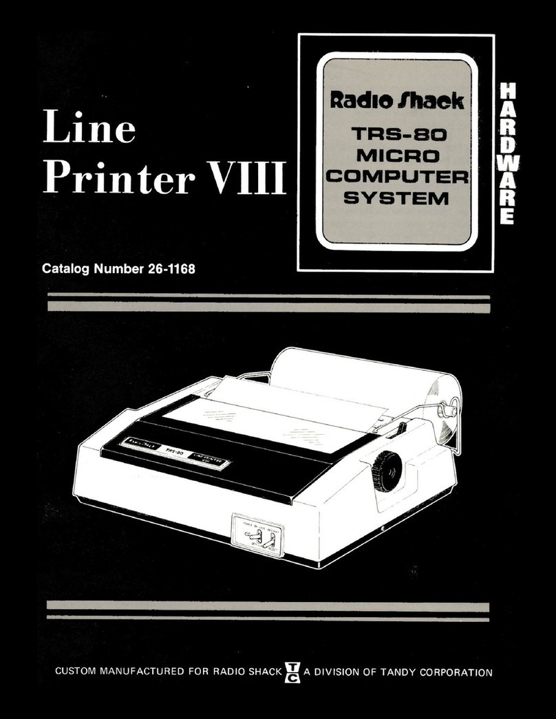
Radio Shack TRS-80 User manual

Radio Shack

Radio Shack TRS-80 User manual

Radio Shack TRS-80 User manual

Radio Shack

Radio Shack TRS-80 User manual

Radio Shack TRS-80 DWP-510 User manual

Radio Shack

Radio Shack TRS-80 DWP-510 User manual

Radio Shack TRS-80 User manual

Radio Shack

Radio Shack TRS-80 User manual

Radio Shack TRS-80 DWP-510 User manual

Radio Shack

Radio Shack TRS-80 DWP-510 User manual

Radio Shack TRS-80 DWP-210 User manual

Radio Shack

Radio Shack TRS-80 DWP-210 User manual

Radio Shack TRS-80 User manual

Radio Shack

Radio Shack TRS-80 User manual

Radio Shack 26-1154A User manual

Radio Shack

Radio Shack 26-1154A User manual

Radio Shack Okidata C6100 User manual

Radio Shack

Radio Shack Okidata C6100 User manual

Radio Shack Line Printer VIII User manual

Radio Shack

Radio Shack Line Printer VIII User manual

Radio Shack TRS-80 MICRO User manual

Radio Shack

Radio Shack TRS-80 MICRO User manual

Radio Shack TRS-80 User manual

Radio Shack

Radio Shack TRS-80 User manual

Radio Shack TRS-80 CGP-220 User manual

Radio Shack

Radio Shack TRS-80 CGP-220 User manual

Radio Shack TRS-80 User manual

Radio Shack

Radio Shack TRS-80 User manual

Radio Shack TRS-80 User manual

Radio Shack

Radio Shack TRS-80 User manual

Radio Shack 26-1190A User manual

Radio Shack

Radio Shack 26-1190A User manual

Radio Shack Daisy Wheel 410 User manual

Radio Shack

Radio Shack Daisy Wheel 410 User manual

Popular Printer manuals by other brands

Konica Minolta magicolor 2430 DL install guide

Konica Minolta

Konica Minolta magicolor 2430 DL install guide

Labelmate PM-300-LS user manual

Labelmate

Labelmate PM-300-LS user manual

Ricoh Aficio SP C820DN operating instructions

Ricoh

Ricoh Aficio SP C820DN operating instructions

Sony DPP--SV77 Service manual

Sony

Sony DPP--SV77 Service manual

Intermec PF8D user guide

Intermec

Intermec PF8D user guide

SHAREBOT VIKING user manual

SHAREBOT

SHAREBOT VIKING user manual

Lexmark M5150 Service manual

Lexmark

Lexmark M5150 Service manual

Canon TR4700 Series Online manual

Canon

Canon TR4700 Series Online manual

Epson ColorPage EPL-C8000 Service manual

Epson

Epson ColorPage EPL-C8000 Service manual

Epson l300 user guide

Epson

Epson l300 user guide

Epson Stylus C82WN Start here

Epson

Epson Stylus C82WN Start here

Lexmark C910 5055-01x Service manual

Lexmark

Lexmark C910 5055-01x Service manual

Brother DCP-9040CN manual 

Brother

Brother DCP-9040CN manual 

Epson Stylus Pro GS6000 Unpacking and setup guide

Epson

Epson Stylus Pro GS6000 Unpacking and setup guide

Epson EPL-6200 Network guide

Epson

Epson EPL-6200 Network guide

Canon 1750 Service manual

Canon

Canon 1750 Service manual

Kyocera Mita S-9100DN Operation guide

Kyocera Mita

Kyocera Mita S-9100DN Operation guide

Monarch 9400 Series user manual

Monarch

Monarch 9400 Series user manual

manuals.online logo
manuals.online logoBrands
  • About & Mission
  • Contact us
  • Privacy Policy
  • Terms and Conditions

Copyright 2025 Manuals.Online. All Rights Reserved.