manuals.online logo
Brands
  1. Home
  2. •
  3. Brands
  4. •
  5. Radio Shack
  6. •
  7. Printer
  8. •
  9. Radio Shack TRS-80 User manual

Radio Shack TRS-80 User manual

Other manuals for TRS-80

46

This manual suits for next models

1

Other Radio Shack Printer manuals

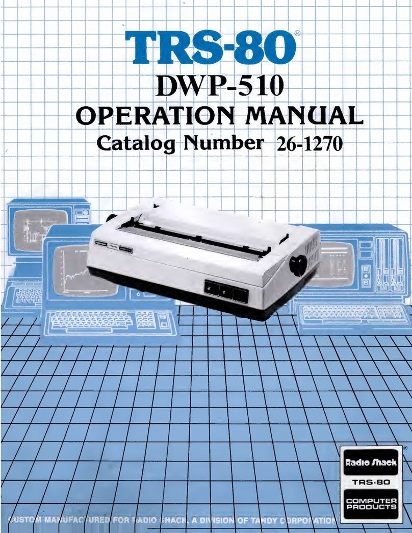
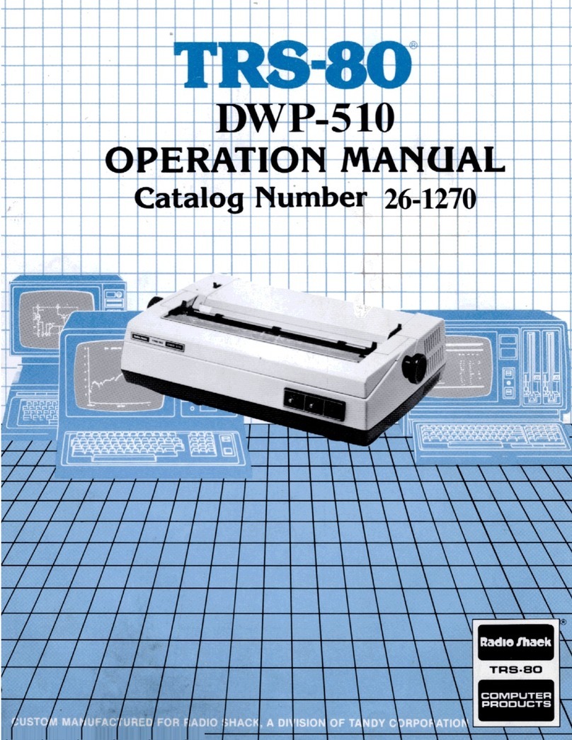
Radio Shack TRS-80 DWP-510 User manual

Radio Shack

Radio Shack TRS-80 DWP-510 User manual

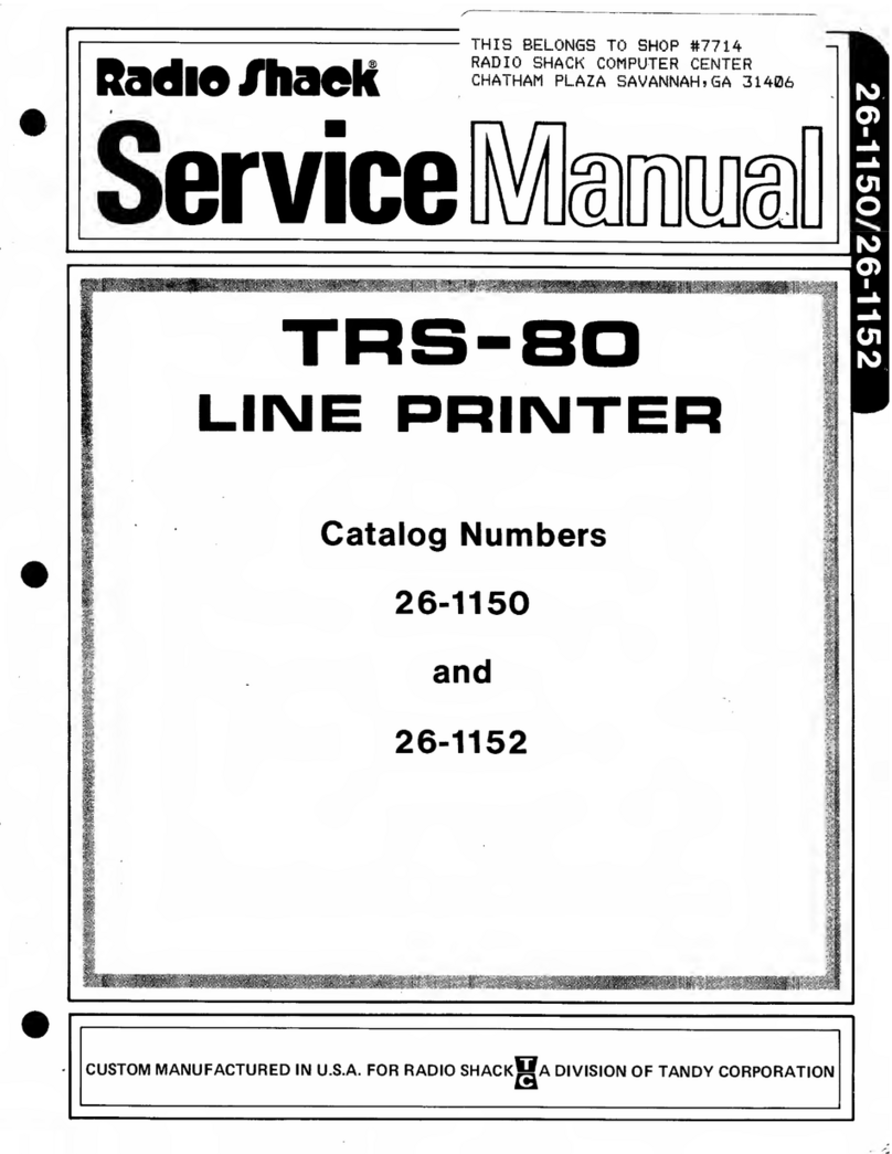
Radio Shack TRS-80 User manual

Radio Shack

Radio Shack TRS-80 User manual

Radio Shack TRS-80 MICRO User manual

Radio Shack

Radio Shack TRS-80 MICRO User manual

Radio Shack TRS-80 User manual

Radio Shack

Radio Shack TRS-80 User manual

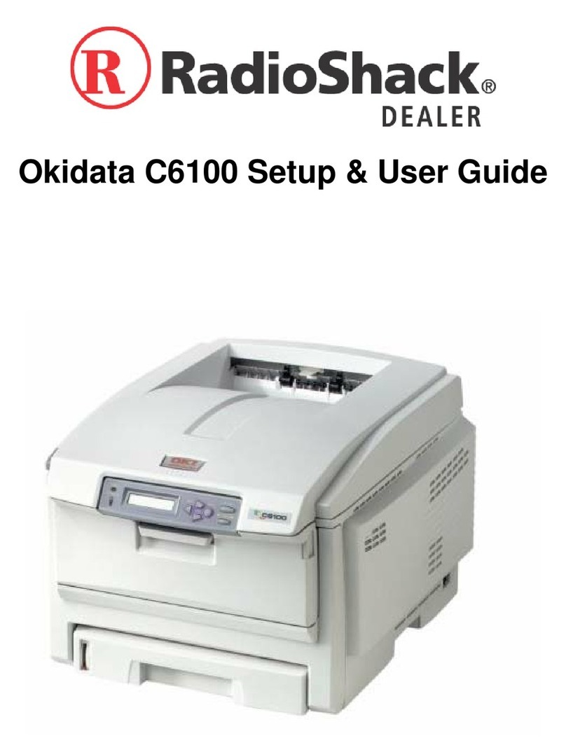
Radio Shack Okidata C6100 User manual

Radio Shack

Radio Shack Okidata C6100 User manual

Radio Shack TRS-80 User manual

Radio Shack

Radio Shack TRS-80 User manual

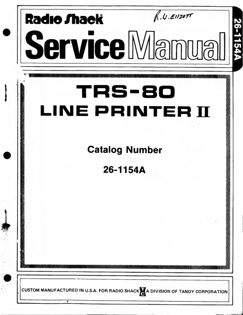
Radio Shack 26-1154A User manual

Radio Shack

Radio Shack 26-1154A User manual

Radio Shack TRS-80 User manual

Radio Shack

Radio Shack TRS-80 User manual

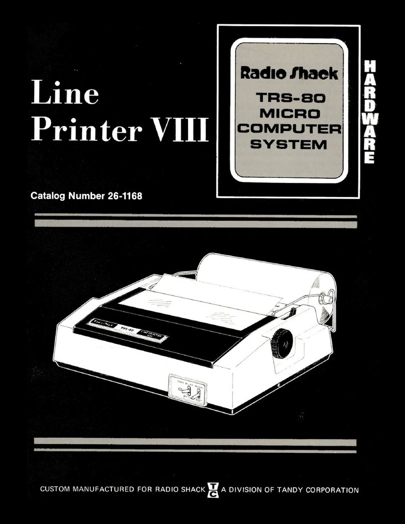
Radio Shack Line Printer VIII User manual

Radio Shack

Radio Shack Line Printer VIII User manual

Radio Shack TRS-80 User manual

Radio Shack

Radio Shack TRS-80 User manual

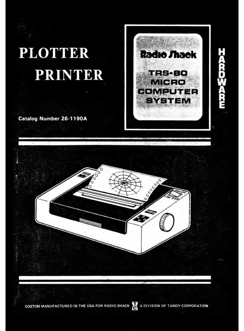
Radio Shack 26-1190A User manual

Radio Shack

Radio Shack 26-1190A User manual

Radio Shack TRS-80 DWP-510 User manual

Radio Shack

Radio Shack TRS-80 DWP-510 User manual

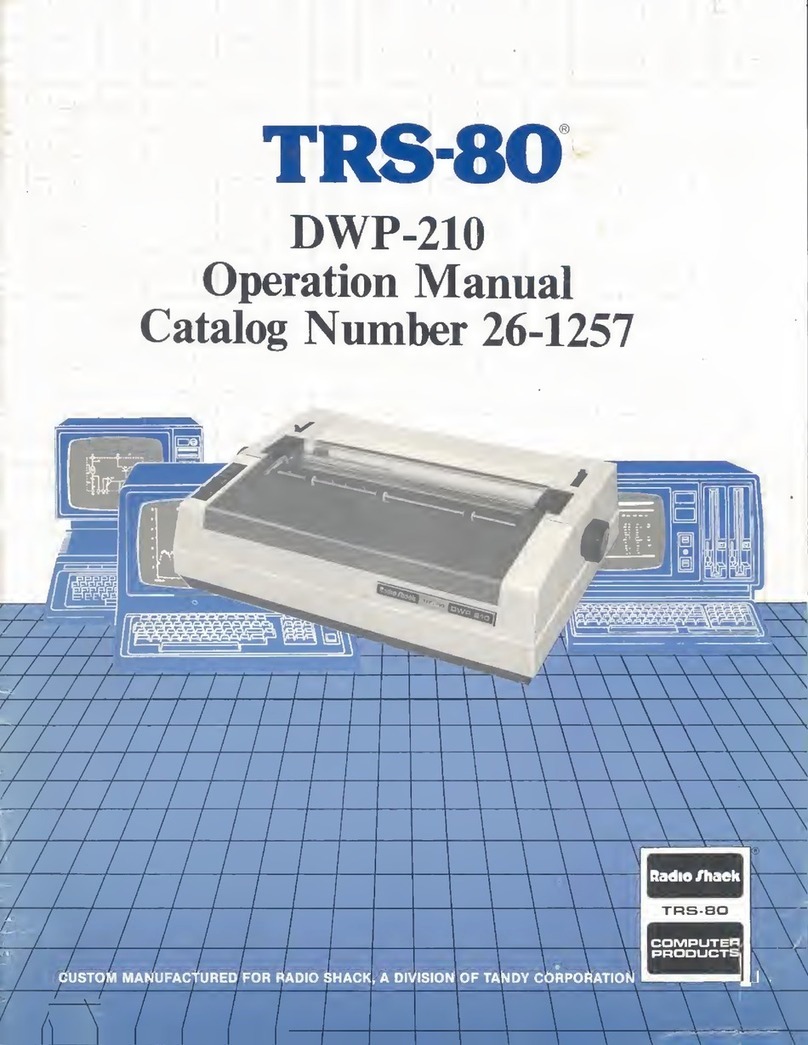
Radio Shack TRS-80 DWP-210 User manual

Radio Shack

Radio Shack TRS-80 DWP-210 User manual

Radio Shack Daisy Wheel 410 User manual

Radio Shack

Radio Shack Daisy Wheel 410 User manual

Radio Shack TRS-80 User manual

Radio Shack

Radio Shack TRS-80 User manual

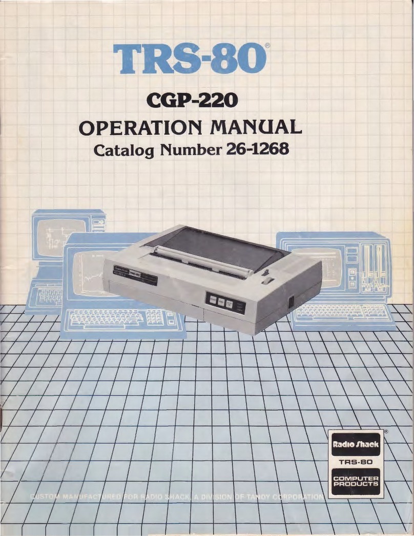
Radio Shack TRS-80 CGP-220 User manual

Radio Shack

Radio Shack TRS-80 CGP-220 User manual

Radio Shack DMP-200 User manual

Radio Shack

Radio Shack DMP-200 User manual

Popular Printer manuals by other brands

Evolis Elypso user guide

Evolis

Evolis Elypso user guide

Lexmark 522n - C Color Laser Printer Service manual

Lexmark

Lexmark 522n - C Color Laser Printer Service manual

Panduit COUGAR LS9Q Operator's manual

Panduit

Panduit COUGAR LS9Q Operator's manual

Olivetti PG L2140 Operation guide

Olivetti

Olivetti PG L2140 Operation guide

Samsung SL-M2820DW user manual

Samsung

Samsung SL-M2820DW user manual

Kyocera FS-9530DN specification

Kyocera

Kyocera FS-9530DN specification

Canon LASER SHOT LBP-1210 Specifications

Canon

Canon LASER SHOT LBP-1210 Specifications

Canon PIXMA PRO-1 Series Getting started

Canon

Canon PIXMA PRO-1 Series Getting started

Canon LBP113w Getting started

Canon

Canon LBP113w Getting started

Lexmark Infoprint 1332 user manual

Lexmark

Lexmark Infoprint 1332 user manual

Epson M1120 user guide

Epson

Epson M1120 user guide

TransAct POSJET 1500 Spare parts

TransAct

TransAct POSJET 1500 Spare parts

Telpar MTP-1500 user manual

Telpar

Telpar MTP-1500 user manual

Star DP8340 SERIES user manual

Star

Star DP8340 SERIES user manual

MGI JETVARNISH 3DS user manual

MGI

MGI JETVARNISH 3DS user manual

Kyocera TASKalfa PA4500ci Operation guide

Kyocera

Kyocera TASKalfa PA4500ci Operation guide

Emaar EP-360 user manual

Emaar

Emaar EP-360 user manual

Fujitsu DL7400 user manual

Fujitsu

Fujitsu DL7400 user manual

manuals.online logo
manuals.online logoBrands
  • About & Mission
  • Contact us
  • Privacy Policy
  • Terms and Conditions

Copyright 2025 Manuals.Online. All Rights Reserved.

(4 ,)rT-1.*;S'-^l Ws«^S?-,
Radio /§saek
/A
MM?k
^^^9 ^B^0 ^^^h Bkm B^mi
IIMT
1
m
Catalog Number 26-1151
CUSTOM MANUFACTURED IN U.S.A. FOR RADIO SHACK MADIVISION OF TANDY CORPORATION
iSPW8WW'-$¥*i^?gBSW
INTRODUCTION
The TRS-80 Screen Printer consists of arotary printer, built-in power supply and 36" (90 cm) interconnect cable. It also
contains apower-ON/OFF switch, power-ON indicator, afuse and aPRINT command switch. The upper half of the case may
be raised for access to the rotary printer for paper replacement. The front has aremovable panel for access to the print head.
This Screen Printer will connect to any TRS-80 Computer and print out whatever information is displayed on the Video
Display screen.
SPECIFICATIONS:
Power Input 120 VAC, 60 Hz
Power Consumption at 120 VAC 60 Watts (Printing)
10 Watts (Standby)
Printing Rate ... *2,200 characters-per-second
Drive-unit Lifetime 500,000 screen printouts
Print-head Lifetime 5,000 screen printouts
CONNECTIONS
NOTE: The word "UP" is printed on the cable connectors To replace the roll of paper, perform the following steps:
to provide correct orientation.
1.Raise the upper half of the case.
Install the interconnect cable between the Screen Printer
and the Computer expansion jack (under the removable 2. Release the snap-down paper-gu,de cover (A) by
.pulling outward on cover latch,
cover). r
Connect the AC power cord to any standard 120 VAC out- 3. Insert the spindle in slots (B). Paper should roll off
.the spool at the bottom toward the rear.
OPERATION 4'Route the PaPer over the to Pspindle (C), with the
coated side down.
NOTE: To avoid malfunctions in computer programs, set 5, Fold the paper to form apointed edge (D).
the power ON/OFF switch to "ON" whenever the
Printer is connected to the Computer. 6. Insert the pointed edge through the writing platen
and pull the paper through until the entire folded
Apply power to the Printer, Computer and Video Display section has passed the cutting edge on the platen (E).
(in any order). Load aprogram into the Computer via tape
cassette or keyboard and display whatever you want to be 7. Align edge of paper with paper guide (F).
printed out. Press the PRINT command switch on the front
of the Printer. The Printer immediately prints out all of the 8. Close the snap-down paper-guide (G).
data that is displayed on the Video screen.
9. Hold the end of the paper and, with an upward motion,
PAPER LOADING (See Figure 1) press the paper firmly against the cutting edge. Con-
tinue the motion to tear the paper off.
Astripe on the paper indicates the end of the roll is
approaching and that the roll should be replaced. You can 10. Close the top half of the case.
buy new rolls of paper through your local Radio Shack store.
(A) RELEASE LATCH
AND LIFT
(Dl FOLD UNDER TO MAKE
APOINTED EDGE
(CI ROUTE PAPER ABOVE
TOP SPINDLE
IBI INSTALL SPOOL
OF PAPER
(G) CLOSE AND SNAP
INTO PLACE
(El INSERT PAPER UNDER
WRITING PLATEN AND
PULL THROUGH
(F) ALIGN EDGE OF PAPER
WITH PAPER GUIDE
FIGURE 1. PAPER LOADING
HEAD ADJUSTMENT PROCEDURE
All printers are given an operational test before leaving the
factory. Only minor adjustments should be required and it
will not be necessary to remove, the print head from its
housing to make any preliminary centering adjustments.
Before proceeding with this procedure, see Figure 2, showing
the end view of the print head with the adjusting screws.
m
FIGURE 2. PRINT HEAD (END VIEW)
Apply power to the printer. Allow it to print out the
video display with at least one full line of repeating ABC
pattern, and remove power. Now look at the vertical
alignment of characters in each line. Observing the first
three characters in aline, determine if one of the three
is out of alignment with the other two. Should the first
character be either higher or lower than the second or third,
refer to the adjustment screw at stylus "A" that is marked
"DN-^-*-UP". Turn this screw counterclockwise 1/4 turn
to remove tension on the head. Now, by bringing the blade
of the screwdriver to bear on the side of the screw head, it
will be possible to move the stylus assembly in the desired
direction. Then tighten the screw to hold the stylus assembly
in place.
Apply power and recheck character alignment. If further
adjustment is required, repeat the procedure. Should the
second character be out of alignment with the first and
third, go through similar adjustment procedures at stylus B.
Likewise, to bring the third character in alignment with the
first and second, make an adjustment at stylus C. Refer to
Figure 3for typical situations and alignment procedures.
When the required vertical adjustments have been made,
pay attention to the spacing between columns Aand B, B
and Cand Cand A. The spaces between columns should be
nearly equal. If not, equalize the spacing by making adjust-
ments with R" "*"L screws associated with each stylus. See
Figure 4for adjustments to make in typical situations.
3
CO
33
>
+»
CO
3
>
*•*
to
ABCA
AA
BC—
ABC
C
A
ABA
Normal alignment
Irregular alignment (Move
stylus "A" down)
Irregular alignment (Move
stylus "B"up)
Irregular alignment (Move
stylus "C" down)
FIGURE 3. VERTICAL CHARACTER ALIGNMENT
00 o
3333
>£&>-
4-»
CO CO CO CO
AA
AB(-» ANormal spacing
AB(~» A
AB (._» AUnequal spacing
AB ^j A(Move stylus B
AB ^> Ato the right)
ABC AUnequal spacing
ABC A(Move stylus C
ABC Ato the right)
AB"» AUnequal spacing
ABr-\ A(Move stylus A
AB C Ato the left)
FIGURE 4. COLUMN CHARACTER ALIGNMENT
CLEANING PROCEDURE
After printing 10 or more rolls of paper asmall amount of
dust will accumulate under the print head assembly. At this
time, the front plate of the housing should be removed and
the dust cleaned out with asmall brush or alcohol saturated
pads.
m
LIMITED WARRANTY
Radio Shack warrants for aperiod of 90 days from the date of delivery
to customer thatjhe computer hardware described herein shall be free
from defects in material and workmanship under normal use and service.
This warranty shall be void if the computer case or cabinet is opened or
if the unit is altered or modified. During this period, if adefect should
occur, the product must be returned to aRadio Shack store or dealer
for repair. Customer's sole and exclusive remedy in the event of defect
is expressly limited to the correction of the defect by adjustment, re-
pair or replacement at Radio Shack's election and sole expense, except
there shall be no obligation to replace or repair items which by their
nature are expendable. No representation or other affirmation of fact,
including but not limited to statements regarding capacity, suitability
for use, or performance of the equipment, shall be or be deemed to be a
warranty or representation by Radio Shack, for any purpose, nor give
rise to any liability or obligation of Radio Shack whatsoever.
EXCEPT AS SPECIFICALLY PROVIDED IN THIS AGREEMENT
THERE ARE NO OTHER WARRANTIES, EXPRESS OR IMPLIED'
INCLUDING, BUT NOT LIMITED TO, ANY IMPLIED WARRANTIES
OF MERCHANTABILITY OR FITNESS FOR APARTICULAR PUR-
POSE AND IN NO EVENT SHALL RADIO SHACK BE LIABLE FOR
LOSS OF PROFITS OR BENEFITS, INDIRECT, SPECIAL CONSE-
QUENTIAL OR OTHER SIMILAR DAMAGES ARISING OUT OF
ANY BREACH OF THIS WARRANTY OR OTHERWISE
m
RADIO SHACK gADIVISION OF TANDY CORPORATION
U.S.A.: FORT WORTH, TEXAS 76102
CANADA: BARRIE, ONTARIO L4M 4W5
AUSTRALIA
TANDY CORPORATION
BELGIUM
280 316 VICTORIA ROAD
RYDALMERE NSW 2116
Ul<
PARC INDUSTRIEL DE NANINNE
5140 NANINNE BILSTON ROAD WEDNESBURY
WEST MIDLANDS WS10 7JN
278-298-0077 PRINTED IN U.S.A.