K-RAIN MANUFACTURING CORP.
1640 Australian Avenue
Riviera Beach, FL 33404 USA
PH: 1-561-844-1002 / 1-800-735-7246
FAX: 1-561-842-9493
www.krain.com
© K-RAIN Manufacturing Corp. 14005103REV13
INSTRUCCIONES DE AJUSTE DEL
ASPERSOR DE TURBINA PROSPORT ™
OBSERVACIÓN: El ProSport viene configurado previamente de fábrica con un ajuste
del sector a 180º e incluye la preinstalación de una tobera del No.10.
CAMBIO DE LA TOBERA
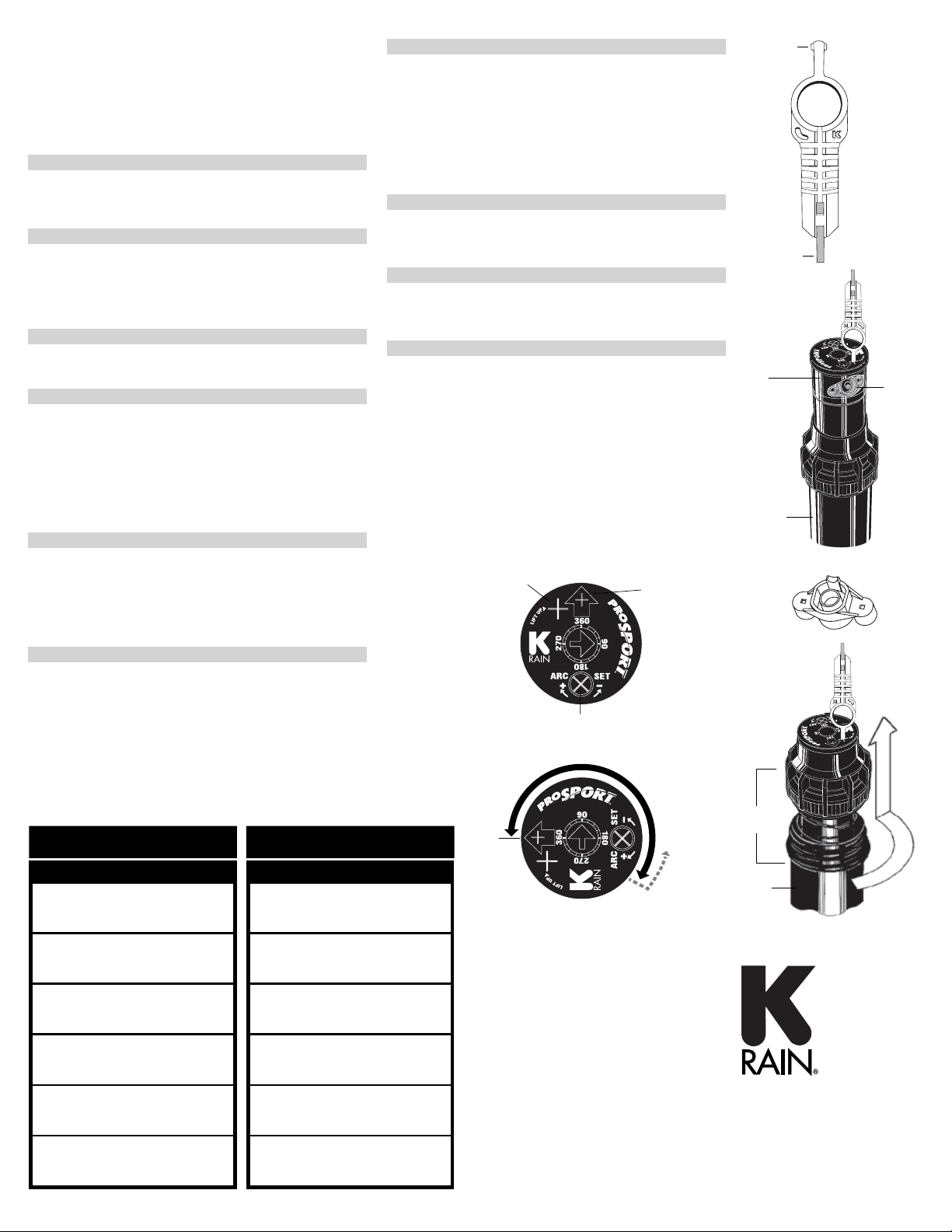
1. CÓMO QUITAR EL TORNILLO DE SUJECIÓN
Utilice la (B) llave o un destornillador pequeño de punta plana para quitar el tornillo
de sujeción de la tobera y gírelo en el sentido contrario al de las agujas del reloj
para quitarlo y en el sentido de las agujas del reloj para volverlo a colocar.
2. ELEVACIÓN DEL VÁSTAGO
Inserte la (A) llave en el orificio situado en la parte superior (J) de la cabeza
giratoria (K) gire la llave ¼ de vuelta para asegurarse de que la llave no se sale del
orificio cuando la levante. Tire hacia arriba y con fuerza del vástago para vencer la
resistencia del muelle, y así acceder al hueco de la tobera (E). Sujete el vástago con
una mano cuando esté arriba.
3. CÓMO QUITAR LA TOBERA
Con unos alicates de puntas, agarre la tobera por el lado del anillo exterior y tire
de la tobera.
4. INSTALACIÓN DE UNA TOBERA
Inserte a presión la tobera deseada en su correspondiente hueco. Asegúrese de
que es visible el número de la tobera y que los “dientes” de ésta están hacia arriba.
A continuación, vuelva a colocar el tornillo de sujeción de la tobera.
OBSERVACIÓN: El tornillo de sujeción de la tobera también permite usarlo de
difusor y acortar la distancia de alcance del chorro.
DETERMINACIÓN DEL AJUSTE
DEL SECTOR
1. CÓMO ENCONTRAR LA POSICIÓN DE ARRANQUE A LA IZQUIERDA
Ponga los dedos en la parte superior central de la cabeza giratoria. Gire la cabeza
hacia la derecha hasta que se pare y a continuación de nuevo hacia la izquierda
hasta que se pare. Observe la posición de la flecha de la tobera. Esta es la posición
de “Arranque a la izquierda”. El aspersor empezará a pulverizar desde esta posición
y a girar en el sentido de las agujas del reloj hasta que llegue a Punto ajustable
derecho de Parada-Retorno.
2. CÓMO ORIENTAR LA POSICIÓN DE ARRANQUE A LA IZQUIERDA
Inserte la (A) llave en el orificio (J) en la parte superior de la cabeza giratoria (K) y
gire la llave ¼ de vuelta para asegurarse de que la llave no se sale del ojo cuando
la levante. Con cuidado de no dejar que gire la cabeza de la tobera, tire con firmeza
del vástago accionado por resorte. Sujete el ensamblaje inferior del vástago con una
mano. A continuación gire únicamente el vástago inferior en el sentido de las agujas
del reloj o contrario a estas hasta que la flecha de la tobera apunte al lugar donde
usted desea empezar a regar.
3. CAMBIO DEL SECTOR
Inserte la
(B) llave en la ranura de ajuste del sector
(M)
. TGírela en el sentido de las
agujas del reloj para aumentar el sector o en sentido contrario a las agujas del reloj
para reducir el sector. OBSERVACIÓN: La flecha de ajuste del sector situada en el
centro de la cabeza de la tobera gira para indicar el ajuste actual.
CUANDO ESTÉ AJUSTADA A 360º, EL PROSPORT GIRARÁ CONTINUAMENTE EN
LA DIRECCIÓN DE LAS AGUJAS DEL RELOJ.
INSTALACIÓN DE LOS ASPERSORES
1. COLOCACION DE LOS ASPERSORES EN EL TERRENO
No utilice TEFLÓN en la rosca. Enrosque el aspersor a la tubería. Entierre el aspersor
al nivel de la superficie. OBSERVACIÓN: Los aspersores de turbina y los difusores
emergentes no deberán ser instalados en el mismo sector de riego.
2. INSPECCIÓN DEL FILTRO
Desenrosque la tapa del aspersor y saque todo el ensamblaje del aspersor (I) de su
carcasa. El filtro está situado en la parte inferior del ensamblaje del aspersor y se
puede sacar, limpiar y volver a instalar fácilmente.
3. CONSEJOS DE CARA AL INVIERNO
Es aconsejable utilizar un compresor de aire para eliminar el agua del sistema de
tuberías y aspersores, a fin de evitar los daños por heladas. Si lo hace tenga en
cuenta lo siguiente:
a. No exceda la presión de 30 PSI (1 Atm (1 Kg/cm2)).
b. Introduzca siempre aire en el sistema de forma gradual para evitar aumentos
repentinos de la presión. Una salida repentina de aire comprimido al aspersor
puede causar daños.
c. Cada una de las zonas deberá funcionar con aire comprimido no más de 1
minuto. Los aspersores giran entre 10 y 12 veces más rápido con aire que con
agua. Un giro excesivo de los aspersores de turbina con aire puede causar daños
a los componentes internos.
FUNCIONAMIENTO
PRESIÓN RADIO CAUDAL
TOBERA PSI FT. GPM
#5 40 45' 5.1
BLANCO 50 47' 5.9
60 47' 6.5
70 49' 7.1
#10 50 53' 10.6
VERDE 60 53' 11.8
INSTALADO 70 53' 12.6
PREVIAMENTE 80 55' 13.5
#15 50 57' 13.0
GRIS 60 59' 14.2
70 59' 15.4
80 63' 16.5
#20 60 65' 18.9
MARRON 70 67' 20.5
80 69' 21.9
90 71' 23.2
#25 60 67' 22.8
AZUL 70 71' 24.8
80 75' 26.5
90 77' 26.8
#30 60 67' 23.7
NEGRO 70 69' 25.6
80 69' 27.5
90 71' 29.2
METRIC
PRESIÓN RADIO CAUDAL
TOBERA KPA BARES METROS L/M M3/H
#5 276 2.76 13.7 19.3 1.16
BLANCO 345 3.45 14.3 22.3 1.34
414 4.14 14.3 24.6 1.48
483 4.83 14.9 26.9 1.61
#10 345 3.45 16.2 40.1 2.41
VERDE 414 4.14 15.9 44.3 2.66
INSTALADO 483 4.83 16.2 47.7 2.86
PREVIAMENTE 552 5.52 16.8 51.1 3.06
#15 345 3.45 17.4 49.2 2.95
GRIS 414 4.14 18.0 53.8 3.23
483 4.83 18.0 58.3 3.50
552 5.52 19.2 62.5 3.75
#20 414 4.14 19.8 71.5 4.29
MARRON 483 4.83 20.4 77.6 4.66
552 5.52 21.0 82.9 4.97
621 6.21 21.6 87.8 5.27
#25 414 4.14 20.4 86.3 5.18
AZUL 483 4.83 21.6 93.9 5.63
552 5.52 22.9 100.3 6.02
621 6.21 23.5 101.4 6.08
#30 414 4.14 20.4 89.7 5.38
NEGRO 483 4.83 21.0 96.9 5.81
552 5.52 21.0 104.1 6.25
621 6.21 21.6 110.5 6.63
RENDIMIENTO DE LAS TOBERAS ESTÁNDAR
M Ajuste del Sector
J Orificio
KCabeza de Tobera
LTornillo de
Sujeción
GTobera
IAspersor
HLlave en Orificio
F
Carcasa
EHueco
de Tobera
CLlave en Orificio
F
Carcasa
K
Cabeza
de Tobera
Llave
A
B
Los datos representan resultados en pruebas efectuadas en el ProSport sin viento.
Arranque a
la izquierda


