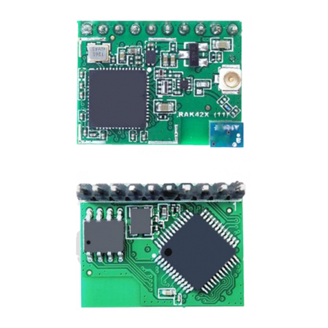
RAK 3172 WisDuo LPWAN User manual

Documentation Center
RAK3172 Module Quick Start Guide
This guide covers the following topics:
RAK3172 as a Stand-Alone Device Using RUI3
RAK3172 as a LoRa/LoRaWAN Modem via AT Command
Connecting to The Things Network (TTN)
Connecting with Chirpstack
LoRa P2P Mode
Prerequisites
What Do You Need?
Before going through the steps in the installation guide of the RAK3172 WisDuo LPWAN Module, make sure to
prepare the necessary items listed below:
Hardware
RAK3172 WisDuo LPWAN Module
Computer
USB to UART TTL adapter
Software
Download and install the Arduino IDE .
⚠
WARNING
If you are using Windows 10.
Do NOT install the Arduino IDE from the Microsoft App Store. Instead, install the original Arduino IDE from
the Arduino official website. The Arduino app from the Microsoft App Store has problems using third-party
Board Support Packages.
Add RAK3172 as a supported board in Arduino IDE by updating Board Manager URLs in Preferences settings
of Arduino IDE with the JSON URL below.
After that, you can then add RAKwireless RUI STM32 Boards via Arduino board manager.
RAK Serial Port Tool
List of Acronyms
https://raw.githubusercontent.com/RAKWireless/RAKwireless-Arduino-BSP-Index/main/package_rakwirel
json

Documentation Center
Product Configuration
RAK3172 as a Stand-Alone Device Using RUI3
Hardware Setup
The RAK3172 requires a few hardware connections before you can make it work. The bare minimum requirement
is to have the power section properly configured, reset button, antenna, and USB connection.
Acronym Definition
DFU Device Firmware Upgrade
JTAG Joint Test Action Group
LoRa Long Range
OTAA Over-The-Air-Activation (OTAA)
ABP Activation-By-Personalization (ABP)
TTN The Things Network
DEVEUI Device EUI (Extended Unique Identification)
APPEUI Application EUI (Extended Unique Identification)
APPKEY Application Key
DEVADDR Device Address
NWKSKEY Network Session Key
APPSKEY Application Session Key
P2P Point-to-Point
MSB Most Significant Bit
LNS LoRaWAN Network Service

Documentation Center
⚠
WARNING
Firmware update is done via UART2 pins. If you will connect the module to an external device that will be
interfacing with UART2, take extra precautions in your board design to ensure you can still perform FW
update to it. There should be a way in your board design that can disconnect the external device to
RAK3172 UART2 before connecting the module to the PC (via USB-UART converter) for the FW update
process.
An alternative option to update firmware aside from UART2 is to use SWD pins (SWCLK & SWDIO). This
method will require you to use external tools like ST-LINK and RAKDAP1.
Figure 1: RAK3172 Minimum Schematic
Ensure that the antenna is properly connected to have a good LoRa signal. Also, note that you can damage the
RF section of the chip if you power the module without an antenna connected to the IPEX connector.
Figure 2: LoRa Antenna
RAK3172 has a module variant with an IPEX connector where you can connect the LoRa antenna, as shown in
Figure 3. If the RAK3172 module you ordered is the variant with no IPEX connector, you need to ensure that there
is an external antenna connected to RF pin (PIN 12) of the module.

Documentation Center
Figure 3: IPEX Connector of RAK3172 for LoRa Antenna
📝
NOTE
Detailed information about the RAK3172 LoRa antenna can be found on the antenna datasheet .
⚠
WARNING
When using the LoRa transceiver, make sure that an antenna is always connected. Using this transceiver
without an antenna can damage the module.
Software Setup
The default firmware of RAK3172 is based on RUI3, which allows you to develop your custom firmware to connect
sensors and other peripherals to it. To develop your custom firmware using Arduino IDE, you need first to add
RAKwireless RUI STM32 Boards in the Arduino board manager, which will be discussed in this guide. You can
then use RUI3 APIs for your intended application. You can upload the custom firmware via UART. The AT
commands of RAK3172 is still available even if you compile custom firmware via RUI3. You can send AT
commands via UART2 connection.
RAK3172 RUI3 Board Support Package in Arduino IDE
If you don't have an Arduino IDE yet, you can download it on the Arduino official website and follow the
installation procedure in the miscellaneous section of this document.
📝
NOTE
For Windows 10 and up users:
If your Arduino IDE is installed from the Microsoft App Store, you need to reinstall your Arduino IDE by
getting it from the Arduino official website. The Arduino app from the Microsoft App Store has problems
using third-party Board Support Packages.
Once the Arduino IDE has been installed successfully, you can now configure the IDE to add the RAK3172 in its
board selection by following these steps.
1. Open Arduino IDE and go to File > Preferences.

Documentation Center
Figure 4: Arduino preferences
2. To add the RAK3172 to your Arduino Boards list, edit the Additional Board Manager URLs. Click the icon, as
shown in Figure 5.
Figure 5: Modifying Additional Board Manager URLs
3. Copy the URL below and paste it on the field, as shown in Figure 6. If there are other URLs already there, just
add them on the next line. After adding the URL, click OK.
https://raw.githubusercontent.com/RAKWireless/RAKwireless-Arduino-BSP-Index/main/package_rakwirel
json

Documentation Center
Figure 6: Add additional board manager URLs
4. Restart the Arduino IDE.
5. Open the Boards Manager from Tools Menu.
Figure 7: Opening Arduino boards manager
6. Write RAK in the search bar, as shown in Figure 8. This will show the available RAKwireless module boards
that you can add to your Arduino Board list.
7. Click on the area highlighted in blue to select RAKwireless RUI STM32 Boards. Install the latest version of the
RAKwireless RUI STM32 Boards by clicking on Install button.

Documentation Center
Figure 8: Installing RAKwireless RUI STM32 Boards
Configure RAK3172 on Boards Manager
8. Once the BSP is installed, select Tools > Boards Manager > RAKWireless RUI STM32 Modules > WisDuo
RAK3172 Evaluation Board. The RAK3172 Evaluation board uses RAK3172 WisDuo module.
Figure 9: Selecting RAK3172 Module
RAK3172 COM Port on Device Manager
Connect the RAK3172 via UART and check RAK3172 COM Port using Windows Device Manager. Double-click
the reset button if the module is not detected.

Documentation Center
Figure 10: Device manager ports (COM & LPT)
Compile an Example with Arduino LED Breathing
1. After completing the steps on adding your RAK3172 to the Arduino IDE, you can now try to run a simple
program to test your setup. You need to add two LEDs to the bare minimum schematic of the RAK3172 module,
as shown in Figure 11.
Figure 11: RAK3172 with two LEDs
2. Launch Arduino IDE and configure WisDuo RAK3172 Evaluation Board on board selection. See Figure 9.
3. Connect the RAK3172 via UART and check RAK3172 COM Port. See Figure 10.
4. Open Tools Menu and select a COM port. COM28 is currently used.

Documentation Center
Figure 12: Select COM port
5. You can see the serial monitor icon and click it to connect COM port.
Figure 13: Open Arduino serial monitor
6. If the connection is successful, you can send AT Commands to RAK3172. For example: To check the RUI
version, type AT+VER=? on the text area, then click on the Send button, as shown in Figure 14.

Documentation Center
Figure 14: Send AT command
Figure 15: Arduino serial monitor COM28
7. Open Arduino_Led_Breathing example code.

Documentation Center
Figure 16: Arduino Led Breathing example
8. Click on the Verify icon to check if you have successfully compiled the example code.
Figure 17: Verify the example code
9. Click the Upload icon to send the compiled firmware to your RAK3172 module.
📝
NOTE:
RAK3172 should automatically go to BOOT mode when the firmware is uploaded via Arduino IDE.
If BOOT mode is not initiated, pull to ground the RESET pin twice (or double click the reset button if
available) to force BOOT mode.

Documentation Center
Figure 18: Upload the example code
10. If the upload is successful, you will see the Upgrade Complete message.
Figure 19: Device programmed successfully
11. After the Device Programmed is completed, you will see that LEDs are blinking.
RAK3172 I/O Pins and Peripherals
This section discusses how to use and access RAK3172 pins using RUI3 API. It shows basic code on using digital
I/O, analog input, UART, and I2C.

Documentation Center
Figure 20: Available Peripherals and Digital I/O pins in RAK3172 module
How to Use Digital I/O
You can use any of the pins below as Digital Pin.

Documentation Center
Pin Name Alternative Pin Usage
PA0
PA1
PA4 SPI
PA5 SPI
PA6 SPI
PA7 SPI
PA8
PA9 I2C_SCL
PA15
PB2
PB3 ADC1
PB4 ADC2
PB5
PB6 UART1_TX
PB7 UART1_RX
PB12

Documentation Center
Figure 21: Available Digital I/O pins in RAK3172 module
The pins listed below must not be used.
Use Arduino digitalRead to read the value from a specified Digital I/O pin, either HIGH or LOW.
Use Arduino digitalWrite to write a HIGH or a LOW value to a Digital I/O pin.
📝
NOTE:
The GPIO Pin Name is the one to be used on the digitalRead and digitalWrite and NOT the pin numbers.
Example code
Pin name Pin Usage
PA2 UART2_TX
PA3 UART2_RX
PA13 SWDIO
PA14 SWCLK
PB8 RAK3172 Internal

Documentation Center
How to Use Analog Input
You can use any of the pins below as Analog Input.
Use Arduino analogRead to read the value from the specified Analog Input pin.
Figure 22: Available Analog pins in RAK3172
Example code
Analog Port Pin Name
ADC1 PB3
ADC2 PB4
void setup()
{
pinMode(PA0, OUTPUT); //Change the P0_04 to any digital pin you want. Also, you can set this to
}
void loop()
{
digitalWrite(PA0,HIGH); //Change the PA0 to any digital pin you want. Also, you can set this to
delay(1000); // delay for 1 second
digitalWrite(PA0,LOW); //Change the PA0 to any digital pin you want. Also, you can set this to
delay(1000); // delay for 1 second
}
c

Documentation Center
How to Use Serial Interfaces
UART
There are two UART peripherals available on the RAK3172 module. There are also different Serial Operating
Modes possible in RUI3, namely Binary Mode , AT Mode , and Custom Mode .
Figure 23: Available UART pins in RAK3172
Example Code
Serial Port Serial Instance Assignment Default Mode
UART1 (pins 4, 5) Serial1 Custom Mode
UART2 (pins 1, 2) Serial AT Command
#define analogPin PB3
int val = 0; // variable to store the value read
void setup()
{
Serial.begin(115200);
}
void loop()
{
val = analogRead(analogPin); // read the input pin
Serial.println(val); // debug value
delay(100);
}
c

Documentation Center
I2C
There is one I2C peripheral available on RAK3172.
Use Arduino Wire library to communicate with I2C devices.
Figure 24: Available I2C pins in RAK3172
Example Code
Make sure you have an I2C device connected to specified I2C pins to run the I2C scanner code below:
I2C Pin Number I2C Pin Name
PA9 I2C_SCL
PA10 I2C_SDA
void setup()
{
Serial1.begin(115200); // use Serial1 for UART1 and Serial for UART2
// you can designate separate baudrate for each.
Serial.begin(115200);
}
void loop()
{
Serial1.println("RAK3172 UART1 TEST!");
Serial.println("RAK3172 UART2 TEST!");
delay(1000); // delay for 1 second
}
c

Documentation Center
The Arduino Serial Monitor shows the I2C device found.
#include <Wire.h>
void setup()
{
Wire.begin();
Serial.begin(115200);
while (!Serial);
Serial.println("\nI2C Scanner");
}
void loop()
{
byte error, address;
int nDevices;
Serial.println("Scanning...");
nDevices = 0;
for(address = 1; address < 127; address++ )
{
// The i2c_scanner uses the return value of
// the Write.endTransmission to see if
// a device did acknowledge to the address.
Wire.beginTransmission(address);
error = Wire.endTransmission();
if (error == 0)
{
Serial.print("I2C device found at address 0x");
if (address<16)
Serial.print("0");
Serial.print(address,HEX);
Serial.println(" !");
nDevices++;
}
else if (error==4)
{
Serial.print("Unknown error at address 0x");
if (address<16)
Serial.print("0");
Serial.println(address,HEX);
}
}
if (nDevices == 0)
Serial.println("No I2C devices found\n");
else
Serial.println("done\n");
delay(5000); // wait 5 seconds for next scan
}
c

Documentation Center
SPI
If your RUI3 project uses SPI, then PA4 to PA7 pins are reserved for RUI3 SPI interface.
📝
NOTE:
PA13 and PA14 pins are reserved for SWD debug interface. Check the Connect to the RAK3172 section.
LoRaWAN Example
This example illustrates how to program RAK3172 module as a stand-alone LoRaWAN end-device via RUI3
Arduino APIs . To use RAK3172 module as a LoRaWAN end-device, it needs to be within reach of a working
LoRaWAN gateway registered to a LoRaWAN network server(LNS) or with a built-in network server.
📝
NOTE:
If you are new to LoRaWAN, here are a few good references about LoRaWAN and gateways:
LoRaWAN 101
What is a LoRaWAN Gateway
How do LoRaWAN® Gateways work?
Things to Consider When Picking A LoRaWAN® Gateway
RAKwireless LoRaWAN gateway models like WisGate Edge have built-in network servers. It is also
common that the LoRaWAN network server is external or in the cloud. The popular LoRaWAN network
server in the cloud that you can use for free (but offers enterprise service, too) is TTN .
To correctly run this example, it is necessary to configure the LoRaWAN parameters and create an OTAA
application on your LoRaWAN gateway.
Register the LoRaWAN Gateway on TTNv3 Community Edition
After configuring your gateway, you need to register it in TTNv3:
1. Login to TTNv3 Network Server with a web browser.
Europe
North America
Australia
2. Navigate to the Console page and click on gateway icon, as shown in Figure 20.
17:29:15.690 -> Scanning...
17:29:15.738 -> I2C device found at address 0x28 !
17:29:15.831 -> done
17:29:15.831 ->
17:29:20.686 -> Scanning...
17:29:20.733 -> I2C device found at address 0x28 !
17:29:20.814 -> done
17:29:20.814 ->
c
Table of contents
Other RAK Control Unit manuals

RAK
RAK WisDuo Series User manual

RAK
RAK WisCore-LoRa RAK3401 User manual

RAK
RAK WisTrio LoRa Tracker User manual

RAK
RAK RAK566 User manual

RAK
RAK WisLink-Cellular RAK2011 User manual

RAK
RAK WisBlock RAK19011 User manual

RAK
RAK WisBlock RAK19016 User manual

RAK
RAK RAK4260 User manual

RAK
RAK RAK1901 User manual
RAK
RAK WisBlock RAK13005 User manual
Popular Control Unit manuals by other brands

ICP DAS USA
ICP DAS USA GPS-721-MRTU quick start guide

H3C
H3C SecPath NSQ1FAB08D0 quick start guide

Asco
Asco 8215 Series Installation & maintenance instructions

CLA-VAL
CLA-VAL 43-01/643-01 Installation, operation and maintenance manual

Hofmann
Hofmann 97 01 930 manual

CLA-VAL
CLA-VAL 50-49 Installation, operation & maintenance manual