Randell 8000D-290 Series User manual

OPERATOR MANUAL
IMPORTANT INFORMATION, KEEP FOR OPERATOR
Information contained in this document is known to be current and accurate at the time of printing/creation. Unified Brands recommends
referencing our product line websites, unifiedbrands.net, for the most updated product information and specifications. © 2019 Unified Brands.
All Rights Reserved. Unified Brands is a wholly-owned subsidiary of Dover Corporation.
1055 Mendell Davis Drive, Jackson, MS 39272
888-994-7636, fax 888-864-7636
unifiedbrands.net
PART NUMBER PP MNL1903, REV. A (03/19)
This manual provides information for:
8000D-290 SERIES PREP TABLES
THIS MANUAL MUST BE RETAINED FOR FUTURE REFERENCE. READ,
UNDERSTAND AND FOLLOW THE INSTRUCTIONS AND WARNINGS
CONTAINED IN THIS MANUAL.
FOR YOUR SAFETY Do not store or use gasoline or other flammable vapors
and liquids in the vicinity of this or any other appliance.
WARNING R290 flammable refrigerant in use. Improper installation,
adjustment, alteration, service or maintenance can cause property
damage, injury or death. Read the installation, operating and maintenance
instructions thoroughly before installing or servicing this equipment.
NOTIFY CARRIER OF DAMAGE AT ONCE It is the responsibility of the
consignee to inspect the container upon receipt of same and to determine
the possibility of any damage, including concealed damage. Unified
Brands suggests that if you are suspicious of damage to make a notation
on the delivery receipt. It will be the responsibility of the consignee to file
a claim with the carrier. We recommend that you do so at once.
Manufacture Service/Questions 888-994-7636.
RETAIN THIS MANUAL FOR FUTURE REFERENCE
NOTICE: Due to a continuous program of product improvement, Unified Brands
reserves the right to make changes in design and specifications without prior notice.
NOTICE: Please read the entire manual carefully before installation. If certain
recommended procedures are not followed, warranty claims will be denied.
MODELNUMBER_________________________
SERIAL NUMBER _________________________
INSTALLATION DATE ______________________
The serial number is located behind the hinged vented
door of the compressor machine compartment. An
example is shown here.
EQUIPMENT DESCRIPTION
MODEL PAN
CAPACITY
1/3 SIZE
L D H DOORS STORAGE
CU. FT.
HP VOLT AMPS NEMA SHIP
WT.
WORK
SURFACE
FRONT OF
TOP RAIL
OVERALL
(COVER OPEN)
8148D-290 11 48” 33” 35” 18.5” 64” (1)24” 9.0 (1)1/3, (1)1/4 115/60/1 5.8 5-15P 495
8272D-290 19 72” 33” 35” 18.5” 64” (2)27” 17.76 (1)1/3, (1)1/4 115/60/1 5.8 5-15P 808

2 OM-8000D SERIES PREP TABLES
INSTALLATION
CAUTION: THIS UNIT CONTAINS R290 FLAMMABLE REFRIGERANT. USE CAUTION
WHEN HANDLING MOVING AND USE OF THE REFRIGERATOR OR FREEZER.
AVOID DAMAGING THE REFRIGERANT TUBING OR INCREASE THE RISK OF A
LEAK.
WARNING:
FAILURE TO FOLLOW INSTALLATION GUIDELINES AND
RECOMMENDATIONS MAY VOID THE WARRANTY ON YOUR UNIT.
WARNING: IT IS IMPORTANT THAT YOUR UNIT HAS ITS OWN DEDICATED LINE.
CONDENSING UNITS ARE DESIGNED TO OPERATE WITH A VOLTAGE
FLUCTUATION OF PLUS OR MINUS 10% OF THE VOLTAGE INDICATED ON
THE UNIT DATA TAG. BURN OUT OF A CONDENSING UNIT DUE TO EXCEEDING
VOLTAGE LIMITS WILL VOID THE WARRANTY.
THE DANFOSS CONTROLLER HAS LOW VOLTAGE PROTECTION AND WILL
NOT OUTPUT VOLTAGE TO THE COMPRESSOR IF VOLTAGE IS LESS THAN
104V.
WARNING: IT IS IMPORTANT THAT A VOLTAGE READING BE MADE AT THE COMPRESSOR
MOTOR ELECTRICAL CONNECTIONS, WHILE THE UNIT IS IN OPERATION
TO VERIFY THE CORRECT VOLTAGE REQUIRED BY THE COMPRESSOR IS
BEING SUPPLIED. LOW OR HIGH VOLTAGE CAN DETRIMENTALLY AFFECT
OPERATION AND THEREBY VOID ITS WARRANTY.
WARNING:
EVAPORATOR FANS RUN CONTINUOUSLY WHILE THE BASE IS POWERED ON.
WARNING: THIS UNIT IS INTENDED FOR USE IN LABORATORIES IN COMMERCIAL,
INDUSTRIAL, OR INSTITUTIONAL OCCUPANCIES AS DEFINED IN THE
SAFETY STANDARD FOR REFRIGERATION SYSTEMS, ASHRAE 15.
SELECTING A LOCATION FOR YOUR NEW UNIT
The following conditions should be considered when selecting a location for
your unit:
1. Floor Load: The area on which the unit will rest must be level, free of vibration,
and suitably strong enough to support the combined weights of the unit plus
the maximum product load weight. All casters must be in contact with the floor
to support the weight. Casters may require shims in order for the caster to be
in contact with the floor. NOTE: If there is a question pertaining to weight load
limits, consult the factory at 1-888-994-7636.
2. Ventilation: The air cooled self contained unit requires a sufficient amount
of cool clean air. Avoid surrounding your unit around other heat generating
equipment and out of direct sunlight. Also, avoid locating in an unheated
room or where the room temperature may drop below 70° F (21°C) or above
86°F (32°C). Do not place any object that can block the ventilation exhaust
from the machine compartment register.
3. Clearance: This units clearance requirements are 0 in. at the top, 0 in. at the
rear and 0 in. at each side.
INSTALLATION CHECKLIST
After the final location has been determined, refer to the following checklist prior
to start-up:
1. Check all exposed refrigeration lines to ensure that they are not kinked,
dented, or rubbing together or rubbing against any steel.
2. Check all visible components for any potential damage.
3. Check that the condenser and evaporator fans rotate freely without striking
any stationary members.
4. Unit must be property leveled; Check all legs or casters ensure they all are
in contact with the floor while maintaining a level work surface. Adjusting
bullet feet height or shimming casters may be necessary if the floor is not
level. NOTE: Damage to equipment may result if not followed. Unified
Brands is not responsible for damage to equipment if improperly installed.
5. Plug unit into power source. Unit will come on. If unit does not turn on, refer
to controller operation section of this manual to manually turn on the unit.
6. Allow unit time to cool down to holding temperature. If temperature
adjustments are required, the control is located on the front panel. Confirm
that the units is holding the desired temperature.
7. If unit has drawers, check drawer to ensure the drawer slides freely and fully
extents along with seating in the cabinet properly when closed.
8. Refer to the front of this manual for serial number location. Please record
this information in your manual on page 1 now. It will be necessary when
ordering replacement parts or requesting warranty service.
9. Allow your unit to operate for approximately 45 minutes before putting in
food in the rail. Allow 2 hours for base of the unit to cool down to storage
temperature, prior to loading product. NOTE: All motors are oiled and sealed.
ELECTRICAL SUPPLY
The wiring should be done by a qualified electrician in accordance with local
electrical codes. A properly wired and grounded outlet will assure proper
operation. Please consult the data tag attached to the compressor to ascertain
the correct electrical requirements. Supply voltage and amperage requirements
are located on the serial number tag located on the rear interior wall.
IMPORTANT - READ FIRST - IMPORTANT
INTERIOR EVAPORATOR COVER
EXTERIOR OF UNIT
NEAR EXPOSED REFRIGERANT TUBING
NEAR MACHINE COMPARTMENT AND NAMEPLATE

3 OM-8000D SERIES PREP TABLES
OPERATION
EASY MORNING STARTUP
1. Turn on the condiment rail by pressing and holding the rail control power button until the LED
display turns on. Let the unit cool for a minimum of 45 minutes.
2. Load the product pans as needed. The loaded product should be 36ºF or below for best results.
FOOD-SAFE OPERATIONS
1. Closing the lids on the condiment rail during non-peak hours will extend the holding time of
food product.
2. The frost above the product pans may come and go during the day -- this is normal. The unit
automatically regulates the rail temperature to keep your food safe and fresh.
NIGHTLY ENERGY-SAVING SHUTDOWN
1. Remove the product pans from the upper rail and place in the conveniently located base storage,
or any other suitable cold-storage area.
2. Turn off the condiment rail by pressing and holding the rail control power button until the LED
display turns off.
3. Remove any food "spillage" or debris, rinse and sanitize rail removing any excess water through
the drain system located at the end of the unit into a suitable water tight container.
4. Close the rail lid to minimize dust and debris contamination.
5. The base will continue to operate normally and may be used for overnight storage.
This equipment is intended for use in rooms having an ambient temperature of 30ºC/86ºF or less.
(NSF labeling requirement). Contact factory for Spanish instructions at 888.994.7636.
MECHANICAL COMPARTMENT
WARNING: BASE EVAPORATOR FANS ARE ALWAYS IN OPERATION WHEN THE UNIT IS
ENERGIZED. DISCONNECT POWER TO THE UNIT PRIOR TO PERFORMING
MAINTENANCE.
1. To power on the base, press and hold the base control power button until the
LED display turns on. To power on the rail, press and hold the rail control
power button until the LED display turns on. The power controls are located
above the louver panel. Both upper and lower rail are controlled by controller
marked Rail.
2. To power off the base press and hold the base control power button until the
LED display turns off. To power off the rail press and hold the rail control power
button until the LED display turns off. The power controls are located above the
louver panel.
3. The drain valve for the upper
rail is found behind the vented
door. The rail may be drained by
placing a pan under the drain
valve and opening the valve.
(See Evening Shut Down of Prep
Rail).
MORNING STARTUP OF PREP RAIL
1. Unit cleaning may be performed at this time.
2. Turn on unit. See item 2 under the Mechanical Compartment section above for
powering on the rail.
3. Allow a minimum 45 minutes for your unit to cool down before loading product.
A uniform frost pattern will appear on side walls and bottom of prep rail area.
4. Load the product and proceed with food preparation. NOTE: Product entering
unit must be at 35°F +/- 2°F.
EVENING SHUT DOWN OF PREP RAIL
1. Remove product from unit at the end of the day’s preparation.
2. Turn off unit. See item 3 under the Mechanical Compartment section above for
powering on the rail.
3. Unit cleaning may be performed at this time if the frost has melted off the
surface.
4. Once defrosted, the rail drain may be opened to remove any water that has
resulted from the defrosting procedure.
WARNING: IT IS RECOMMENDED TO ONLY MAKE CHANGES OF 2 DEGREE INCREMENTS
AT A TIME. ALLOW FOR THE UNIT TO OPERATE 24 HOURS BETWEEN
ADJUSTMENTS. IF THE 2 DEGREE ADJUSTMENT IS NOT ENOUGH ANOTHER
ADJUSTMENT CAN BE MADE. IF THE SETTINGS NEED TO GO ABOVE OR
BELOW THIS POINT THERE MAY BE OTHER CONTRIBUTING FACTORS AS
TO THE CAUSE OF THE TEMPERATURE VARIANCES, PLEASE CONTACT THE
FACTORY AT 1-800-621-8560.
AMBIENT CONDITIONS
Unit is designed for normal operating temperatures between 70° F (21°C) - 86°F
(32°C). Operating outside of those temperatures may cause premature product
wear or failure.
Unified Brands has attempted to preset the temperature control to ensure that
your unit runs at an optimum temperature, but due to varying ambient conditions,
including elevation, food type and your type of operation, you may need to alter
this temperature using control adjustment until desired temperature is reached.
DANFOSS CONTROLLER OPERATION
LED FUNCTION
Compressor energized & Evaporator fan de-energized
Defrost in progress
Fans delay after defrost completion
Evaporator fan energize
An alarm is occurring
ºC / ºF Temperature unit
POWER ON / OFF
MANUAL DEFROST
CHANGE SET POINT
POWER ON / OFF: Press and hold the power button until LED display turns On / Off
MANUAL DEFROST: Press and hold “Defrost” Button
CHANGE SET POINT: To raise temperature
1. Press and hold “ ” to access set point.
2. When set point start flashing, Press “ ” to adjust set point.
3. After 30 seconds, the display automatically reverts to showing the current
temperature.
CHANGE SET POINT: To lower temperature
1. Press and hold “v” to access set point.
2. When set point start flashing, Press “v” to adjust set point.
3. After 30 seconds, the display automatically reverts to showing the current
temperature.

4 OM-8000D SERIES PREP TABLES
CHANGE FROM ºF /ºC :
1. Press the up/down buttons simultaneously for 5 seconds to access the menu.
2. Password is requested. Password is 000.
3. Press the bottom left button to OK the password.
4. Using the up/down buttons, navigate to the “diS” level. Press the bottom left
button to OK the selection.
5. Using the up/down buttons, navigate to the “CFu” level. Press the bottom left
button to OK the selection.
a. “-F” designates Fahrenheit.
b. “-C” designates Celsius.
6. Press the top left button repeatedly to return to exit and return to the home
screen.
DRAINING THE RAIL
1. Open mechanical compartment door
2. Place container under drain valve
3. Open valve until all water has drained
4. Close valve
5. Discard water
DRAWER REMOVAL
1. Fully extend the drawer that is to be removed.
2. Remove product pans from drawer.
3. Lift up the drawer stop tabs on each side of drawer track.
4. Pull drawer out while lifting the tabs.
DRAWER INSTALLATION
To remove and re-install individual drawers and drawer tracks, please refer to the
figure above for proper installation instructions.
MAINTENANCE
WARNING: DO NOT USE SHARP UTENSILS AND/OR OBJECTS.
WARNING: DO NOT USE STEEL PADS, WIRE BRUSHES, SCRAPERS, OR CHLORIDE
CLEANERS TO CLEAN YOUR STAINLESS STEEL.
CAUTION: DO NOT USE ABRASIVE CLEANING SOLVENTS, AND NEVER USE
HYDROCHLORIC ACID (MURIATIC ACID) ON STAINLESS STEEL.
WARNING: DO NOT PRESSURE WASH EQUIPMENT AS DAMAGE TO ELECTRICAL
COMPONENTS MAY RESULT.
Unified Brands strongly suggests a preventive maintenance program which would
include the following monthly, weekly, and daily procedures:
If a failure of the equipment is a direct result of any of the Preventative Maintenance
guidelines being neglected, the repairs and parts replacements will not be covered
under warranty.
It is recommended that the customer contact the local Authorized Service Agent to
provide a quote to perform periodic Preventative Maintenance.
WEEKLY PM PROCEDURES
1. Clean all gaskets on a weekly if not daily basis with a solution of warm water
and a mild detergent to extend gasket life. Do not use bleach for cleaning
gaskets. Bleach will cause the gaskets to become brittle and not reach their
normal life expectancy.
2. Clean and disinfect rail drains with a solution of warm water and mild
detergent on a weekly basis. It is recommended to open and close the drain
valve as the hot water is flowing through to clean any debris from the internal
valve components.
MONTHLY PM PROCEDURES
1. Cleaning of all condenser coils on a monthly basis. Condenser coils are a
critical component in the life of the compressor and must remain clean to
assure proper air flow and heat transfer. Failure to maintain this heat transfer
will affect unit performance and eventually destroy the compressor. Clean the
condenser coils with coil cleaner and/or a vacuum, cleaner and brush. NOTE:
Brush coil in direction of fins, normally vertically as to not damage or restrict
air from passing through condenser.
2. Clean and disinfect drain lines and evaporator pan with a solution of warm
water and mild detergent on a monthly basis. Remove clear plastic drain line
from plastic tray of condensing unit and place pan under end of drain tube.
Discard waste water from pan when cleaning is complete. Re-insert plastic
drain tube into position on condensing unit.
3. Remove drawer tracks as per instructions on Drawer Installation guidelines.
Once drawers are removed wipe away any debris buildup from the drawer
tracks.
The roller bearings come lubricated from the factory. Excessive oils and or
water may remove the oils. It may be required to add lithium grease from time
to time on bearings that appear dry.
4. Inspect all silicone seams at interior of the rail and refrigerated base cabinet
on a monthly basis. Re-apply food grade silicone sealant as needed to any
seams where silicone has peeled away or cracked. Apply silicone to a clean
dry surface. Allow sufficient drying time to assure best adhesion of sealant.
RECOMMENDED CLEANERS FOR YOUR STAINLESS STEEL INCLUDE THE
FOLLOWING:
JOB CLEANING AGENT COMMENTS
Routine cleaning Soap, ammonia,
detergent Medallion
Apply with a sponge or
cloth
Fingerprints and smears Arcal 20, Lac-O-Nu,
Ecoshine Provides a barrier film
Stubborn stains and
discoloration
Cameo, Talc, Zud,
First Impression
Rub in the direction of
the polish lines

5 OM-8000D SERIES PREP TABLES
SERVICE
CAUTION: COMPONENT PARTS SHALL BE REPLACED WITH FACTORY OEM PARTS.
SERVICE WORK SHALL BE DONE BY FACTORY AUTHORIZED SERVICE
PERSONNEL, SO AS TO MINIMIZE THE RISK OF POSSIBLE IGNITION DUE TO
INCORRECT PARTS OR IMPROPER SERVICE.
CAUTION: BEFORE MAKING ANY REPAIRS, ENSURE THE UNIT IS DISCONNECTED
FROM ITS POWER SOURCE.
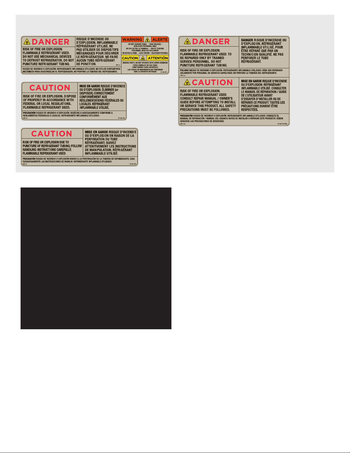
This piece of equipment uses a R290 Refrigeration system. This equipment has
been clearly marked on the serial tag the type of refrigerant that is being used.
There is also a warning labels stating that the unit contains R290 refrigerant. R290
is safe to use as long as you follow these warning labels.
No smoking or open flames when servicing this equipment. If needed, use a CO2
or dry-powder type fire extinguisher
Replacement parts used on any R290 Refrigeration system cabinet must have
specific UL certification for non-sparking components.
Only authorized service technician, certified in R290 system should service this
equipment.
MANIFOLD SET
A R134A manifold set can be used for servicing this equipment.
REFRIGERANT RECOVERY
Follow all national and local regulations for R-290 refrigerant recovery.
LEAKING CHECKING AND REPAIR
Leak check an R-290 system the same way you would an R-134a or R-404A
system with the following exceptions.
1. Do not use a Halid leak detector on a R290 system.
2. Electronic leak detector must be designated specifically for combustible gas.
Use of a bubble solution or an ultrasonic leak detector are acceptable.
When repairing a leak, it is recommended using oxygen free dry nitrogen with a
trace gas not exceeding 200PSI.
When accessing an R290 system, piercing valves are not to remain on the
equipment in a permanent manner. After charge is recovered, Schrader valves
are to be installed on the process stubs. Proper charge is to be weighed into the
system and the system is to be leak checked afterwards.
The R290 equipment must have red process tubes and other devices through
which the refrigerant is serviced, such as any service port. This color marking
must remain on the equipment. If marking is removed, it must be replace and
extend at least 2.5 centimeters (1”) from the compressor.
CHARGING
Follow the charge amount specified on the data tag. It is recommended to use the
shortest hoses possible to prevent undercharging.
• Ensure the system is sealed and leak checked
• Evacuate system to a minimum 500 micron
• Weigh in correct charge
• Leak check the system again
• Bleed the refrigerant from the high side hose to the low side hose
• Disconnect the hoses
• Remove line taps
Greasy and fatty acids, blood,
burnt-on foods
Easy-Off, Degrease It,
Oven Aid
Excellent removal on all
finishes
Grease and Oil Any good commercial
detergent
Apply with a sponge or
cloth
Restoration/Preservation Benefit, Super Sheen Good idea monthly
Reference: Nickel Development Institute, Diversey Lever, Savin, Ecolab, NAFEM
Proper maintenance of equipment is the ultimate necessity in preventing costly
repairs. By evaluating each unit on a regular schedule, you can often catch
and repair minor problems before they completely disable the unit and become
burdensome on your entire operation.
For more information on preventive maintenance, consult your local service
company or CFESA member. Most repair companies offer this service at very
reasonable rates to allow you the time you need to run your business along with
the peace of mind that all your equipment will last throughout its expected life.
These services often offer guarantees as well as the flexibility in scheduling or
maintenance for your convenience. For a complete listing of current Unified Brands
ASA please visit www.unifiedbrands.net.
Unified Brands believes strongly in the products it manufactures and backs those
products with one of the best warranties in the industry. We believe with the
proper maintenance and use, you will realize a profitable return on your investment
and years of satisfied service.
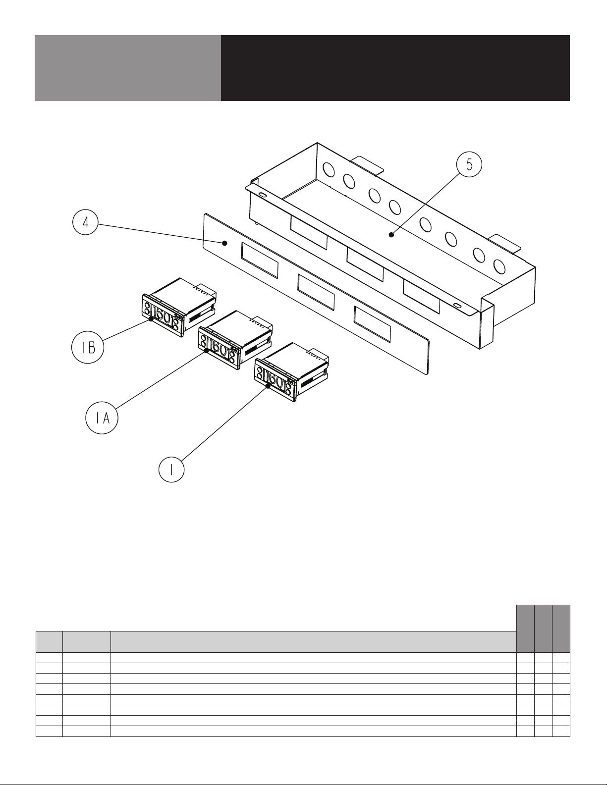
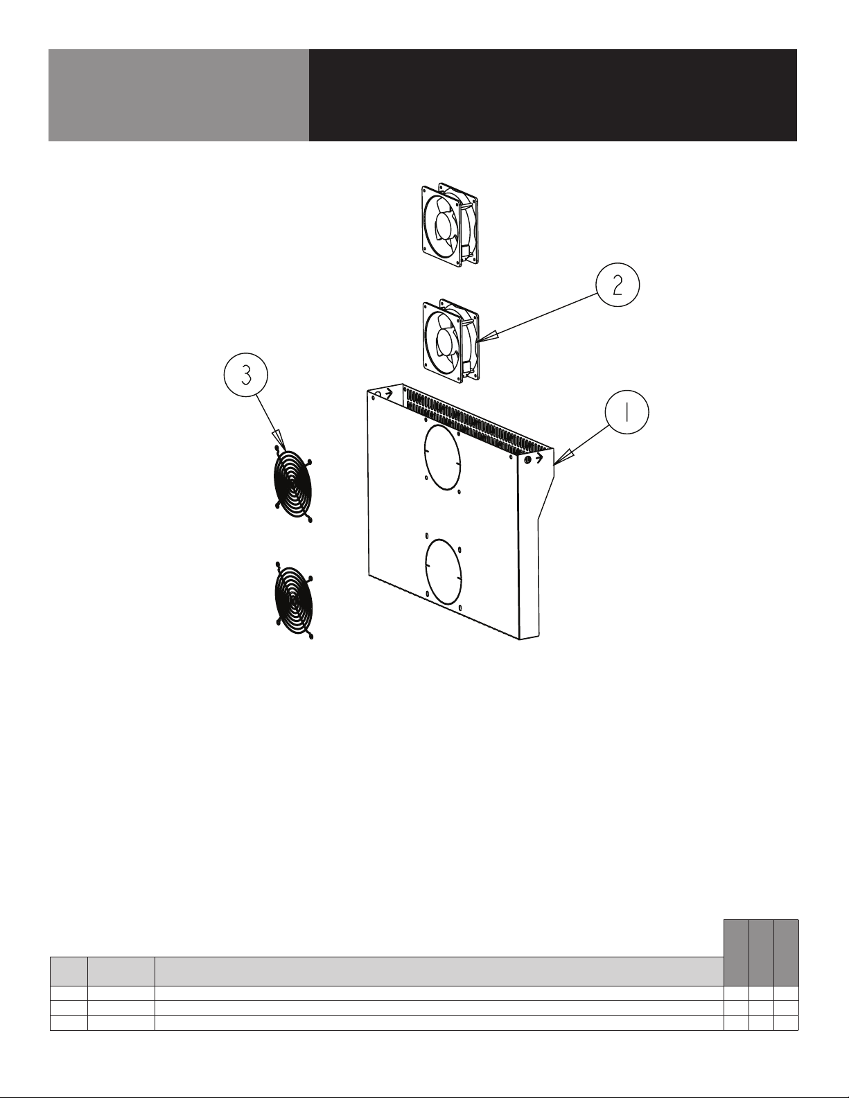
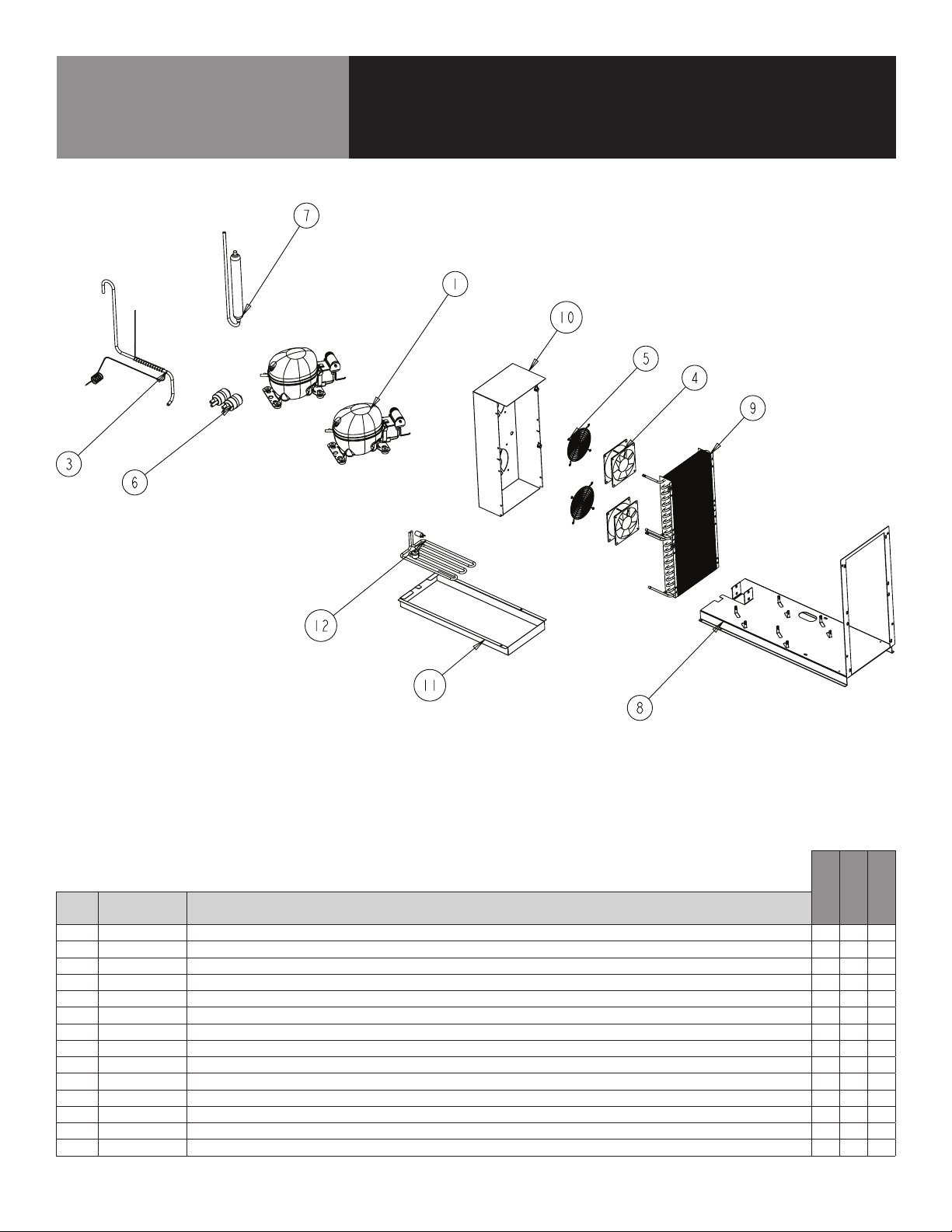
REPLACEMENT PARTS
To order parts, contact your Authorized Service Agent. Supply the model
designation, serial number, part description, part number, quantity, and when
applicable, voltage and phase.
CONTACT US
If you have questions pertaining to the content in this manual, contact Unified
Brands at 888-994-7636 or tsrandell@unifiedbrands.net.
TROUBLESHOOTING
This unit is designed to operate smoothly and efficiently if properly maintained.
However, the following is a list of checks to make in the event of a problem. Wir-
ing diagrams are found at the end of this manual. When in doubt, turn unit off
and contact service at 888-994-7636 or tsrandell@unifiedbrands.net.
SYMPTOM POSSIBLE CAUSE PROCEDURE
Unit does not run
No power to unit Plug in unit
Control in OFF position Turn controller on
Faulty control Call for service at 888-994-
7636
Unit too cold Incorrect set point Adjust control set point
Unit too warm
Door / drawer ajar Ensure door / drawer is fully
closed
Gasket torn or out of place Inspect the gasket for wear
and position
Incorrect set point Adjust control set point
Warm product introduced
to cabinet Pre-chill product 37ºF
Ice on the coil Initiate manual defrost
Unit noisy Ice on the coil Initiate manual defrost
Unit does not defrost Excessive ice on the coil Initiate manual defrost

6 OM-8000D SERIES PREP TABLES
Parts List
ELECTRICAL BOX
CALL FACTORY FOR REPLACEMENT PARTS:
888-994-7636
8148D-290
8272D-290
8396D-290
ITEM SERVICE PART DESCRIPTION
1 RP CNT1902 CONTROLLER, PROGRAMMED - TOP RAIL X X X
1A RP CNT1902 CONTROLLER, PROGRAMMED - BOTTOM RAIL X X X
1B PR CNT1807 CONTROLLER, PROGRAMMED - BASE X X X
2* RF CNT1602 SENSOR, COIL X X X
3* RF CNT1603 SENSOR, AIR XXX
4 PP STK1901 OVERLAY X X X
5 RP BOX1901 CONTROL BOX W/ COVER PLATE X X X
5A RP BOX1902 CONTROL BOX W/ COVER PLATE - - -
* = NOT SHOWN

7 OM-8000D SERIES PREP TABLES
Parts List
BASE
CALL FACTORY FOR REPLACEMENT PARTS:
888-994-7636
8148D-290
8272D-290
8396D-290
ITEM SERVICE PART DESCRIPTION
1 HD CST040HD 4" CASTERS W/ BRAKE X X X
1A HD CST041HD 4" CASTERS W/O BRAKE X X X
2 RP LVR1903 LOUVER, HINGED X X X
2A RP LVR1904 LOUVER, HINGED - - -
3 HD CTH9901 LOUVER MAGNET X X X
4 RP SHD1901 SHROUD, COIL X X X
4A RP SHD1902 SHROUD, COIL - - -
5 RP PNL1803 COVER, ACCCESS SIDE CMPR, L OR R X X X
6 HD SHL180 SHELF 22" X 25" - X X
6A HD SHL060 SHELF, 19-1/8" X 25-1/4" X - X
6B HD SHL9912 SHELF 16.15" X 25" - - -
7 HD PIN0102 SHELF SUPPORT PIN X X X
8* RP BRK0107 SHELF SUPPORT - FRT & BACK - - X
9 RP BRK0108 SHELF SUPPORT BETWEEN DOORS - X X
10* RP BRK1811 LOUVER MOUNTING HINGE BRACKET X X X
11* EL WIR1703 POWER CORD 16/3 - 9' - 90 X X X
12* HD LEG9902 6" LEG W/ BULLET FOOT X X X
* = NOT SHOWN

8 OM-8000D SERIES PREP TABLES
Parts List
FAN ASSIST
CALL FACTORY FOR REPLACEMENT PARTS:
888-994-7636
8148D-290
8272D-290
8396D-290
ITEM SERVICE PART DESCRIPTION
1 RP FAN1801 FAN ASSIST ASSY - - X
2 RF FAN1401 FAN ASSIST MOTOR - - X
3 RF FAN0702 FAN ASSIST FAN GUARD - - X
* = NOT SHOWN

9 OM-8000D SERIES PREP TABLES
Parts List
MECH COMPARTMENT -
DOUBLE COMPRESSOR
CALL FACTORY FOR REPLACEMENT PARTS:
888-994-7636
8148D-290
8272D-290
8396D-290
ITEM SERVICE PART DESCRIPTION
1 RF CMP1604 COMPRESSOR, 1/4 HP, R290, EMBRACO, 115V-60HZ X X X
2* RF CMP1604SC COMPRESSOR, START COMPONENTS X X X
3 RP CAP1802 CAP, TUBE - BOTTOM RAIL X X X
4 RF FAN0601 CONDENSER FAN X X X
5 HD GRD1610 FAN GUARD X X X
6 RF FLT251 FILTER DRIER, 1/4" DBL INLET X X X
7RF ACM1701 ACCUMULATOR X X X
8 RP MNT1803 COMPRESSOR ASM STAND (T07-1168) X X X
9 RF COI1603 CONDENSER COIL X X X
10 RP SHD1810 CONDENSER FAN SHROUD (T07-1169) X X X
11 RP CPN1803 DRAIN PAN (T07-1170) X X X
12 EL WIR274 HEATER, DRAIN PAN X X X
13* EL WIR470 POWER CORD, 16GA 2' MALE X X X
* RF CMP1702 COMPRESSOR, 1/3HP, R290 X X X
* = NOT SHOWN

10 OM-8000D SERIES PREP TABLES
Parts List
EVAPORATOR COIL
CALL FACTORY FOR REPLACEMENT PARTS:
888-994-7636
8148D-290
8272D-290
8396D-290
ITEM SERVICE PART DESCRIPTION
1 RF COI107 EVAPORATOR COIL X X X
2 RP CAP1804 CAP, TUBE - BASE - X X
2A RP CAP1803 CAP, TUBE - BASE X - -
3 RF FAN1401 FAN, EVAPORATORS X X X
4 RP DRP107 EVAPORATOR DRAIN PAN X X X
5 RP PNL107-290 SIDE, COIL, 8000N COMMON X X X
6 RP PNL108-290 BACK, COIL, 8000N COMMON X X X
7 RP PNL109-290 FRONT, COIL, 8000N COMMON X X X
8 RP SHD1811 PLATE, FAN, 8000N COMMON X X X
9 RP PNL1804 SIDE, COIL, NO PERF, 8000N COMMON X - -
* = NOT SHOWN

11 OM-8000D SERIES PREP TABLES
Parts List
DOOR ASSEMBLY
CALL FACTORY FOR REPLACEMENT PARTS:
888-994-7636
8148D-290
8272D-290
8396D-290
ITEM SERVICE PART DESCRIPTION
1 RF DOR0321 DOOR HINGED LEFT, 21" - - -
1A RF DOR0320 DOOR HINGED RIGHT, 21" - - -
1B RF DOR0323 DOOR HINGED LEFT, 24" X - X
1C RF DOR0322 DOOR HINGED RIGHT, 24" X - X
1D RF DOR0324 DOOR HINGED LEFT, 27" - X X
1E RF DOR0325 DOOR HINGED RIGHT, 27" - X X
2 IN GSK9902 GASKET, 18.5" X 24.5" PUSH IN - - -
2A IN GSK1025 GASKET, 21.75" X 24.5" PUSH IN X - X
2B IN GSK1030 GASKET, 24.5" X 24.5" PUSH IN - - X
3 RP HDL037 DOOR HANDLE X X X
4 RP HNG9900 HINGE ASSY, UNIVERSAL, LEFT/RIGHT X X X
5 HD BSH050 BUSHING, NYLON DOOR X X X
6* RP HNG025 HINGE, SPRING LOAD ASSEMBLY X X X
* = NOT SHOWN

12 OM-8000D SERIES PREP TABLES
Parts List
DRAWER ASSEMBLY
CALL FACTORY FOR REPLACEMENT PARTS:
888-994-7636
8148D-290
8272D-290
8396D-290
ITEM SERVICE PART DESCRIPTION
1 RP DRW0206 DRAWER ASSEMBLY - 21" - - -
1A RP DRW0201PT DRAWER ASSEMBLY - 24" X - X
1B RP DRW0202 DRAWER ASSEMBLY - 27" - X X
2 RP MOD050A DRAWER CARTRIDGE - 21" - - -
2A RP MOD030A DRAWER CARTRIDGE - 24" X - X
2B RP MOD029A DRAWER CARTRIDGE - 27" - X X
3 RF FRT9903 DRAWER FRONT - 21" - - -
3A RF FRT9904 DRAWER FRONT - 24" X - X
3B RF FRT9905 DRAWER FRONT - 27" - X X
4 RP FRM0301 DRAWER FRAME - 21" - - -
4A RP FRM0302 DRAWER FRAME - 24" X - X
4B RP FRM0303 DRAWER FRAME - 27" - X X
5* IN GSK9903 DRAWER GASKET - 18.75" - - -
5A* IN GSK1041 DRAWER GASKET - 21.75" X - X
5B* IN GSK1046 DRAWER GASKET - 24.75" - X X
6RP TRK05SM DRAWER TRACKS (1L & 1R) X X X
7 HD HDL130 DRAWER HANDLE X X X
8 HC BRG210 DRAWER BEARING X X X
9* FA SCW5002 DRAWER BEARING BOLT X X X
* = NOT SHOWN

13 OM-8000D SERIES PREP TABLES
Parts List
DRAIN ASSEMBLY
CALL FACTORY FOR REPLACEMENT PARTS:
888-994-7636
8148D-290
8272D-290
8396D-290
ITEM SERVICE PART DESCRIPTION
1PB VLV1803 Ball valve, 1-1/2 PVC FAMALE X X X
2PB TBG1801 TUBING, 1” VINYL, BLACK X X X
3 HD CLM1801 CLAMP, 1" OETIKER X X X
4 HD DRN1702 DRAIN, ABS, GRAY, 1.375", 1.00" NPS X 2.875" LG W/NUT & WASHER X X X
5PB ADP1802 ADAPTOR, 1" X 1" ST, INSERT X FPT, LASCO X X X
6 RP DSN0101 DRAIN SCREEN 9000 SERIES SIDEM X X X
7* HD CLP1801 CLIP, SPRING, 1” X X X
8* PB ELB1801 ELBOW, 90 DEG X X X
9* EL GRM1801 GROMMET, PUSHON, DRAIN ASSY X X X
* = NOT SHOWN

14 OM-8000D SERIES PREP TABLES
Parts List
RAIL ASSEMBLY
CALL FACTORY FOR REPLACEMENT PARTS:
888-994-7636
8148D-290
8272D-290
8396D-290
ITEM SERVICE PART DESCRIPTION
1 RP LID1902 COVER X - -
1A RP LID1904 COVER - X -
1B RP LID1906 COVER - - -
1C RP LID1908 COVER - - -
1D RP LID1910 COVER - - X
2 HD ROD100 HOOD COVER, ROD W/ SINGLE BEND X X X
2A HD ROD200 HOOD COVER, ROD W/ DOUBLE BEND X X X
3* HD PIN107 PIN, THREADED SOUTHCO XXX
4 RP BAR1325 BAR, ADAPTER 12.75" X 7/8", 8000N TPT_1AB_1 X X X
5* RP DSN001 DRAIN SCREEN, 2" X X X
6* HD PIN001 PIN, KEY PAN RAIL X X X
7* HD PIN0101 PIN, LOCATING 0.875 LENGTH X X X
8* FA NUT0403SS NUT, 1/4-20 CAP NUT 18-8 SS X X X
10 RP LID1901 COVER, HINGED PAN X - -
10A RP LID1903 COVER, HINGED PAN - X -
10B RP LID1905 COVER, HINGED PAN - - -
10C RP LID1907 COVER, HINGED PAN - - -
10D RP LID1909 COVER, HINGED PAN - - X
11* Consult Factory HOOD ASSEMBLY XXX
* = NOT SHOWN

15 OM-8000D SERIES PREP TABLES
Wiring Diagram

16 OM-8000D SERIES PREP TABLES
Service Log
Model No: Purchased From:
Serial No: Location:
Date Purchased: Date Installed:
Purchase Order No: For Service Call:
Date Maintenance Performed Performed By
This manual suits for next models
2
Table of contents
Other Randell Food Prep Table manuals

Randell
Randell 32330 User manual

Randell
Randell 9000W-290 Series User manual

Randell
Randell 31330 User manual

Randell
Randell 9302-7 User manual

Randell
Randell CR9039 User manual

Randell
Randell 9301-7 User manual

Randell
Randell 8268N User manual

Randell
Randell 8395N User manual

Randell
Randell PH48SPA-L-R User manual

Randell
Randell 9302-7 User manual