Rapid Shape RS cure User manual

Quick Start Guide
Post Curing Unit
RS cure
D cure
P cure
SHERAprint cure
3Decure

1
General
1. Overview Components
Glass bottom
The post curing unit is intended for curing
components manufactured in the DLP process.
When equipping the unit, ensure that
XXX- the components are clean and dry.
XXX- the components should not be stacked or
XXX- overlap each other.
XXX- the components should not cast shadows
XXX- over each other.
XXX- the maximum component height of 60 mm
XXX- should not be exceeded.
For proper curing of the components, observe
the specifications of the material manufacturers.
For proper operation of the post curing unit,
keep the exposure chamber clean and dust-free.
(See the cleaning instructions on page 3.)
•
•
•
•
2. General Information
For safety reasons, the unit should not be
opened during curing process.
In case the curing result deviates from the
desired result, cure again or contact Customer
Services.
Read the full operating instructions for safe work
and best results with the post curing unit.
•
•
•
Back plate Operating instructions

2
Quick Start
English
3. Preparations, Operating Mode & Start
•
•
•
•
•
•
•
•
Put on protective gloves.
Grasp the handle of the lid and lift it upwards
until it locks into the open position. (Fig. 1)
Check the vacuum seal and the glass bottom for
any contamination. If necessary, clean the
machine‘s interior according to the prescribed
cleaning steps. (Fig. 2)
(See the cleaning instructions on page 3.)
Place the components to be cured on the glass
bottom. (Fig. 3)
(See the general information on page 1.)
Close the lid. (Fig. 4)
Select the operating mode by choosing either a
job, material or customer setting (if available).
Press the start button to start the curing process.
Wait until all process steps are finished. (Fig. 5)
After the curing process is finished, check the
components for the desired result. (Fig. 6)
Figure 6Figure 5
Jobs Material Custom
D10+ capsule
2019-04-05 11:00 Upper Jaw Patient 1
D10+ capsule
2019-04-05 10:45 Upper Jaw Patient 2
D10+ capsule
2019-04-05 10:25 Upper Jaw Patient 3
Jobs Material Custom
D10+ capsule
2019-04-05 11:00 Upper Jaw Patient 1
D10+ capsule
2019-04-05 10:45 Upper Jaw Patient 2
D10+ capsule
2019-04-05 10:25 Upper Jaw Patient 3
Figure 4
Figure 1
Figure 3
Figure 2

3
Cleaning
4. Cleaning the Exposure Chamber
•
•
•
•
•
Put on protective gloves.
Open the lid. (Fig. 1)
Inspect the vacuum seal for contamination.
Remove dirt with a microfibre cloth moistened
with glass cleaner or isopropanol. (Fig. 2)
Inspect the glass bottom for contamination.
Remove dirt with a microfibre cloth moistened
with glass cleaner or isopropanol. (Fig. 3)
After cleaning, close the lid to protect the
exposure chamber from dust and dirt. (Fig. 4)
Figure 3 Figure 4
Figure 5 Figure 6
Pay Attention!
•
•
Never spray the cleaning medium directly into
the exposure chamber. This can damage the
LEDs and other components. (Fig. 5)
Never use dry wood based paper towels for
cleaning purposes. This can damage the glass
bottom and other components. (Fig. 6)
Figure 1 Figure 2

4
Maintenance
5. Exchanging the Glass Bottom
•
•
•
•
•
•
•
•
•
Open the lid.
Loosen and remove both thumb screws located
at the back plate.
Carefully remove the back plate from its
mounting position. To do this, hold the back
plate with one hand and ensure that the
connecting ribbon cable from the housing and
plate (PCB board on the back) does not
disconnect. Continue holding the back plate with
one hand and proceed with the following steps:
Remove the glass pieces on the left and right
sides from the post curing unit.
Next, remove the bottom glass piece.
Take a new glass bottom and place it inside the
post curing unit.
Re-insert the glass pieces on the left and right
sides.
Position the back plate on its mounting position
and secure it with the two thumb screws. Verify
that the connecting ribbon cable has not
become disconnected. (If so, please see instructions on
the right.)
Close the lid.
If the glass bottom cannot be cleaned anymore
or if the glass bottom is damaged, it has to be
exchanged. Dirt and cured material deflect the
UV light so that the components will not be
cured properly.
Hold the back plate with one hand and open the
clasp of the ribbon cable connection on the
sensor board.
Insert the ribbon cable into the connection point
until it sits securely against the back of it. Ensure
the contact points are facing upwards.
Secure the ribbon cable by locking the clasp
connection.
Position the back plate on its mounting position
and secure the two thumb screws again.
•
•
•
•
If the connecting ribbon cable between the
housing and the back plate has become
disconnected whilst exchanging the glass
bottom, please proceed as follows to reconnect
the cable:

Allgemein
1. Übersicht Komponenten
2. Allgemeine Informationen
Die Nachbelichtungseinheit ist für das Aushärten
von im DLP-Verfahren hergestellten Bauteilen
bestimmt.
Beim Bestücken der Einheit ist darauf zu achten,
dass die
XXX- Bauteile sauber und trocken sind.
XXX- Bauteile nicht übereinandergestapelt
XXX- werden dürfen.
XXX- Bauteile sich nicht gegenseitig abschatten
XXX- dürfen.
XXX- maximale Bauteilhöhe von 60 mm nicht
XXX- überschritten werden darf.
Für ein einwandfreies Aushärten der Bauteile,
beachten Sie bitte die Angaben der Materialher-
steller.
•
•
•
Für einen einwandfreien Betrieb der Nachbelich-
tungseinheit, halten Sie bitte die Belichtungskam-
mer frei von Staub und anderen Verunreinigun-
gen. (Siehe Reinigungs-Guidelines auf Seite 7.)
Aus Sicherheitsgründen soll die Einheit während
des Belichtungsvorgangs nicht geöffnet werden.
Sollte das Ergebnis des Belichtungsvorgangs vom
gewünschten Ergebnis abweichen, wiederholen
Sie den Vorgang oder kontaktieren Sie den
Kundendienst.
Lesen Sie die vollständige Betriebsanleitung für
ein sicheres Arbeiten und optimale Ergebnisse
mit der Nachbelichtungseinheit.
•
•
•
•
5
Glasboden Rückplatte Betriebsanleitung

6
Quick Start
3. Vorbereitungen, Betriebsart & Start
Abbildung 1
•
•
•
•
•
•
•
•
Ziehen Sie Schutzhandschuhe an.
Greifen Sie den Griff des Deckels und heben
Sie diesen nach oben, bis er in der geöffneten
Position einrastet. (Abb. 1)
Überprüfen Sie die Vakuumdichtung und den
Glasboden auf Verunreinigungen. Reinigen Sie
bei Bedarf den Innenraum der Maschine ent-
sprechend den angegebenen Reinigungs-
schritten. (Abb. 2)
(Siehe Reinigungs-Guidelines auf Seite 7.)
Legen Sie die Bauteile auf den Glasboden.
(Abb. 3) (Siehe die allgemeinen Informationen
auf Seite 5.)
Schließen Sie den Deckel. (Abb. 4)
Wählen Sie die Betriebsart, indem Sie entweder
einen Druckjob, ein Material oder eine Kunden-
einstellung (falls vorhanden) wählen.
Drücken Sie den Start-Button um den Aushärte-
vorgang zu starten. Warten Sie bis alle Prozess-
schritte beendet sind. (Abb. 5)
Überprüfen Sie nach Abschluss der Belichtung
die Bauteile auf das gewünschte Ergebnis.
(Abb. 6)
Abbildung 6Abbildung 5
Jobs Material Custom
D10+ capsule
2019-04-05 11:00 Upper Jaw Patient 1
D10+ capsule
2019-04-05 10:45 Upper Jaw Patient 2
D10+ capsule
2019-04-05 10:25 Upper Jaw Patient 3
Jobs Material Custom
D10+ capsule
2019-04-05 11:00 Upper Jaw Patient 1
D10+ capsule
2019-04-05 10:45 Upper Jaw Patient 2
D10+ capsule
2019-04-05 10:25 Upper Jaw Patient 3
Deutsch
Abbildung 2
Abbildung 3 Abbildung 4

7
Reinigung
4. Reinigen der Belichtungskammer
•
•
•
•
•
Ziehen Sie Schutzhandschuhe an.
Öffnen Sie den Deckel. (Abb. 1)
Überprüfen Sie die Vakuumdichtung auf Verun-
reinigungen. Entfernen Sie Schmutz mit einem
mit Glasreiniger oder Isopropanol angefeuchte-
ten Mikrofasertuch. (Abb. 2)
Überprüfen Sie den Glasboden auf Verunreini-
gungen. Entfernen Sie Schmutz mit einem mit
Glasreiniger oder Isopropanol angefeuchteten
Mikrofasertuch. (Abb. 3)
Schließen Sie die Maschine nach dem Reinigen
um die Belichtungskammer vor Staub und
Schmutz zu schützen. (Abb. 4)
Bitte beachten Sie!
•
•
Sprühen Sie das Reinigungsmedium niemals
direkt in die Belichtungskammer. Dies kann die
LEDs und andere Bauteile der Maschine be-
schädigen. (Abb. 5)
Verwenden Sie niemals trockene Papiertücher auf
Holzbasis zu Reinigungszwecken. Dies kann den
Glasboden und andere Bauteile der Maschine
beschädigen. (Abb. 6)
Abbildung 1 Abbildung 2
Abbildung 3 Abbildung 4
Abbildung 6Abbildung 5

8
Wartung
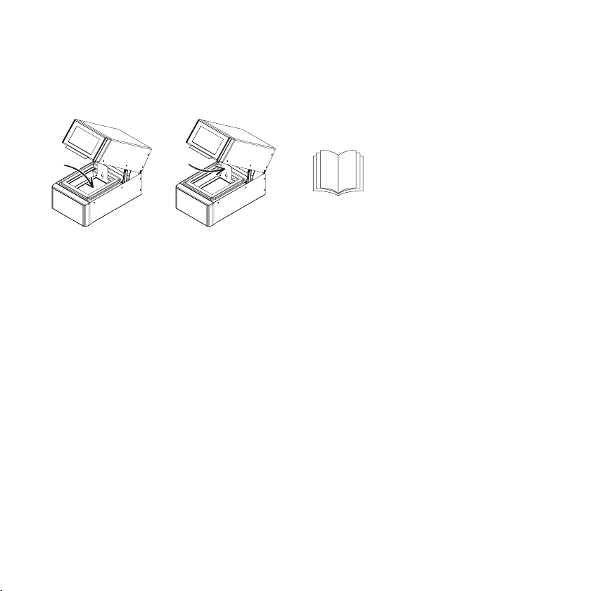
5. Wechseln des Glasbodens
•
•
•
•
•
•
•
•
•
Öffnen Sie den Deckel.
Lösen und entfernen Sie die beiden Rändel-
schrauben an der Rückplatte.
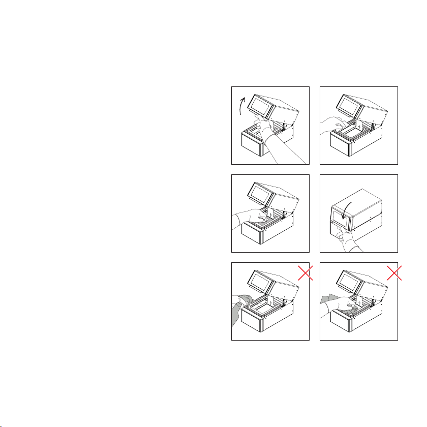
Nehmen Sie die Rückplatte vorsichtig von der
Halterung. Halten Sie dazu die Rückplatte mit
einer Hand fest und achten Sie darauf, dass sich
das Flachbandkabel von Gehäuse und Platte
(Leiterplatte auf der Rückseite) nicht löst. Halten
Sie die Rückplatte weiterhin mit einer Hand fest
und führen Sie die folgenden Schritte aus:
Entnehmen Sie die Seitengläser auf der linken
und rechten Seite aus dem Gerät.
Als nächstes entnehmen Sie den Glasboden.
Nehmen Sie einen neuen Glasboden und legen
Sie ihn in das Gerät ein.
Setzen Sie beide Seitengläser auf der linken und
rechten Seite wieder ein.
Positionieren Sie die Rückplatte zurück auf die
Halterung und befestigen Sie sie mit den beiden
Rändelschrauben. Vergewissern Sie sich, dass
das Flachbandkabel nicht abgeklemmt ist. (Wenn
ja, beachten Sie bitte die Anweisungen auf der rechten Seite.)
Schließen Sie den Deckel.
Wenn der Glasboden nicht mehr gereinigt
werden kann oder beschädigt ist, dann muss er
ausgetauscht werden. Schmutz und ausgehärtete
Materialien lenken das UV-Licht ab, so dass die
Bauteile nicht korrekt ausgehärtet werden.
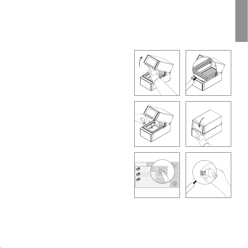
Halten Sie die Rückplatte mit einer Hand fest und
öffnen Sie den Verschluss der Flachbandkabel-
verbindung auf der Sensorplatine.
Stecken Sie das Flachbandkabel in die An-
schlussstelle, bis es fest an der Rückseite anliegt.
Stellen Sie sicher, dass die Kontaktpunkte nach
oben zeigen.
Sichern Sie das Flachbandkabel, indem Sie die
Schnappverbindung verriegeln.
Positionieren Sie die Rückplatte zurück auf die
Halterung und befestigen Sie sie mit den beiden
Rändelschrauben.
•
•
•
•
Wenn sich das Flachbandkabel zwischen Ge-
häuse und Rückplatte beim Auswechseln des
Glasbodens gelöst hat, gehen Sie bitte wie folgt
vor um das Kabel wieder anzuschließen:

http://www.rapidshape.de
Rapid Shape GmbH
Roemerstrasse 21
71296 Heimsheim, Germany
V01 2019-12-13 // DOCR000297
Other manuals for RS cure
1
This manual suits for next models
4
Table of contents
Languages:
Other Rapid Shape 3D Printer manuals