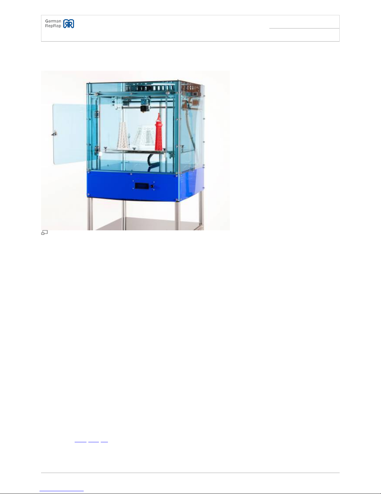
X400CE 3D Printer Manual
Seite: /245
Stand: 2015/08/28 11:55
© German RepRap GmbH /245
The X-axis ................................................................................................................................. 61
Preparation X-glider ............................................................................................................. 62
Assembly cylinder fitting screw ........................................................................................... 63
Opto end stop X ................................................................................................................... 64
Opto flag Y ........................................................................................................................... 65
Assembly X-glider ................................................................................................................ 67
Guiding rods holder .............................................................................................................. 67
Y-axis carriage ..................................................................................................................... 68
X-axis carriage ..................................................................................................................... 69
Y-axis ........................................................................................................................................ 72
Y-axis end stop .................................................................................................................... 72
Stepper motors Y-axis .......................................................................................................... 73
Idler pulley ........................................................................................................................... 74
Installing the Y-axis carriage ................................................................................................ 76
Timing belt Y-axis ................................................................................................................ 78
Timing belt X-axis ................................................................................................................ 80
The X-und Y axis version with milled aluminium parts .................................................................. 82
The X-axis ................................................................................................................................. 82
Preparation Y-carriage ......................................................................................................... 82
Opto end stop X ................................................................................................................... 84
Opto-flag Y ........................................................................................................................... 86
X-axis carriage ..................................................................................................................... 88
Y-axis ........................................................................................................................................ 91
X- and Y-axis carriage .......................................................................................................... 91
Timing belt Y-axis ................................................................................................................ 93
Timing belt X-axis ................................................................................................................ 96
The extruder ................................................................................................................................. 98
Der DD1-Extruder ..................................................................................................................... 98
Assembly of the counter bearing ......................................................................................... 98
Mounting of the counter bearing .......................................................................................... 99
Filament screw ................................................................................................................... 100
Construction of the extruder base ..................................................................................... 101
Extruder fan ....................................................................................................................... 102
Assembly of the compression spring ................................................................................. 103
DD2-Extruder ......................................................................................................................... 106
Extruder hinge ................................................................................................................... 106
Mounting extruder hinge .................................................................................................... 107
Filament screw ................................................................................................................... 109
Extruder block .................................................................................................................... 110
Extruder-fan ....................................................................................................................... 111
Mounting spring ................................................................................................................. 113
Hot-End .................................................................................................................................. 114
Thermal barrier & Nozzles ................................................................................................. 114
Hot-End Assembly .............................................................................................................. 116
Assembly Extruder with SLS-Parts .......................................................................................... 121
Installation extruder with milled aluminium parts .................................................................. 123
Electronics .................................................................................................................................. 126
Z-axis end stop ....................................................................................................................... 126
Z-axis end stop assembly ....................................................................................................... 127
Energy chain Y-axis ................................................................................................................ 129
Electronics fan grill ................................................................................................................. 130
Electronics fan ........................................................................................................................ 131
Preparing of the case connection (heated bed) ...................................................................... 133
Case connection (heated bed) ................................................................................................ 134
Base plate .............................................................................................................................. 135
ATX socket .............................................................................................................................. 136
Arduino board ......................................................................................................................... 138
Preparation of the Pololus ...................................................................................................... 139
Assembly of the cooling fins ................................................................................................... 140
Fastening of the Pololus ......................................................................................................... 141
Fastening of the RAMPS .......................................................................................................... 142
Printing bed ................................................................................................................................ 143
The heated printing bed .............................................................................................................. 145
Isolation connection cable (Heated bed) ................................................................................ 145