Raychem pyrotenax Alloy 825 User manual

MI Cable Industrial
Wiring Installation Manual
For Alloy 825 Sheath Cables

Important Safeguards
nVent RAYCHEM Pyrotenax mineral insulated
(MI) industrial wiring cables must be installed
in accordance with the requirements of national
and local codes and standards, the installation
instructions in this manual, and the customer’s
specification. Read these important safeguards and
carefully follow the installation instructions.
• Ensure the cable has been stored properly and is in
good condition prior to commencing installation.
• Always use safe working practices when installing
cables, observing OSHA and other national safety
rules.
• Store cables indoors in a clean, dry, covered area,
if possible.
• During the time that the cables are exposed and
during cable pulling activities, protect cables from
nearby or overhead work to prevent damage to the
cable sheath.
• Do not pull cables around corners that have sharp
edges, such as corners in cable trays, or other
obstructions.
• Prevent damage to cables by removing any
abrasions or sharp edges from surface of support
system.
• Damage to cables or components can cause
sustained electrical arcing or fire. Do not energize
cables that have been damaged. Damaged
cable or terminations may need to be repaired or
replaced. Damaged cable should be repaired by a
qualified person.
• When installing cables which may be exposed to
hydrocarbon flash fires, use only steel or stainless
steel in the support system.
ii | nVent.com

TABLE OF CONTENTS
1 General Information ....................................................1–2
1.1 Use of the Manual..........................................................1
1.2 Safety Guidelines ...........................................................1
1.3 Approvals........................................................................2
1.4 Warranty .........................................................................2
2 Introduction ................................................................3–4
2.1 General ...........................................................................3
2.2 Factory Terminated Cables ...........................................4
2.3 Field Terminated Cables................................................4
3 Storage and Handling................................................5–10
3.1 Storage ...........................................................................5
3.2 Handling .........................................................................7
4 Pre-Installation .......................................................11–14
4.1 Minimum Installation Temperature ............................11
4.2 Precautions ..................................................................11
4.3 Factory Terminated Cables .........................................12
4.4 Installation Equipment.................................................12
4.5 Set-Up ...........................................................................13
5 Installation..............................................................15–31
5.1 General Installation Guidelines ...................................15
5.2 Connection to Junction Boxes and
Other Equipment ..........................................................23
5.3 Installation in Hazardous Areas..................................26
5.4 Protecting the MI Cable Terminations
from Hydrocarbon Flash Fires ....................................28
5.5 Cable Terminations......................................................30
6 Testing and Commissioning ....................................32–35
6.1 Tests .............................................................................32
7 Troubleshooting Guide ............................................36–37
8 Appendixes .............................................................38–41
Appendix A: Improving Insulation Resistance ...................38
Appendix B: Cable Inspection Record ................................40
nVent.com | iii

iv | nVent.com

nVent.com | 1
1 GENERAL INFORMATION
1.1 Use of the Manual
This manual covers storage and installation of
PYROTENAX Alloy 825 Sheath MI industrial wiring cables.
It is assumed that the cables have been correctly sized
and the installation properly designed. Installers must be
trained and familiar with relevant codes and standards
and generally accepted good practice for handling and
installing power cables. For installations or situations that
are not covered in this guide, please contact nVent for
guidance.
For additional information, contact:
nVent
7433 Harwin Drive
Houston, TX 77036
USA
Tel +1.800.545.6258
Fax +1.800.527.5703
nVent.com
1.2 Safety Guidelines
The safety and reliability of an MI cable system depend on
the proper design and installation of the system and use of
proper materials for support, as well as the quality of the
cable selected. Incorrect design or installation or use of
inappropriate support materials can result in a system that
may not perform satisfactorily, and in the case of a fire-
rated system, it may not perform under fire conditions.
Install all wiring in accordance with the latest edition
of national electrical codes and standards, such as the
National Electrical Code (NEC) or Canadian Electrical Code
(CEC), and/or the Authority Having Jurisdiction and the
instructions in this manual.
• Notes are marked Note
• Important instructions are marked Important
• Warnings are marked WARNING

2 | nVent.com
1 GENERAL INFORMATION
1.3 Approvals
MI industrial wiring cables are manufactured in accordance
with international standards.
• Factory terminated cables are: cCSAus Certified
• Bulk cable is: cULus Listed and cCSAus Certified
• Field installed termination kits for bulk cable are:
cCSAus Certified
Note: ATEX certified terminations also available.
1.4 Warranty
nVent's PYROTENAX MI wiring products Limited Warranty
applies to these products. For details, see the complete
warranty on our web site at nVent.com.
Important: For the nVent warranty and agency
approvals to apply, the instructions that are included
in this manual and product packages must be followed.

nVent.com | 3
2 INTRODUCTION
2.1 General
PYROTENAX MI industrial wiring cable is manufactured
with nickel-clad copper or nickel conductors within a
robust Alloy 825 sheath, embedded in highly compacted
magnesium oxide insulation (Figure 1). This construction
and the nature of the inorganic materials used provide MI
cables with characteristics that surpass those of other
cable types without the need for additional protection such
as conduit. One of the most exceptional qualities of MI
cable is its fire resistance—the cable will not burn, support
combustion, propagate flame, or emit smoke or toxic
gases.
MI cable can be used for indoor and outdoor applications
in industrial installations. It is extensively used in
petrochemical plants where the integrity of power and
control wiring to emergency block valves and emergency
equipment must be maintained during a hydrocarbon flash
fire. The solid construction of MI cable makes it suitable
for use in hazardous areas to prevent the passage of
explosive gases. In addition, it is used in pulp and paper
plants, electricity generation plants, and in mines and
manufacturing where resistance to extreme heat and
corrosion is required. For further information on using and
installing MI cable, refer to the applicable sections of the
NEC / CEC or other national electrical codes and standards
if outside the US and Canada.
Solid nickel-clad copper
or nickel conductors
Magnesium oxide (MgO)
insulation
Alloy 825 sheath
Figure 1: MI industrial wiring cable

2 INTRODUCTION
2.2 Factory Terminated Cables
Factory terminated cables can be connected as received to
junction boxes and other equipment. The standard factory
termination utilizes the epoxy sealing compound shown in
Figure 22 on page 30. The cables are supplied with a metal
identification tag showing the cable specifications and
approvals.
2.3 Field Terminated Cables
Cables that are to be terminated in the field are supplied
with temporary heat shrinkable end caps that seal the
ends against moisture ingress. Field installed termination
kits are available with the epoxy sealing compound or
gray sealing compound shown in Section 5.5, page 30
and 31, and should be selected based on the application.
Identification tags are not supplied.
4 | nVent.com

3 STORAGE AND HANDLING
The rugged construction of PYROTENAX MI industrial
wiring cable makes it the perfect solution for all industrial
applications, no matter how extreme. However, certain
storage and handling guidelines should be followed to
minimize the possibility of damage to the cable.
3.1 Storage
To protect cables from physical damage and the
environment, inspect the cables upon receipt and observe
the following storage measures.
Initial Inspection
When the cables are received:
• Inspect the factory-applied protective covering on the
cable for evidence of shipment damage. Keep the
protective cover in place until removal is absolutely
necessary.
• Where possible, check the cable sheath for evidence of
shipment damage.
• Verify that terminations or heat shrinkable end caps are
not damaged, missing, or removed.
• Verify that factory terminated cables are correctly
labeled and have the appropriate gland connector
fittings for the intended use.
• Check the insulation resistance (IR) for the presence of
moisture in the cable using a megohmmeter (damage
to the sheath, end caps, or terminations will cause
moisture to enter the cable). See Section 6 for testing
guidelines and record the results of the tests in the
Cable Inspection Record in Appendix B. If moisture is
present, follow the instructions in Appendix A to remove
the moisture or contact nVent for guidance.
nVent.com | 5

3 STORAGE AND HANDLING
Storage Measures
• Store all cables indoors in a clean, dry location, if
possible, and protect from moisture, construction
equipment, falling objects, chemical spills, moving
vehicles, and other hazards.
• Store factory terminated cables in a manner that
prevents damage to the sealing pot and flexible tails.
• Do not remove the heat shrinkable end caps from bulk
cable until the cable is ready to be terminated.
• Do not stack coils or reels.
• Do not store coils or reels flat. Store coils upright and
reels upright on their flanges (Figure 2).
• Ensure that both ends of the cable are securely
fastened to the reel flange.
• Store reels on a firm surface, paved if possible, or on
planking to prevent reels from rotting.
Always load and store reels
upright on their flanges and
block securely.
Laying heavy reels flat
can cause damage.
Right Wrong
Figure 2: Store reels upright on flanges
6 | nVent.com

3 STORAGE AND HANDLING
3.2 Handling
Moving Coils and Reels
• Handle and install cables within suitable temperature
limits (See Section 4.1, page 11).
• Handle coils and reels utilizing equipment designed for
that purpose.
• Do not drop coils or reels from any height, particularly
from trucks or other transporting equipment.
• Lift or handle coils and cable reels in such a manner
that the lifting / handling device does not make direct
contact with the cable or its protective covering. Coils
should be placed on a skid.
• Handle reels in a manner that prevents deterioration of
and physical damage to the reel and to the cable.
• Take precautions to ensure that the flange of one reel
does not impact the cable on another reel.
Note: If a coil or reel is dropped or the protective
covering is damaged, examine the cable for damage.
Refer to Section 7 for the Troubleshooting Guide.
Damaged cables may need to be repaired or replaced.
Contact your local representative for more information.
The following lifting methods for reels are recommended
(Figure 3):
• Insert a suitable properly-secured shaft through the reel
arbor hole and lift with slings using a crane or boom-
type equipment. Use a spreader or other device to
minimize sling pressure against the reel flange.
• Move smaller, narrower reels using a forklift. Place fork
tines so that lifting pressure is on both reel flanges, not
on the cable.
nVent.com | 7

Lower reels from a truck using
a hydraulic gate, hoist or fork
lift. LOWER CAREFULLY.
Right Wrong
Reels can be hoisted with a
properly secured shaft extending
through both flanges.
Cradle both reel flanges
between fork tines.
Never drop reels.
Do not lift by a single reel
flange. Cable or reel may be
damaged.
Never allow fork tines to touch
the cable surface or reel wrap.
Figure 3: Reel handling DOs and DON’Ts
3 STORAGE AND HANDLING
8 | nVent.com

3 STORAGE AND HANDLING
• Roll reels to move them short distances and in the
direction so that the cable does not unwind (Figure 4);
this will tighten the cable windings, not loosen them.
It is recommended that surfaces over which the reels
are rolled be firm, level, and clear of debris that may
damage the cable.
Roll reel in the direction
indicated by the arrow.
Figure 4: Reel rolling
Uncoiling Cable
• Do not uncoil cable or transfer cable to another reel
prior to installation as it will become work hardened,
making it less easy to install.
• Support reel on a jack stand when uncoiling; cables
supplied in coils may be fed from a pay-off reel
(Figure 5). Have someone rotate the reel or coil to feed
the cable as it is being pulled. This will greatly ease the
handling and prevent possible twisting, bending, and
kinking.
• Use appropriate precautions when uncoiling cable (see
Section 4.2, page 11).
• Handle cable carefully during uncoiling to prevent
damage due to kinking, or bending to a radius smaller
than the minimum pulling radius (see Table 2, page 18).
• Ensure that the cable is not twisted during installation.
• Do not run over cable, drag cable over sharp objects,
or subject cable to other such treatment that could
cause damage.
nVent.com | 9

Right Wrong
Right Wrong
Reel
Coil
Figure 5: Unreeling / uncoiling cable
3 STORAGE AND HANDLING
10 | nVent.com

4 PRE-INSTALLATION
Cable installations must be preplanned to ensure a
successful installation. It is important to ensure that
personnel are properly trained and qualified for the
specific task they are performing. All applicable rules and
regulations including federal, state / provincial, local, and
municipal laws must be followed. For further information
on installing MI cables, contact nVent Technical Support,
see Section1.1.
4.1 Minimum Installation Temperature
A minimum installation temperature of −40°F (−40°C) is
recommended for MI cables.
4.2 Precautions
When installing PYROTENAX MI industrial wiring cables,
all appropriate precautions should be followed, including
OSHA and other applicable national safety regulations.
Therefore, in addition to observing standard safety
practices, observe the following:
• Take reasonable precautions to prevent damage to the
cable from severe blows with sharp instruments and
pulling over sharp objects.
• Do not pull cables around corners that have sharp
edges, such as corners in cable trays, or other
obstructions.
• Pull all cable diameters, one at a time, by hand.
• Hand feed cables around corners using large sweeping
bends.
• When changing direction from horizontal to vertical,
use properly-sized sheaves or pulleys.
• Protect exposed cables from any nearby or overhead
work that could damage the cable.
• Do not pull cables around a radius smaller than the
minimum pulling radius (see Table 2, page 18).
• Make sure all equipment used during cable installation
is in good operating condition.
For further assistance on pulling cables, contact nVent
Technical Support, see Section 1.1.
nVent.com | 11

4 PRE-INSTALLATION
4.3 Factory Terminated Cables
Prior to installation of long runs of cable, attach a short
length of PVC conduit to the factory terminated ends to
provide protection for the sealing pot and flexible tails
(Figure 6). Use 1 in (25 mm) minimum PVC pipe, or larger
if a 1 in or 1-1/4 in (25 mm or 32 mm) gland connector is
supplied. This will prevent damage to the sealing pot and
tails during installation.
1" (25 mm) min
PVC pipe
Threaded
PVC end
Reducer (from PVC pipe
to gland connector)
Gland
connector
Factory-terminated
MI cable
Figure 6: Protecting sealing pot and flexible tails
4.4 Installation Equipment
Pulling Equipment
It is recommended that all sizes of cables be hand pulled
into position, one at a time, using pulling ropes securely
attached to the cable end. When pulling cables around
corners, hand feed cables using large sweeping bends.
Mechanical pulling equipment, such as tuggers, is not
recommended.
Sheaves
Use sheaves or pulleys of the proper diameter, where
required, to avoid damage to the cable.
Pulling Rope
Use non-stretch pulling rope with a capacity large enough
to handle the force required to pull the cable.
It is recommended that the pulling rope be attached to the
cable sheath using a series of six half-hitch knots, and the
knots and rope be securely taped to the sheath to prevent
movement during the pull.
When pulling cables from a factory terminated end, ensure
that the end is protected with a short length of PVC pipe
(see Figure 6, page 12) and securely attach the pulling
rope to the cable sheath to avoid damage to the
termination.
Install cable grips, swivels, and pulling eyes, if used,
according to manufacturer’s instructions.
12 | nVent.com

4 PRE-INSTALLATION
4.5 Set-Up
Examine cable trays, trapeze support systems, and other
support systems for acceptability prior to pulling activities.
Install permanent supports properly to ensure the rigidity
of the cable tray, trapeze, or other support system so that
neither the support system nor the cable will be subjected
to damage during the pulling process.
Before installation, verify that the cable(s) can be installed
according to the designed routing and minimum bending
radius requirements.
Where it is not practical to completely remove the cable
from the reel, set up the reel using sheaves or pulleys as
shown in Figure 7 on page 14. The first sheave must be
installed at a point higher than the support system. Use
a roller at the entry and exit points of the tray / trapeze
system. The setup should ensure that the cable is not
kinked or bent beyond the minimum pulling radius (see
Table 2, page 18) or subject to excessive twisting force.
Minimize the amount of tension necessary to pull a cable
as follows:
• Pull in the proper direction. Where practical, a cable pull
should begin nearest the end having the least degrees
of bends and exit the end having the greater degrees
of bends if at all possible. Also, in vertical sections, an
upward pull is preferred.
• Minimize the number and degrees of bends the cable
is pulled around under tension. Accomplish this by
finding the straightest route possible using the least
amount of bends.
nVent.com | 13

Sheave Roller
Right Wrong
Figure 7: Reel set-up
Station experienced cable pulling observers along the
route, in contact (visually, by radio, or by phone) with the
other members of the crew.
4 PRE-INSTALLATION
14 | nVent.com

5 INSTALLATION
Following these installation instructions will consistently
produce satisfactory MI cable installations. Further
information on proper installation techniques may be
obtained by contacting nVent Technical Support, see
Section 1.1.
5.1 General Installation Guidelines
• When subject to potentially damaging abuse, protect
the cable with a metal guard such as angle iron or steel
channel.
• Metal supports, cable sheath, and other metal
enclosures for the cables must be metallically joined
together and must be connected to all boxes, fittings,
and cabinets so as to provide effective electrical
continuity.
• Ensure that you do not invalidate the listing of
enclosures or other equipment if it is necessary to cut
holes.
Moisture Absorption
The magnesium oxide insulation of MI cable is
hygroscopic and can absorb moisture when exposed to air,
causing the IR to fall. Low IR can be corrected as outlined
in Appendix A.
Expansion and Vibration
Where cables may expand or contract due to temperature
changes, or when connecting the cable to vibrating
equipment, it may be necessary to take precautions to
prevent mechanical damage to MI cable. Refer to Section
5.2, page 23 and Section 5.3, page 26 for further details.
Equipment Bonding
The sheath of Alloy 825 MI cable must be bonded to
ground, but must not be used as the equipment-to-ground
bonding conductor. For proper equipment-to-ground
bonding, use one conductor within the sheath or use a
separate equipment-to-ground bonding conductor.
Straightening and Dressing the Cable
The cable may be straightened by hand or by using a dead
blow hammer and a block of wood as shown in Figure 8.
Do not use a metal hammer as it may result in unsightly
dents that cannot be removed. Once the cable has been
installed, the use of stainless steel banding or cable
clamps to strap the cable to the tray will help dress the
cable, maintaining a neat appearance.
nVent.com | 15

Wooden
blocks
Deadblow
hammer
Figure 8: Straightening and dressing MI cable
Bending Radius
The minimum bending radius for permanent training of
PYROTENAX MI cable is shown in Table 1, although it is
recommended that bends are kept as large as possible.
Where smaller bends are necessary, a conduit bending tool
(Figure 9) may be utilized, but care must be taken not to
bend the cables to less than the minimum bending radius.
Table 1: Minimum Bending Radius for Permanent Training
Cable O.D. (outside diameter)
0.75 in (19 mm) and smaller 6 times cable diameter
Larger than 0.75 in (19 mm) 12 times cable diameter
5 INSTALLATION
16 | nVent.com
Table of contents
Other Raychem Cables And Connectors manuals

Raychem
Raychem C25-100 User manual
Raychem
Raychem Gardian W51 User manual
Raychem
Raychem nvent MI Series User manual
Raychem
Raychem JBS-100-EP User manual
Raychem
Raychem IEK-25-04 User manual
Raychem
Raychem JBM-100-E User manual
Raychem
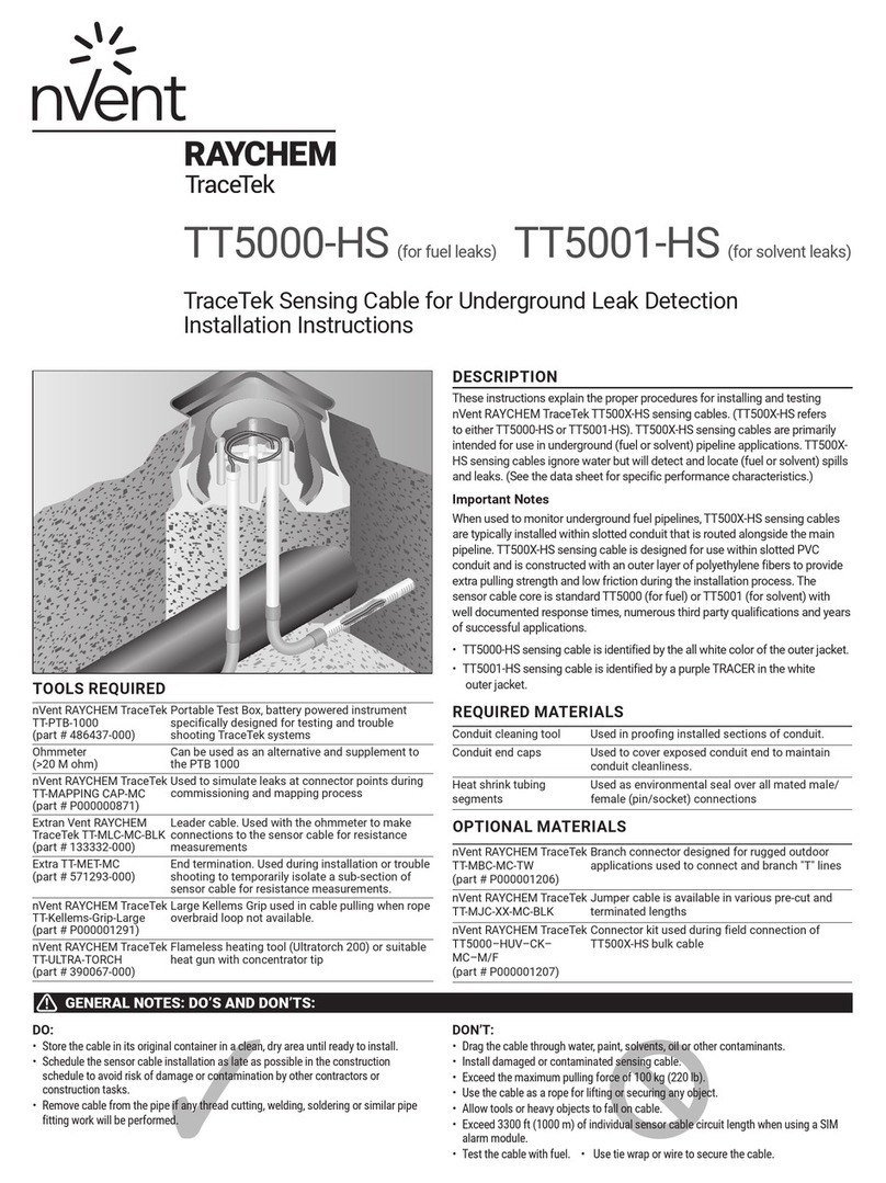
Raychem TRACETEK TT5000-HS User manual

Raychem
Raychem t-100 User manual
Raychem
Raychem RayClic-PC User manual
Raychem
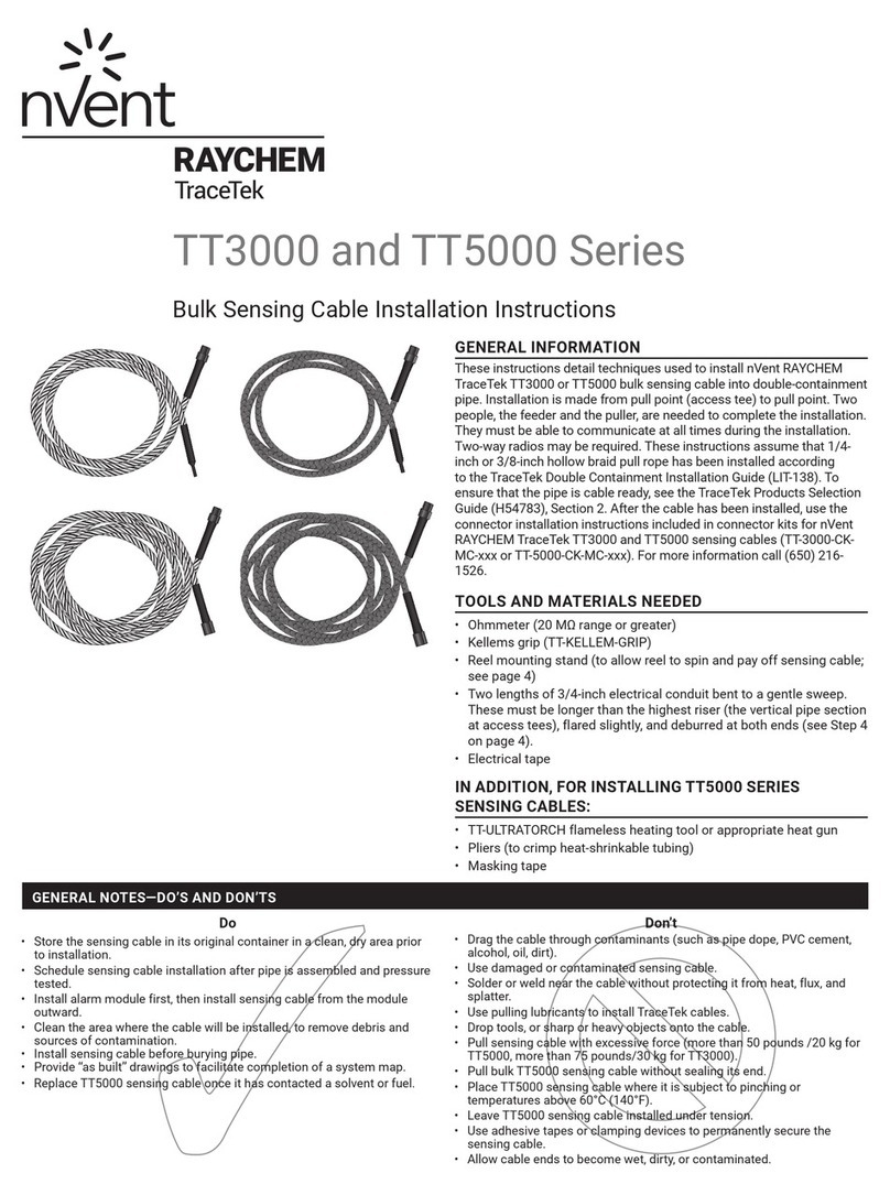
Raychem TraceTek TT3000 SERIES User manual

