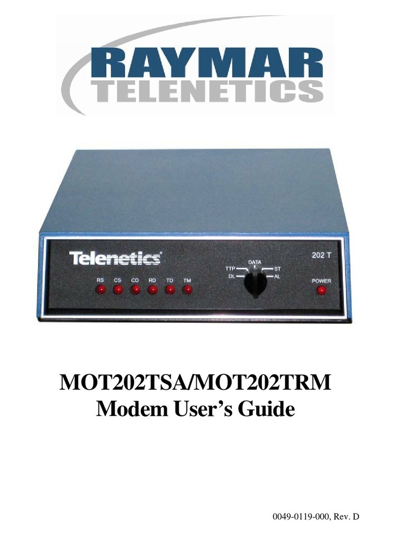
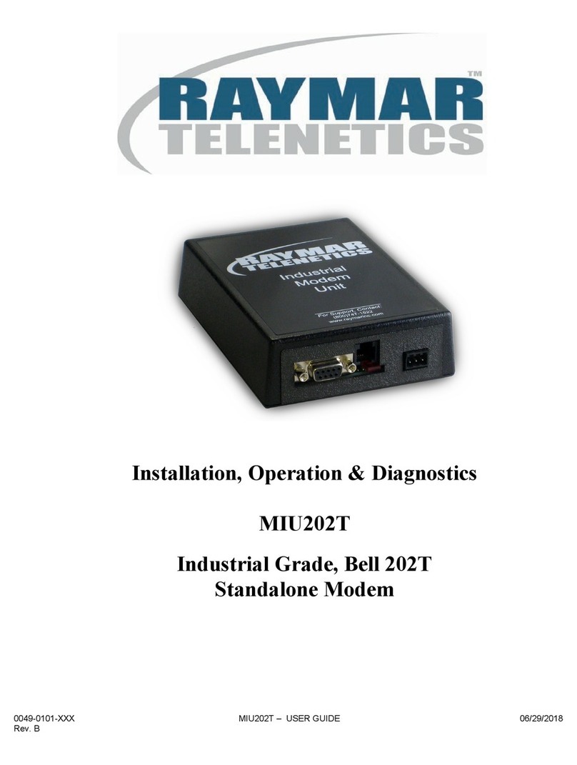
Raymar Telenetics MIU9.6FPD User manual

0049-0100-XX2 MIU9.6FPD – USERS GUIDE 06/22/2010
Rev. A
Digital Fast Poll Modem
MIU9.6FPD
USER’S GUIDE

0049-0100-XX2 MIU9.6FPD – USERS GUIDE 06/22/2010
Rev. A Page i
Raymar Information Technology, Inc.
7325 Roseville Road
Sacramento, CA 95842
800-695-1951
Fax: 916-783-1952

0049-0100-XX2 MIU9.6FPD – USERS GUIDE 06/22/2010
Rev. A Page ii
The products and programs described in this User’s Guide are licensed products
of Raymar-Telenetics. This User’s Guide contains proprietary information
protected by copyright, and this User’s Guide and all accompanying hardware
and documentation are copyrighted.
Raymar-Telenetics does not warrant that the hardware will work properly in all
environments and applications, and makes no warranty and representation,
either implied or expressed, with respect to the quality, performance,
merchantability, or fitness for a particular purpose.
Information in this User’s Guide is subject to change without notice and does not
represent a commitment on the part of Raymar-Telenetics. Raymar-Telenetics
assumes no responsibility for any inaccuracies that may be contained in this
User’s Guide.
Raymar-Telenetics makes no commitment to update or keep current the
information in this User’s Guide, and reserves the right to make changes to this
User’s Guide and/or product without notice.
No part of this manual may be reproduced or transmitted in any form or by any
means, electronic or mechanical, including photocopying, recording, or
information storage and retrieval systems, for any purpose other than the
purchaser's personal use, without the express written permission of Raymar-
Telenetics.
©Copyright 2010 Raymar Information Technology, Inc.
7325 Roseville Road
Sacramento, California 95842
Tel: 800-695-1951 Direct: +1-916-783-1951
Fax: 916-783-1952
Web site: www.raymarinc.com


0049-0100-XX2 MIU9.6FPD – USERS GUIDE 06/22/2010
Rev. A Page iii
TABLE of CONTENTS
1. INTRODUCTION................................................Page 1
2. INSTALLATION.................................................Page 6
3. APPENDIX A - TROUBLESHOOTING............Page 15
4. APPENDIX B - SPECIFICATIONS...................Page 18
5. APPENDIX C - COMPLIANCES.......................Page 23

0049-0100-XX2 MIU9.6FPD – USERS GUIDE 06/22/2010
Rev. A Page 1 of 25
CHAPTER ONE – INTRODUCTION
Congratulations for purchasing the finest industrial-grade digital, fast-poll modem available.
The Raymar-Telenetics MIU9.6FPD is a family of low-cost, state-of-the-art, 4-wire private-line
asynchronous digital fast-poll modems designed for point-to-point and multipoint data communications
over solid metallic circuits (such as pilot wires). The MIU9.6FPD provides the consistently high
performance and unsurpassed reliability demanded by today’s industrial and commercial applications. It
also offers a range of data rates from 2400 to 19,200 bps.
The MIU9.6FPD comes in low-voltage and standard-voltage models. In addition, the MIU9.6FPD is
internally surge-protected on both power and analog lines, and operates within the temperature range of
-40°C to +85°C.
The MIU9.6FPD consists of a baseboard and a communication module:
The baseboard includes the power supply regulation and surge protection.
The communication module consists of a Raymar-Telenetics Pony Express™ PE9.6FPD modem
module.
This User’s Guide is designed to let you get your MIU9.6FPD “up and running” as quickly as possible.
It contains all the information you need to configure and install your MIU9.6FPD. It also contains
troubleshooting information in the unlikely event you encounter a problem with your MIU9.6FPD.

0049-0100-XX2 MIU9.6FPD – USERS GUIDE 06/22/2010
Rev. A Page 2 of 25
MODELS
The Raymar-Telenetics MIU9.6FPD fast-poll modems are available in four models. Table 1-1
describes the features for these models.
Table 1-1. Raymar-Telenetics MIU9.6FPD
Model Number Feature Description
MIU9.6FPD-LV Single-channel standalone
modem
9.0 to 36 VDC voltage input
power supply
MIU9.6FPD/R-LV Single-channel standalone
repeater
9.0 to 36 VDC voltage input
power supply
MIU9.6FPD Single-channel standalone
modem
48 to 120 V AC/DC voltage
input power supply
MIU9.6FPD/R Single-channel standalone
repeater
48 to 120 V AC/DC voltage
input power supply
Note: In this User’s Guide, MIU9.6FPD will be used collectively to refer to all models. If
information pertains to certain models only, the appropriate model numbers in Table 1-1
will be used.

0049-0100-XX2 MIU9.6FPD – USERS GUIDE 06/22/2010
Rev. A Page 3 of 25
FEATURES
The MIU9.6FPD is specifically designed for harsh environments found in utility substations and
industrial facilities. Though functionally similar to commercial modems, the MIU9.6FPD provides
the following unique features that make it particularly well suited for utility and industrial
applications.
Packaged in a rugged, compact, non-metallic (ABS) enclosure for industrial applications.
Requires no human intervention, making it ideal for unmanned locations.
Works within an extended temperature range of -40ºC to +85ºC.
Designed with coupling transformers and opto-isolator for high-voltage isolation and common
mode noise rejection in industrial and commercial environments.
Provides surge protection superior to those of conventional commercial modems.
Accepts power from a wide range of AC and DC power supplies.
Standard industrial connectors for data, analog, and power interfaces allow reliable
interconnection to other industrial components.
2400, 4800, 9600, 19200 bps asynchronous data rates (selectable).
DIP switch configuration.
RS-232 DTE (RTU) interface.

0049-0100-XX2 MIU9.6FPD – USERS GUIDE 06/22/2010
Rev. A Page 4 of 25
APPLICATIONS
The MIU9.6FPD is designed for point-to-point and multipoint data communications. Figure 1-1
shows the MIU9.6FPD in a typical multipoint-with-repeater configuration.
Figure 1-1. Sample Multipoint-with-Repeater Configuration
There are a number of factors that can affect the MIU9.6FPD’s operation and performance.
These include:
Operating speed
Wire gauge size of the transmission line
Transmission line characteristics such as noise, interference, cross-talk, and distortions
Network configuration (point-to-point or multipoint)
Number of nodes on the network

0049-0100-XX2 MIU9.6FPD – USERS GUIDE 06/22/2010
Rev. A Page 5 of 25
Table 1-2 lists the operating distances for a single-channel MIU9.6FPD modem using 18 AWG, 24
AWG, and 26 AWG in a point-to-point configuration. Table 1-3 shows the same information for
multipoint configurations.
Table 1-2. Operating Distances for Point-to-Point Configurations
Operating DistancesData
Rate
(bps) 26 AWG 24 AWG 18 AWG
19,200 8,000 feet 10,000 feet 12,000 feet
9,600 16,000 feet 20,000 feet 25,000 feet
4,800 20,000 feet 25,000 feet 45,000 feet
2,400 34,000 feet 42,000 feet 60,000 feet
Table 1-3. Operating Distances for Multipoint Configurations
Multipoint @ 9,600 bps Operating Distance
Using 24 AWG
6 drops 17,000 feet
12 drops 15,000 feet
16 drops 12,000 feet

0049-0100-XX2 MIU9.6FPD – USERS GUIDE 06/22/2010
Rev. A Page 6 of 25
CHAPTER TWO – INSTALLATION
This chapter describes how to install the MIU9.6FPD.
Unpacking Your Hardware
Your package should include at least one MIU9.6FPD modem or repeater. If your package contents
are damaged or missing, please contact your place of purchase immediately.
Additional Items You Need
To use your MIU9.6FPD modem, you need the following additional items:
Four-wire transmission line
A communications interface to the MIU9.6FPD terminal block
An appropriate power supply:
- Models MIU9.6FPD-LV and MIU9.6FPD/R-LV accept 9.0 to 36 VDC.
- Models MIU9.6FPD and MIU9.6FPD/R accept 48 to 120 V AC/DC.
HARDWARE OVERVIEW
Figure 2-1 shows the front view of the modem. This view shows:
Two sets of configuration switches. Use the top switches to configure the modem module. The
bottom switches remain at their factory settings.
A transmission interface on the left side. The repeater has a second transmission interface on the
right side; leave the right interface unused if you will not be performing repeater applications.
Red (send data) and green (receive data) LEDs.

0049-0100-XX2 MIU9.6FPD – USERS GUIDE 06/22/2010
Rev. A Page 7 of 25
Figure 2-2 shows the back view of the modem. This view shows:
A power interface on the right side for connecting to a voltage source.
A female, 9-pin RS-232 connector on the left side, for connecting a standard DTE (RTU).
A red LED between the RS-232 connector and power interface.
Figure 2-1. Front View

0049-0100-XX2 MIU9.6FPD – USERS GUIDE 06/22/2010
Rev. A Page 8 of 25
Figure 2-2. Back View
INSTALLATION SUMMARY
The MIU9.6FPD installation involves the following steps:
1. Finding a suitable location for the modem. See the section below.
2. Configuring the modem module.
3. Connecting to a transmission line..
4. Connecting to a voltage source.
5. Optional: Connecting a DTE device.
Note: The back panel of the baseboard has four DIP switches. Leave these switches in their
factory-set positions.

0049-0100-XX2 MIU9.6FPD – USERS GUIDE 06/22/2010
Rev. A Page 9 of 25
FINDING A SUITABLE LOCATION
Its rugged enclosure and ability to work within a broad temperature range (-40oC to +85oC) make
your modem ideal for use in locations unsuitable for other modems. The location you select should
provide easy access to the back panel communications interface(s) and front panel power interface.
It should also let you view the red and green LEDs on the front panel.
Note: Raymar-Telenetics offers a rack-mount version of this modem.
Configuring the Modem Module
You configure the modem module using the six DIP switches on the modem front panel and one
jumper. Figure 2-1 shows the location of the switches and jumper.
Switch Settings
The modem has six front panel DIP switches. Table 2-1 describes the switch settings.
Note: For your convenience, the bottom of your modem has a label that summarizes the
configuration DIP switch settings.

0049-0100-XX2 MIU9.6FPD – USERS GUIDE 06/22/2010
Rev. A Page 10 of 25
Table 2-1. Switch Settings
Switch SettingsSwitch Functions
1 2 3 4 5 6
Switch 1: Anti
Streaming*
Enabled
Disabled
ON
OFF
Switch 2: Transmit
Analog (TxA) Signal
Level**
0 dBm
-10 dBm
ON
OFF
Switches 3-6: Data
Rate***
19,200 bps
9,600 bps
4,800 bps
2,400 bps
ON
OFF
OFF
OFF
OFF
ON
OFF
OFF
OFF
OFF
ON
OFF
OFF
OFF
OFF
ON
* Anti-streaming prevents slave modems from transmitting continuously
and snarling the network.
** For maximum operating distance, select 0 dBm.
*** For Switches 3 through 6, only one of these switches can be set to the
ON position.
Jumper Setting
The modem module has a jumper for selecting the impedance (see Figure 2-1). You can
access the jumper from the front panel of the PE9.6FPD.
Table 2-2 describes the jumper settings. For your convenience, the bottom of your
modem has a label that summarizes the jumper settings.

0049-0100-XX2 MIU9.6FPD – USERS GUIDE 06/22/2010
Rev. A Page 11 of 25
Table 2-2. Jumper Settings
To Select… Strap the Jumper
Between…
600 ΩRx impedance. Pins 1 and 2.
High impedance for
multipoint configurations. Pins 2 and 3. (default
setting)
Note: For point-to-point configurations, both ends
should be terminated with 600 ΩRx impedance. For
multipoint configurations, the host and the distant
modem should be terminated to 600 ΩRx impedance.
CONNECTING to a TRANSMISSION LINE
The MIU9.6FPD has a transmission line interface on the front panel (see Figure 2-1):
The single-channel standalone modem has one transmission line interface.
The repeater has two transmission line interfaces. The left interface is for connection to a
host modem and computer, while the right is for a repeater connection. If you will not be
performing repeater applications, do not use the right interface.
Each transmission line interface is a 4-wire, analog connection, where one pair is used to transmit
data (Tx+ and Tx−) and one pair is used to receive data (Rx+ and Rx−). Tables 2-3 and 2-4 show
the pin numbers and corresponding signals for the single-channel modem and repeater.
Table 2-3. Single-channel Analog Interface
This Pin Number… Corresponds to This Signal…
TB-A-pin 1 Tx+
TB-A-pin 2 Tx−
TB-A-pin 3 Rx−
TB-A-pin 4 Rx+

0049-0100-XX2 MIU9.6FPD – USERS GUIDE 06/22/2010
Rev. A Page 12 of 25
Table 2-4. Repeater Analog Interface
This Pin Number… Corresponds to This Signal…
TB-B-pin 1 Tx+
TB-B-pin 2 Tx−
TB-B-pin 3 Rx−
TB-B-pin 4 Rx+
For communications to occur, the polarity of the transmit and receive lines from one MIU9.6FPD
to another must connect as shown below:
Tx+ ⇒RX+
Tx−⇒Rx−
Rx+ ⇒Tx+
Rx−⇒Tx−
Important: Polarity of the transmission line must be followed. If connections are
reversed, no data will be received.

0049-0100-XX2 MIU9.6FPD – USERS GUIDE 06/22/2010
Rev. A Page 13 of 25
CONNECTING to a VOLTAGE SOURCE
The back panel of the MIU9.6FPD provides the power interface (see Figure 2-2). For convenience,
the MIU9.6FPD models can be powered from a wide range of power supplies. For example, the
MIU9.6FPD-LV can be powered from a 12 VDC auxiliary supply on other equipment, while the
MIU9.6FPD can be powered from a standard 120 VAC outlet.
The valid power ranges for the MIU9.6FPD vary by model. Table 2-5 lists the power ranges for
the MIU9.6FPD models. Figure 2-3 shows the connection to the MIU9.6FPD’s power interface.
Note: Before you connect to a voltage source:
Be sure the voltage source is within the permitted range in Table 2-5. Otherwise, your
MIU9.6FPD and any attached devices may be damaged.
Customer-supplied cables must be suitable for the site environmental conditions.
Screw terminals on the power interface accept 28 to 16 AWG. However, surge protection
is guaranteed only if the ground wire is greater than 18 AWG and if there is a solidly
earthed ground connection.
Be sure the power source is not controlled by a wall switch, which can be inadvertently
turned off, shutting off power to the MIU9.6FPD.
Table 2-5. Voltage Ranges
This Model… Accepts This Voltage Range…
MIU9.6FPD-LV and
MIU9.6FPD/R-LV 9.0 to 36 VDC
MIU9.6FPD and
MIU9.6FPD/R 48 to 120 V AC/DC

0049-0100-XX2 MIU9.6FPD – USERS GUIDE 06/22/2010
Rev. A Page 14 of 25
Figure 2-3. Voltage Connection to the Modem
CONNECTING an RS-232 DEVICE
The back panel of the MIU9.6FPD provides a female, 9-pin RS-232 connector (see Figure 2-2).
This connector accepts a standard connection to a DTE (RTU), such as an IBM or compatible
personal computer or VT100 terminal, that conforms to the pin assignments shown under “RS-232
(RTU) Interface”.
LEDs
The MIU9.6FPD front panel has two LEDs (see Figure 2-1):
The top LED blinks green when data is being received.
The bottom LED blinks red when data is being sent.
The MIU9.6FPD back panel has one red LED (see Figure 2-2). This LED:
Blinks once per second when power is on, but no data is being received.
Stays on continuously when data is being received.

0049-0100-XX2 MIU9.6FPD – USERS GUIDE 06/22/2010
Rev. A Page 15 of 25
APPENDIX A – TROUBLESHOOTING
In the unlikely event you encounter a problem using the MIU9.6FPD, refer to the troubleshooting
information in this appendix.
PROBLEM SOLVING
Table A-1 offers troubleshooting solutions for modem problems.
Table A-1. Troubleshooting Suggestions
If… Perform These Procedures…
The modem does not respond to the
attached DTE and all LEDs are off. Check the power supply input for your specific
model.
The modem does not receive data and
the green LED on the front panel
does not blink.
The receive line pair may be disconnected from
the modem or polarity may be reversed. Make
sure the transmission line connection to the
modem is accurate and secure.
The modem does not transmit data
and the red LED on the front panel
does not blink.
The attached terminal or DTE may not be
sending data to the modem. Verify that data is
being transmitted.
If data is being transmitted, make sure the RS-
232 cable is sound and securely connected to
the modem and terminal or DTE.
All LEDs on the modem module are
working, but the attached computer
does not work or the modem receives
data errors.
Verify all switch settings on the modem.
Make sure the modem and computer are
configured for the same operating speed.
If necessary, perform the loopback test.
The baseboard jumper and switches
have been changed from their factory
settings.
See “Baseboard Module Configuration
Settings.”

0049-0100-XX2 MIU9.6FPD – USERS GUIDE 06/22/2010
Rev. A Page 16 of 25
BASEBOARD MODULE CONFIGURATION SETTINGS
Figure A-1 shows the jumper and switch locations on the baseboard. Table A-1 shows the factory-
set jumper and switch settings for the low-voltage baseboards (Models MIU9.6FPD-LV and
MIU9.6FPD/R-LV). Table A-1 shows the factory-set jumper and switch settings for the standard-
voltage baseboards (Models MIU9.6FPD and MIU9.6FPD/R).
Do not change these factory settings.
Figure A-1. Baseboard Module Switch and Jumper Locations
Table A-1. Factory Settings for Low-Voltage Baseboard Module
This Switch/Jumper Has the Following Factory Settings…
J2 Pins 2 and 3 strapped.
Pins 6 and 7 strapped.
Pins 8 and 9 strapped.
J7 Pins 2 and 3 strapped.
J8 Pins 1 and 2 strapped.
S1 Switches 2 and 3 ON.
S3 Switches 1, 2, and 4 ON.
Switch 3 OFF.
Table of contents
Other Raymar Modem manuals

Raymar
Raymar Myriad MD9612FP User manual

Raymar
Raymar Telenetics MIU14.4L User manual

Raymar
Raymar MOT202TSA User manual

Raymar
Raymar Hidex HXII User manual

Raymar
Raymar V.32M/14.4 User manual

Raymar
Raymar HIDEX User manual

Raymar
Raymar 326X V.34 Series User manual

Raymar
Raymar MIU202T User manual

Raymar
Raymar 2.4 MIU/PowerPort Series User manual

Raymar
Raymar RMX-2 Operating instructions
Popular Modem manuals by other brands

B&B Electronics
B&B Electronics Modem datasheet

TP-Link
TP-Link TD-W8960N user guide

FiberHome
FiberHome AN5506-01-A product manual

Robustel
Robustel GoRugged M1000 MP Installation and configuration quick guide

Laipac
Laipac M2M 3350 User manual and reference guide

Ercogener
Ercogener GenPro 425e instruction sheet