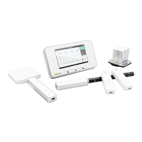
RaySafe i3 Supplement

INSTALLATION & SERVICE MANUAL
RaySafe i3

© 2017.06 Unfors RaySafe 5001104-1.1
All rights are reserved. Reproduction or transmission in whole or in part, in any form or by any means, electronic,
mechanical or otherwise, is prohibited without the prior written consent of the copyright owner.

3
RaySafe i3 Service manual – Contents
CONTENTS
ABOUT THE RAYSAFE i SYSTEM.........................................................................
Compatibility with the i system ....................................................................
PREPARATIONS .....................................................................................................
Package contents ...........................................................................................
Learn more......................................................................................................
System requirements for Dose Viewer ..........................................................
Tools required for mounting the Real-time Display.......................................
INSTALLATION.......................................................................................................
Dose Viewer....................................................................................................
Initiate a Real-time Dosimeter........................................................................
Real-time Dosimeter Rack..............................................................................
Real-Time Display .........................................................................................
CONFIGURATION ................................................................................................
User settings.................................................................................................
Admin settings ..............................................................................................
SYSTEM FUNCTION TESTS.................................................................................
Real-time Display test ..................................................................................
Dose Viewer test .........................................................................................
MEASUREMENT PERFORMANCE VERIFICATION................................................
Instruction .....................................................................................................
MAINTENANCE AND SOFTWARE UPDATE..........................................................
Dosimeter battery replacement ...................................................................
Dose Viewer software upgrade ...................................................................
Cleaning........................................................................................................
TROUBLESHOOTING...........................................................................................
TECHNICAL DATA ...............................................................................................
Real-time Dosimeter ....................................................................................
Real-time Display .........................................................................................
Real-time Dosimeter Rack ...........................................................................
Climatic conditions .......................................................................................

4
RaySafe i3 Service manual – About the RaySafe i3 System
ABOUT THE RAYSAFE i3 SYSTEM
2
1
3
4
Figure 1. 1: Dosimeter Rack, 2: Real-time Dosimeter, 3: Real-time Display, 4: Dose Viewer software.
The dosimeters measure radiation and store measurements. When a dosimeter is in range of a Real-time Display,
measurements are transferred once per second via radio and are displayed as dose rate bars low to high dose rate:
green, yellow or red. You can also have the accumulated dose displayed next to the dose rate bar.
All measurements recorded while connected to a Real-time Display are saved in the display. Tap a dosimeter user
name on the display to access the measurements.
To view the measurements stored in the dosimeter, connect the dosimeter to a computer running Dose Viewer. Dose
Viewer can also be used for changing dosimeter settings, such as displayed name and annual dose limit.
COMPATIBILITY WITH THE i2 SYSTEM
Figure 2. The RaySafe i2 dosimeter (to the right) requires a cradle to connect to a computer.
The i2 dosimeter can be used with the i3 system. The RaySafe i2 dosimeter requires the i2 cradle for connection with
Dose Viewer and Dose Manager. The i2 dosimeter has, unlike the Real-time Dosimeter, no power-saving functions, no
advanced power modes and no replaceable battery.
The Real-time Dosimeter cannot be connected directly to Dose Manager. However, Dose Manager can get dose
history from the Real-time Display via network cable or a USB memory in the i3 system. Dose Manager can be used
with the i3 system in such way.

5
RaySafe i3 Service manual – Preparations
PREPARATIONS
PACKAGE CONTENTS
NOTE: The content depends on purchased configuration.
Figure 3. Instructions for Use, Service manual, Quick Guide.
Figure 4. Real-time Display with power adapter.
Figure 5. Cables and screws, Windows software, wall mount, tie wraps, Dosimeter Rack, Real-time Dosimeters.

6
RaySafe i3 Service manual – Preparations
LEARN MORE
• Real-time Dosimeter quick guide under the lid of the dosimeter packaging
• Dose Viewer manual via the Help button in Dose Viewer
• Dose Manager manual via the Help button in Dose Manager
SYSTEM REQUIREMENTS FOR DOSE VIEWER
• Operating system: Windows XP, Windows 7, Windows 8.1 or Windows 10
• .NET 3.5 (Internet connection is required for installing on Windows 8 or 10 if you don’t have .NET 3.5)
• At least one USB port available
• At least 1 GB RAM
• At least 1 GB free disk space
• Recommended screen resolution at least 1024 x 768
TOOLS REQUIRED FOR MOUNTING THE REALTIME DISPLAY
The following tools are required for mounting the Real-time Display with VESA 75 on a wall:
• 8 mm masonry drill or one 3 mm wood drill
• cross headed screwdriver, Phillips PH2
• medium sized slotted screwdriver

7
RaySafe i3 Service manual – Installation
INSTALLATION
DOSE VIEWER
1. Check that the system requirements (on page 6) is met.
2. Log on as local administrator on the computer.
3. Insert the Dose Viewer USB memory.
4. Double click on InstallDoseViewer.exe.
5. Follow the instructions on the screen to finish the installation.
NOTE: Press Help in Dose Viewer to access the Dose Viewer manual.
TROUBLESHOOTING
If the installation procedure fails, verify that:
• the system requirements are met (on page 6).
• you are logged on as local administrator.
If there is an older version of Dose Viewer already installed, you can try uninstalling that before installing the new one.
INITIATE A REALTIME DOSIMETER
Each dosimeter needs to be initiated using Dose Viewer before use.
1. Start Dose Viewer.
2. Connect the dosimeter via USB cable to the computer running Dose Viewer.

8
RaySafe i3 Service manual – Installation
3. Open the dosimeter options window by pressing Dosimeter options and then the Settings
tab:
A
B
C
A. Verify that the computer time is correct and then synchronize the dosimeter time. Be sure to do this with all
dosimeters in a lab.
B. Set the Real-time Display Mode to Show, to make the dosimeter appear on a display.
C. Set Power Mode to On to start radio communication and dose logging.
NOTE: Power Mode On includes an automatic power saving function controlled by accelerometers.
When the dosimeter is stationary for 3 minutes, it enters power save (no dose logging, no radio
communication). The dosimeter wakes up when moved again. If the dosimeter is stationary
positioned, not worn by a person, turn o the automatic power saving by selecting Advanced:
Always on.

9
RaySafe i3 Service manual – Installation
4. Press Information:
A
A
B
B
B
C
A. Set Full Name and Display Name. The Display Name appears in the online view on the Real-time Display. The
Full Name is visible in the dose history views on the Real-time Display and in Dose Viewer.
B. Change Dosimeter Position, Clinical Role and Annual Dose Limit if desired. These settings do not aect the
dose registration.
C. Select Displayed Symbol and insert a corresponding inlay under the plastic shield on the front of the
dosimeter. Tip: Write on the inlay.
4. Press Save and disconnect the dosimeter.
NOTE: Always power OFF the dosimeter before air transport, to make sure that the radio communication is
completely turned o.
REALTIME DOSIMETER RACK
A Real-time Dosimeter rack provides room for 5 dosimeters. Mount it on a wall with easy access, for example near
storage of radiation protection garment.
1. Mount the rack with 2 screws to the wall.
2. Attach the dosimeters.

10
RaySafe i3 Service manual – Installation
3. Mount the supplied quick guide sticker above the rack.
REALTIME DISPLAY
21 3
4
Figure 6. Interfaces (back side of the Real-time Display): 1: 12 V DC, 2: Ethernet, 3: USB, 4: VESA 75
MOUNT THE REALTIME DISPLAY
NOTE: In a setup with multiple Real-time Displays, there should only be one per room.
NOTE: For other mounting options than VESA 75 on wall, contact your RaySafe representative.
The wall mounting parts for the Real-time Display:
• one VESA 75 wall mounting kit
• separate screws and washers for mounting the VESA 75 to the Real-time Display
Mount the Real-time Display on a wall:
1. Attach the VESA 75 Real-time Display mounting plate to the Real-time Display using the screws and washers
provided separately (not in the VESA 75 wall mounting kit). Use 8 washers, one on each side of the VESA plate for
each screw.
2. Follow the instructions included in the VESA 75 wall mounting kit for attaching the VESA to the wall.
3. Attach the Real-time Display to the wall mounted part.

11
RaySafe i3 Service manual – Installation
4. Connect the power adapter to the Real-time Display and to an electrical outlet. The Real-time Display will turn
on and your dosimeters will show up on the screen. The first time a dosimeter connects to a certain Real-time
Display, the detection process can take up to three minutes.
5. As soon as the dosimeters show up on the display, the system is ready to use!
Figure 7. Online view on Real-time Display
The following chapters describe optional configurations and tests.
CAUTION: The electrical outlet socket shall be easily accessible, for security reasons.
ETHERNET CONNECTION OPTIONAL
Dose Manager can be purchases separately to be used with RaySafe i3. The Ethernet interface is used together with
the Dose Manager application only.
Connect the Real-time Display to the hospital network:
1. Connect an Ethernet cable (not included in the package) to the hospital’s network.
2. Connect the Ethernet cable to the Ethernet connector at the back of the Real-time Display.
3. Configure the network connection, see “Admin settings 3/4: Network.” on page 14.

12
RaySafe i3 Service manual – Configuration
CONFIGURATION
The Real-time Display is delivered with the required software installed. The default settings are usually suitable. This
chapter will guide you through the settings screens.
Figure 8. Online view with settings button highlighted.
Tap the cogwheel in the upper left corner of the online view to access the settings.
NOTE: Some changes require a restart to take eect. Disconnect and reconnect the power cord to restart
the Real-time Display.

13
RaySafe i3 Service manual – Configuration
USER SETTINGS
Figure 9. User settings 1/1: Backlight.
Tap the + or - buttons (Figure 9) to adjust the backlight level.
ADMIN SETTINGS
A
B
C
Figure 10. Admin settings 1/4: Identity and contact, and notification area in personal dose overview.
The Real-time Display Name and Location (A in Figure 10) is only applicable in use together with Dose Manager
(optional Windows software), to be able to download dose data from the Real-time Display to Dose Manager.
The Service Contact Name and Number (B in Figure 10) appears in the notification area (C in Figure 10), on the left
side of the personal dose overview (accessed by tapping a dosimeter name), only when service is required.

14
RaySafe i3 Service manual – Configuration
Figure 11. Admin settings 2/4: Reserved slots.
The admin and system settings menu consists of several screens. Tap the arrows in the lower right corner to access
the other screens.
You can Reserve slots (rows) (Figure 11) in the online view for dosimeters with a certain clinical role set. For example,
if you have reserved three slots for doctors and there is only one doctor within range, there will be two empty rows
before the first nurse is displayed. Auto is default. The dosimeters will appear in the order they are detected by the
Real-time Display, sorted by clinical role: doctor, nurse, technician, other.
Figure 12. Admin settings 3/4: Network.
Network setup (Figure 12) is only useful if your Real-time Display is connected to Ethernet and you have Dose
Manager installed in your system. Contact your local IT department for help with these settings.
Changes of the network settings requires a restart to take eect.

15
RaySafe i3 Service manual – Configuration
Figure 13. Admin settings 4/4: Time and date.
You can manage Daylight Saving Time manually, or by selecting a region for your Time Zone (Figure 13). The list of
regions is updated according to the selected time zone.
A
B
C
D
E
Figure 14. System settings 1/3: Touch screen and dose settings.
Uncheck the box Touch Screen Enabled (A in Figure 14) to turn o the possibility to tap on a dosimeter row to access
dose history on the Real-time Display. The settings menu is however always accessible.
You can copy dose history from the Real-time Display to a USB memory. Insert the memory at the back of the Real-
time Display (see Figure 6 on page 10). Press the button Sync to USB (B in Figure 14) to start writing to the memory.
If you want to delete all Dose History from the Real-time Display, press the Reset button (B in Figure 14). This reset will
not aect the dose history stored in the dosimeters.
The Accumulated Procedure Dose (C in Figure 14) is shown to the right of each dose rate bar in the online view, when
activated. Reset the dose value with a tap on the Reset button in the lower right corner of the online view (E in Figure
14).
Conversion factor for the units (D in Figure 14) is 1 Sv = 100 rem.

16
RaySafe i3 Service manual – Configuration
Figure 15. System settings 2/3: Communication range.
If you experience problems with the communication between dosimeter and display, try changing the range setting
(Figure 15):
• If other dosimeters than the desired show up on the display, select Nearby.
• If dosimeters do not show up on any display, select Maximum Range.
Figure 16. System settings 3/3: Language.
Select language (Figure 16) for the Real-time Display user interface. This setting requires a restart to take eect.

17
RaySafe i3 Service manual – System function tests
SYSTEM FUNCTION TESTS
We recommend these tests in order to verify the correct installation and configuration of the RaySafe i3 system.
REALTIME DISPLAY TEST
ONLINE VIEW TEST
Follow the instructions below to verify that the dosimeter appears in the Real-time Display:
1. Check that the dosimeter appears in the display’s online view.
2. Expose the dosimeter to scattered radiation by placing the dosimeter outside the primary beam, close to a
phantom which is placed in the X-ray field. Verify that the Real-time Display shows a dose rate bar instantaneously,
updating once per second (Figure 17).
Figure 17. The Real-time Display online view.
DOSE VIEWER TEST
Follow the instructions below to verify that Dose Viewer detects the dosimeter:
1. Connect the dosimeter to a computer running Dose Viewer.
2. Dose Viewer will detect the dosimeter within a few seconds. Ensure that dosimeter information and dose history
is presented in the main window (Figure 18).

18
RaySafe i3 Service manual – System function tests
Figure 18. Dose Viewer with a dosimeter connected.
COMMUNICATION RANGE TEST
Follow the instructions below to verify the function of an environment with several Real-time Displays installed.
Check that the dosimeter communication range configuration is correctly tuned, that is, dosimeters currently not in
use shall not appear on the Real-time Display’s online view, but will appear when they approach the display.
1. Position a dosimeter near Real-time Display A.
2. Visually check that the dosimeter is shown on Real-time Display A.
3. Move the dosimeter within range of Real-time Display B.
4. Visually check that the dosimeter appears on Real-time Display Bwithin 30 seconds within range.
5. Put the dosimeter in a rack and verify that it disappears from all displays within 3 minutes.
See also “System settings 2/3: Communication range.” on page 16. If anything fails in this test, see
“Troubleshooting” on page 21.§

19
RaySafe i3 Service manual – Measurement performance verification
MEASUREMENT PERFORMANCE VERIFICATION
The dosimeter is delivered calibrated, with no need for re-calibration during its lifetime. See the radiological
specification in the accompanying Instructions for Use. If you want to control the measurement accuracy, we
recommend the following arrangement.
The purpose of this test is to verify the measurement performance of dosimeters using scattered radiation from
diagnostic X-ray units.
CAUTION: Do not expose yourself to X-ray radiation.
Required equipment:
• Two PMMA phantoms or other scattering material.
• Dosimeters for test
• Real-time Display, for dosimeter readings
INSTRUCTION
1. Place one of the phantoms (simulating the patient) on the patient support. Use a large phantom or a bucket filled
with water.
2. Place the other phantom (simulating the sta) at the same height, but 1.5 m away from the first one.
3. Place the dosimeter at the sta phantom, centered on the side facing the patient phantom. Test one dosimeter at
a time.
4. Expose with a field fully covering the patient phantom, at 80 kVp set, 4 mA, for 60 s. Adjust the mA to get a dose
rate of above 1 mSv/h. The dose rate can also be increased by placing a larger (or several) phantom(s) to simulate
the patient.
5. Note the dose rate from the Real-time Display. Repeat steps 1 – 4 with the dosimeters you want to compare.
1.
2.
3.
4.
Figure 19. Performance verification arrangement. 1. Patient phantom. 2. Sta phantom. 3. Dosimeter. 4. X-ray field.
NOTE: Radiologic specification in Instructions for Use (separate document).

20
RaySafe i3 Service manual – Maintenance and Software Update
MAINTENANCE AND SOFTWARE UPDATE
DOSIMETER BATTERY REPLACEMENT
When a red LED flashes on the side of the dosimeter, the battery needs to be replaced. You need a Phillips
screwdriver (PH1) and a battery (CR2450) for this.
NOTE: Make sure that the dosimeter is not connected to a computer with a USB cable while replacing the
battery.
1. Remove the screws on both sides of the dosimeter clip.
2. Remove the battery cover.
3. Take out the battery by carefully bending with for example the plastic clip under the battery at the top side of the
dosimeter.
4. Wait for 5 seconds before inserting the new battery, to make sure that the dosimeter registers that a new battery
is inserted.
5. Put on the cover and the clip (optional) and insert the screws carefully (max 0.15 Nm torque), to avoid damage on
the screw threads.
Check that the dosimeter appears on a Real-time Display again.
DOSE VIEWER SOFTWARE UPGRADE
Follow the installation instructions in section “Dose Viewer” on page 7 to upgrade Dose Viewer.
NOTE: Configuration from a previous version of the Dose Viewer software will remain unaected by the
software update.
REALTIME DISPLAY TOUCH SCREEN CALIBRATION
If the touch screen does not respond correctly to user interaction, a touch screen calibration may be needed.
1. Tap on the welcome screen that appears during Real-time Display startup. (Restart by disconnecting and
reconnecting the power cord.)
2. Follow the instructions on the screen to perform the calibration.
CLEANING
For cleaning of dosimeter and display, use a damp cloth and mild detergent.
Other manuals for i3
5
Table of contents
Other RaySafe Measuring Instrument manuals
Popular Measuring Instrument manuals by other brands

Seres OL
Seres OL TOPAZ Total Hardness Operator's manual

Analog Devices
Analog Devices ADE9000 Technical reference manual

PCB Piezotronics
PCB Piezotronics J356A03/NC Installation and operating manual

Bedrock
Bedrock AM100 operating manual

Keithley
Keithley 660A instruction manual

Kobold
Kobold DON Series operating instructions