RCA 25425 User manual

4-Line Intercom Speakerphone
with Answering System and Caller ID
User’s Guide
Please read this manual
before operating product
for the first time.
Model 25425
Quick
Guide
on Pgs.
6-14

2
Important Information
NOTICE: This product meets the applicable Industry Canada technical specifications.
Operation is subject to the following two conditions: (1) This device may not cause inter-
ference, and (2) This device must accept any interference, including interference that may
cause undesired operation of the device.
The equipment must be installed using an acceptable method of connection. The customer
should be aware that compliance with the above conditions may not prevent degradation
of service in some situations.
Repairs to certified equipment should be made by an authorized Canadian maintenance
facility designated by the supplier. Any repairs or alterations made by the user to this
equipment, or equipment malfunctions, may give the telecommunications company cause
to request the user to disconnect the equipment.
Users should ensure for their own protection that the electrical ground connections of the
power utility, telephone lines and internal metallic water pipe systems, if present, are con-
nected together. This precaution may be particularly important in rural areas.
CAUTION: Users should not attempt to make such connections themselves, but should con-
tact the appropriate electric inspection authority, or electrician, as appropriate.
NOTES: This equipment may not be used on coin service provided by the telephone com-
pany.
Interference Information
This equipment generates and uses radio frequency energy which may interfere with
residential radio and television reception if not properly installed and used in accordance
with instructions contained in this manual. Reasonable protection against such interfer-
ence is ensured, although there is no guarantee this will not occur in a given installation.
If interference is suspected and verified by switching this equipment on and off, the user
is encouraged to try to correct the interference by one or more of the following measures:
Reorient the radio/television receiver’s antenna, relocate the equipment with respect to
the receiver, plug the equipment and receiver into separate circuit outlets. The user may
also wish to consult a qualified radio/television technician for additional suggestions. This
equipment has been fully tested and complies with all limits for Class B computing devices
pursuant to part 15 FCC Rules and Regulations.
Important Information

3
Important Information
Telephone Network Information
Should your equipment cause trouble on your line which may harm the telephone network,
the telephone company, where practicable, may notify you that temporary discontinuance
of service may be required. Where prior notice is not practicable and the circumstances
warrant such action, the telephone company may temporarily discontinue service immedi-
ately.
The telephone company may make changes in its communications facilities, equipment,
operations or procedures where such action is required in the operation of its business.
If these changes are expected to affect the use or performance of your telephone equip-
ment, the telephone company will likely give you adequate notice to allow you to maintain
uninterrupted service.
Notice must be given to the telephone company upon termination of your telephone from
your line.
REN Number
On the bottom of this equipment is a label indicating, among other information, the Ringer
Equivalence Number (REN) for the equipment.
The REN is useful in determining the number of devices you may connect to your tele-
phone line and still have all of these devices ring when your telephone number is called.
In most (but not all) areas, the sum of the RENs of all devices connected to one line should
not exceed 5. To be certain of the number of devices you may connect to your line as
determined by the REN, you should contact your local telephone company.
REN Number is located on the cabinet bottom.
FCC RF Radiation Exposure Statement
This equipment complies with FCC RF radiation exposure limits set forth for an
uncontrolled environment. This equipment should be installed and operated with a
minimum distance of 20 centimeters between the radiator and your body. This transmitter
must not be co-located or operated in conjunction with any other antenna or transmitter.”
For body worn operation, this phone has been tested and meets the FCC RF exposure
guidelines when used with the belt clip supplied with this product. Use of other
accessories may not ensure compliance with FCC RF exposure guidelines.
Licensing
Licensed under US Patent 6,427,009.
Hearing Aid Compatibility
This telephone system meets FCC standards for Hearing Aid Compatibility.

4
Important InformatIon ............................................. 2
Interference InformatIon.......................................... 2
telephone network InformatIon ............................... 3
ren number........................................................... 3
fcc rf radIatIon exposure statement ..................... 3
lIcensIng ................................................................. 3
hearIng aId compatIbIlIty ........................................ 3
IntroductIon ............................................................ 4
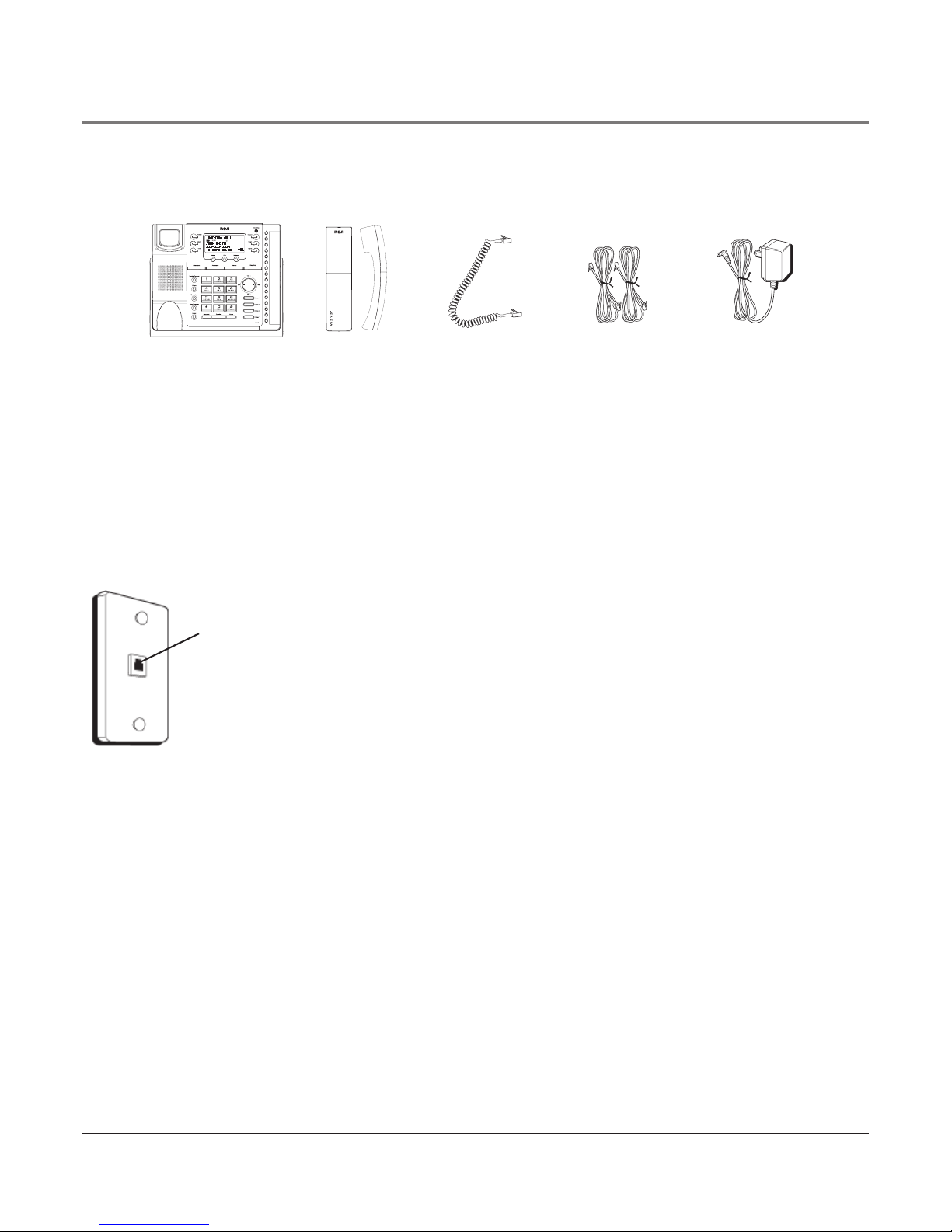
parts checklIst........................................................ 7
telephone Jack requIrements.................................... 7
Important InstallatIon InformatIon........................... 8
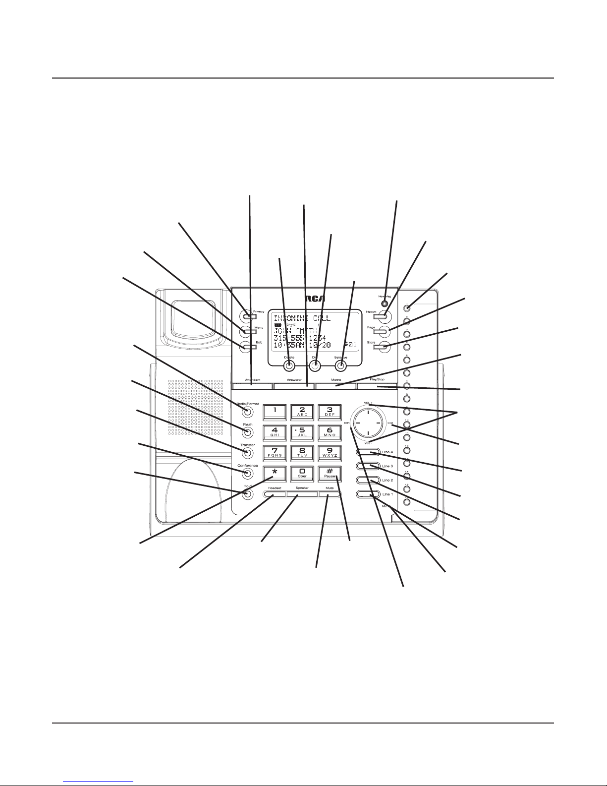
base layout............................................................. 9
Important InstallatIon guIdelInes ........................... 10
InstallIng the phone .............................................. 11
data port .............................................................13
system VerIfIcatIon................................................14
other system phones.............................................14
Answering system .....................................................14
Auto AttendAnt .......................................................... 15
programmIng the telephone ...................................15
LAnguAge .....................................................................15
VoLume......................................................................... 15
ringer VoLume ...................................................... 15
speAkerphone, hAndset, And heAdset VoLume .... 15
ringer tone................................................................. 16
priority Line ................................................................ 16
deLAy ring................................................................... 17
phone id ..................................................................... 17
phone nAme ................................................................ 18
intercom Auto Answer............................................... 18
FLAsh time ................................................................... 18
cALL ALert tone .......................................................... 19
nounknown/BLocked................................................ 19
dispLAy contrAst......................................................... 20
LocAL AreA code......................................................... 20
regionAL AreA codes.................................................. 20
mAnuALLy setting the time And dAte......................... 21
hour FormAt............................................................... 22
restoring the deFAuLt settings.................................. 22
programmIng the answerIng system ......................22
pickup deLAy................................................................22
messAge Length ..........................................................23
cALL screening............................................................23
messAge interrupt ......................................................24
remote pAssword........................................................24
mAiLBox ....................................................................... 24
programmIng the auto attendant .......................... 25
Auto AttendAnt pickup deLAy .................................... 25
set dAy time For Auto AttendAnt.............................. 26
set night time For Auto AttendAnt .......................... 26
set night time on / oFF.......................................... 27
set weekend greeting................................................ 27
set VALid id ................................................................ 28
basIc operatIon ..................................................... 28
mAking cALLs with the hAndset ................................ 28
mAking cALLs with the speAkerphone........................ 28
mAking cALLs with the optionAL heAdset ................. 29
pre-diALing.................................................................. 29
Answering cALLs......................................................... 29
switching Between the speAkerphone, hAndset, And
heAdset .................................................................. 30
mute ............................................................................ 30
donot disturB........................................................... 30
hoLd............................................................................. 31
pLAcing AcALL on hoLd ....................................... 31
reLeAsing AcALL From hoLd ................................ 31
FLAsh............................................................................ 31
rediAL........................................................................... 31
reViewing the rediAL numBers................................... 31
trAnsFerring AcALL to Another stAtion................... 32
receiVing AtrAnsFerred cALL From Another
stAtion ................................................................... 32
priVAcy......................................................................... 32
proViding priVAcy ................................................. 32
conFerence cALLs........................................................ 33
Intercom calls ..................................................... 34
one-touch intercom .................................................. 34
Answering An intercom cALL..................................... 34
intercom hoLd ............................................................ 34
intercom conFerence cALLs........................................ 35
pAging ALL stAtions.................................................... 35
caller Id .............................................................. 36
summAry screen......................................................... 36
receiVing And storing cid records.......................... 36
reViewing cid records........................................ 36
sAVing Acid record to the intercom/memory Log
or to phone Book memory .................................. 36
deLeting Acid record......................................... 37
deLeting ALL cALL records................................... 37
diALing BAck ......................................................... 37
Table of Contents

5
SEE MARKING ON BOTTOM / BACK OF PRODUCT
RISKOFELECTRICSHOCK
DONOTOPEN
WARNING: TO
PREVENT FIRE OR
ELECTRICAL SHOCK
HAZARD, DO NOT
EXPOSETHIS
PRODUCT TO RAIN
OR MOISTURE.
THE LIGHTNING
FLASH AND ARROW
HEAD WITHIN THE
TRIANGLE IS A
WARNING SIGN
ALERTING YOU OF
“DANGEROUS
VOLTAGE” INSIDE
THE PRODUCT.
CAUTION: TO REDUCE THE
RISK OF ELECTRIC SHOCK, DO
NOT REMOVE COVER (OR
BACK). NO USER
SERVICEABLE PARTS INSIDE.
REFER SERVICING TO
QUALIFIED SERVICE
PERSONNEL.
THE EXCLAMATION
POINT WITHIN THE
TRIANGLE IS A
WARNING SIGN
ALERTING YOU OF
IMPORTANT
INSTRUCTIONS
ACCOMPANYING
THE PRODUCT.
CAUTION:
Table of Contents
iFyou progrAmmed your LocAL AreA code .............37
iFyou did not progrAm your LocAL AreA code.....37
cALL wAiting cALLer id..............................................38
memory Log And phone Book (directory)
memory..................................................................38
storing AnumBer And nAme in memory ...........38
reViewing phone Book (directory) memory ......39
reViewing the intercom/memory Log
(memory LocAtion).................................................39
editing AnAme or numBer stored in phone Book
(directory) memory .............................................39
editing AnAme or numBer stored in the intercom/
memory Log (memory LocAtion) ........................39
storing the LAst numBer diALed .........................40
storing ApAuse in memory.................................40
diALing Astored numBer.....................................40
memory deLete/cLeAr...........................................40
cLeAr ALL memories .............................................41
chAin diALing........................................................41
answerIng system .................................................42
Answering system ......................................................42
turning the Answering system on/oFF....................42
recording Agreeting .................................................42
pLAyBAck And erAsing Agreeting ..............................42
recording incoming messAges ..................................43
monitoring incoming cALLs .......................................43
memo recording ........................................................43
two-wAy recording ..................................................43
messAge pLAyBAck.......................................................44
deLeting messAges......................................................44
Accessing the Answering system From Another
LocAtion .................................................................44
connecting with the Answering system ...................44
toLL sAVer operAtion..................................................45
auto attendant.....................................................45
turn Auto AttendAnt on/oFF....................................45
Auto AttendAnt sequence For cALLers ......................46
recording Auto AttendAnt greetings .......................46
pLAyBAck And erAsing Auto AttendAnt greetings ....47
using muLtipLe Auto AttendAnts...............................48
dIsplay messages ..................................................48
operatIon bybattery.............................................49
operatIon wIthout power.......................................49
cordless phone optIon ..........................................49
troubleshootIng guIde ...........................................50
general product care ...........................................51
serVIce ..................................................................52
accessory InformatIon...........................................53
Index.....................................................................54

6
Connections & Setup
Introduction
CAUTION: When using telephone equipment, there are basic safety instructions that
should always be followed. Refer to the IMPORTANT SAFETY INSTRUCTIONS provided
with this product and save them for future reference.
Your Four-Line Speakerphone is a full-featured phone ideally suited for home-office use.
It is designed to receive calls on up to four incoming telephone lines and to serve up to 16
station users. Your phone features 16 memory locations, 94 phone book memories, hold,
conference call, intercom, call transfer, Caller ID display, and speakerphone capabilities. It
also features an Auto Attendant function, which will pick up and redirect incoming calls to
other extensions in the system per the caller’s input. It is possible to enhance your phone
to a cordless feature with the additional purchase of the H5401 accessory handset and
module.
This telephone is designed to be simple to use, however, you can reach its full potential
more quickly by taking a few minutes to read this user’s guide.
IMPORTANT: In order to use all of the Caller ID features of this telephone, you must subscribe
to two separate services available from your local telephone company: the standard Name/
Number Caller ID Service to know who is calling when the phone rings and Call Waiting
Caller ID Service to know who is calling while you are on the phone.

7
Connections & Setup
Parts Checklist
Make sure your package includes the following items:
Telephone Jack Requirements
To use this phone, you will need an RJ11C (for a single line) or a RJ14C (for two lines) type
modular phone jack, which might look like the one pictured here, installed in your home
or office. If you don’t have either modular jack, call your local phone company to find out
how to get one installed.
VERY IMPORTANT: In order to achieve full system operation (i.e.
intercom, page, etc.), Line 1 must be connected and must be
common to all phones connected to the system. Only other 25423,
25424, 25425, 25413, 25414, 25415, 25403 and 25404 models are
compatible for full system operation. Connecting phones other
than the 25423, 25424, 25425, 25413, 25414, 25415, 25403 and
25404 to Line 1 may inhibit the intercom and paging operations.
For proper operation of intercom, page function, etc., DO NOT
connect a DSL modem to Line 1.
To transfer a call from one station to another, the two stations
should be connected to the same line.
Base Handset Handset cord Line cords AC power
adaptor
Modular
telephone line
jack
Wall plate

8
Connections & Setup
Important Installation Information
• Never install telephone wiring during a lightning storm.
• Never install telephone jacks in wet locations unless the jack is specifically designed for
wet locations.
• Never touch non-insulated telephone wires or terminals, unless the telephone line is
disconnected from the network.
• Use caution when installing or modifying telephone lines.
• Temporarily disconnect any equipment connected to the phone such as faxes, other
phones, or modems.

9
Connections & Setup
Base Layout
NEW MESSAGE
(indicator)
ATTENDANT
(button) ANSWERER
(button)
MEMO
(button)
EXIT
(button)
DELETE
(button)
PRIVACY
(button)
PAGE
(button)
TRANSFER
(button)
REDIAL/
FORMAT
(button)
VOLUME +/-
(buttons)
FLASH
(button)
*
(button)
HEADSET
(button)
PLAY/STOP
(button)
SEL/SAVE
(button) MEMORY 1-16
(buttons)
DIRECTORY
(button)
STORE
(button)
DIAL
(button) INTERCOM
(button)
CONFERENCE
(button)
LINE 4
(button)
#PAUSE
(button)
SPEAKER
(button) MUTE
(button)
LINE 3
(button)
HOLD
(button)
MENU
(button)
LINE 2
(button)
LINE 1
(button)
microphone
(for speakerphone)
CID
(button)

10
Important Installation Guidelines
• Install telephone near both a telephone (modular) jack and an electrical power outlet.
• Avoid sources of noise, such as a window by a busy street, and electrical noise, such as
motors, microwave ovens, and fluorescent lighting.
• Avoid heat sources, such as heating air ducts, heating appliances, radiators, and direct
sunlight.
• Avoid areas of excessive moisture or extremely low temperature.
• Avoid dusty locations.
• Avoid other cordless telephones or personal computers.
CAUTION: Always disconnect all phone cords from the base unit before battery
installation or replacement.
Connections & Setup

11
Connections & Setup
Installing the Phone
The phone may be connected to two 2-line (RJ14C) wall jacks or four single line (RJ11C)
wall jacks to accomodate all four lines.
IMPORTANT: Install batteries and connect the AC power supply to the base unit as
outlined in steps 1 through 3 below prior to connecting the telephone line cords to
insure for proper base station ID assignment.
1. Choose an area near an electrical outlet and telephone wall jack. Your phone should be
placed on a level surface, such as a table top or desk.
2. Install 4 AAA-size alkaline batteries (not included) for back up power in the event of a
power failure.
• Insert a flat bladed screw driver into the battery door latch
recess area and gently pry upward to release the battery door
from the base cabinet bottom.
• Insert the batteries as shown on the diagram inside the battery
compartment.
• Position the two (2) battery door tabs into the base cabinet
bottom slots and push downward until the door latch “snaps” closed.
NOTE: If the low battery icon appears in the display, you need to replace the batteries. It
is important that you replace them as soon as possible to maintain unit operation when
electrical power is off. As a precaution, you may want to write down any stored information
you do not want erased.
IMPORTANT: If you are not going to use the telephone for more than 30 days, remove the
batteries because they can leak and damage the unit.
3. Plug the power supply cord into the power jack on the back of the base and the other
end into an electrical outlet.
CAUTION: To reduce risk of personal injury, fire, or damage use only the 5-2777 power
adaptor listed in the user’s guide. This power adaptor is intended to be correctly
orientated in a vertical or floor mount position.

12
4. Connect the telephone line cords:
If you have two dual line wall jacks installed in your home or office, plug one end of
the straight telephone line cord tagged as “LINE 1+2” into the jack marked LINE 1 + 2
and one end of the other straight line cord into the other jack on the back of the base.
Plug the other end of each line cord into the dual-line wall jacks.
Connections & Setup
If you have four single-line wall jacks installed in your home or office, you must use
adaptors/couplers (not included) to combine the four single telephone lines into two
dual lines. The adaptor/coupler may look similar to the one pictured here and can be
purchased from your local telephone products retailer.
NOTE: To use four lines, you must have four telephone lines with unique telephone numbers.
If you only have one telephone line, this phone will still operate, but only as a single line
telephone.
Unit Initialization:
After you connect the power supply and Line 1 to the unit, the system automatically
searches for and sets up a phone ID.
NOTE:
• If the phone cannot find an ID, determine if there are too many phones connected to the
system. A maximum of 16 phones can be connected in the system.
• The Phone ID (01 to 16) is unique. When more than one phone using the same Phone ID is
detected, only one phone with that ID will be valid. The phone IDs for the other phone(s) is
automatically erased, and the phone(s) intercom indicators blink. You must use the Menu
options to select a new Phone ID for each phone.

13
VERY IMPORTANT: In order to achieve full system operation (i.e. intercom, page, etc.), Line 1
must be connected and must be common to all phones connected to the system. Only other
25423, 25424, 25425, 25413, 25414, 25415, 25403 and 25404 models are compatible for full
system operation. For proper operation of intercom, page function, etc., DO NOT connect a
DSL modem to Line 1.
• To set your own Phone ID, or change your phone ID, follow the steps in the Phone ID
section.
You may connect up to 16 RCA 25423, 25424 and/or 25425 phones to the system at
one time. Features like intercom, page and call transfer may be used among the units,
but Line 1 must be common for all 25423, 25424, or 25425 units for these features to
work properly. You may choose to share or privatize lines 2, 3 and 4.
5. Connect the handset cord:
Connect one end of the coiled handset cord to the jack on the side of the base and the
other end into the jack in the handset, and place the handset in the cradle.
6. Check for a dial tone:
Lift the handset and listen for a dial tone. If you hear a dial tone, the phone is properly
installed.
Data Port
This phone has a data port jack to connect an auxiliary phone device, such as a fax ma-
chine, computer modem, answering system, or even a cordless phone.
The data port switch on the back of the phone controls the data port jack so you can
choose line 1, line 2, line 3, or line 4.
Use the data port to hook up your fax machine, for example, and then set the data port
switch to line 4 in order to receive faxes on the phone number for line 4.
If you are talking to someone on line 4 and want that person to fax something to you,
change the data port switch to line 2 or line 3, and give the person on-line the phone
number for line 2 or line 3. Your fax machine now can receive calls on line 2, line 3,
or line 4.
IMPORTANT: Be sure to switch the fax machine back to the normal line when you are done
because outside callers who do not know that you have switched lines will not be able to
reach your fax machine if they dial the line 4 number.
Connections & Setup

14
System Verification
Use the following procedures to test system configuration and identify possible line con-
nection errors. The phone must be connected to the power outlet, Line 1 must be con-
nected to the LINE 1 + 2 jack, and the phone must have a phone ID.
VERY IMPORTANT: In order to achieve full system operation (i.e. intercom, page, etc.), Line
1 must be connected and common to all phones on the system. Only other 25423, 25424,
25425, 25413, 25414, 25415, 25403 and 25404 models are fully compatible.
Other System Phones
1. Press LINE 1.
2. Look at all the other stations. If they all indicate line 1 is being used, the connection is
correct.
OR
1. Press the INTERCOM button. The display shows INTERCOM and ENTER CALLING
PHONE ID.
2. Enter a phone ID by pressing an Intercom/Memo Log button (1-16). The display shows
the phone ID you entered. If the phone ID you entered is connected to the system, you
will hear a ring back tone (call through tone) at your phone. If the phone ID is not con-
nected to the system, you will hear an error tone. NO ANSWER shows in the display and
intercom is cancelled.
Answering System
Turn on the answering system by pressing the ANSWERER button, the blue indicator will
light up. Select preferred Mailbox setting. (Personal Mailbox allows you to have the system
answer transferred or incoming calls for a selected line, or choose General Mailbox to have
it answer calls for all 4 lines.)
To set the Mailbox:
1. Press MENU button.
2. Press the VOL (+ or -) button to scroll to ANSWERING SYSTEM.
3. Press SELECT button.
4. Press the VOL (+ or -) button to scroll to MAILBOX.
5. Press SELECT button, and then press the VOL (+ or -) button to make your selection.
6. Press SELECT to confirm your selection.
Connections & Setup

15
Auto Attendant
Turn on auto attendant function by pressing the ATTENDANT button, blue indicator will
light. For detail information on auto attendant setting, please refer to the Auto Attendant
section.
Programming the Telephone
When programming the phone, if at any time you wish to discontinue or stop
programming, press the “Exit” button. Also , whenever you have made a program
selection by pressing the Sel/Save button the display will shown “OK” for several
seconds then will return to the MAIN MENU prompt display.
Language
Set the display language to show messages in either English, Spanish, or French.
1. Press the MENU button while in standby mode. The cursor in the display points to
SET LANGUAGE.
2. Press the SEL/SAVE button.
3. Use the VOL (+ or -) buttons to scroll up or down to ENGLISH, ESPANOL, or FRANCAIS.
The default is English.
4. Press the SEL/SAVE button to save.
Volume
The ringer, speaker, and handset/headset volume is set independently with the
VOL (+ or -) buttons. There are 8 possible volume settings per mode. The volume indicator
scale is displayed during volume adjustment.
Ringer Volume
1. While the phone is on the hook, press the VOL (+ or -) button. The phone rings accord-
ing to the current setting.
2. Tap the VOL (+ or -) buttons to adjust the volume one level at a time. The phone stores
the setting after the last button press.
NOTE: To turn the ringer off, on, or change the ringing pattern, see Setting the Ringer Tone.
Speakerphone, Handset, and Headset Volume
While the phone is in use, during the desired mode, press the VOL (+ or -) buttons until you
reach a comfortable listening level. The phone stores the setting after the last button press.
Programming the Telephone

16
Ringer Tone
The ringers for all four lines may be set independent of one another.
1. Press the MENU button while in standby mode.
2. Use the VOL (+ or -) buttons to scroll up or down to SET PHONE OPTIONS.
3. Press the SEL/SAVE button.
4. Use the VOL (+ or -) buttons to scroll up or down to SET RING TONE.
5. Press the SEL/SAVE button. The ringer tone settings for each of the four telephone lines
show in the display.
6. Use the VOL (+ or -) buttons to scroll up or down to select each ringer tone for LINE 1.
A sample ringer tone is generated when you scroll to individual ringer tones. Choose
from eight different tones, or turn the ringer OFF.
NOTE: If you select OFF, the cursor automatically moves to the CID ON/OFF option. Use
the VOL (+ or -) buttons to scroll up or down to select CID ON or OFF. (ON allows the unit
to detect and display CID records for the corresponding telephone line. OFF disables the
function for the corresponding telephone.) Press the SEL/SAVE button.
7. Press the SEL/SAVE button to save. The cursor automatically moves to LINE 2.
8. Repeat steps 6 and 7 for each telephone line. After you select the ringer tone for LINE
4, press the EXIT button.
NOTE: The line indicators flash for incoming calls even if the ringer is disabled.
Priority Line
The priority line (one of the four lines) has precedence over the other three lines. When
you pick up the handset or press the SPEAKER button, the unit automatically selects the
priority line first. If the priority line is in use by another party, the unit will select the next
available line.
1. Press the MENU button while in standby mode.
2. Use the VOL (+ or -) buttons to scroll up or down to SET PHONE OPTIONS.
3. Press the SEL/SAVE button.
4. Use the VOL (+ or -) buttons to scroll up or down to SET PRIORITY LINE.
5. Press the SEL/SAVE button.
6. Use the VOL (+ or -) buttons to scroll up or down to 1, 2, 3, or 4. The default is LINE 1.
7. Press the SEL/SAVE button to save.
Programming the Telephone

17
Delay Ring
Use this setting to delay the Central Office ring.
1. Press the MENU button while in standby mode.
2. Use the VOL (+ or -) buttons to scroll up or down to SET PHONE OPTIONS.
3. Press the SEL/SAVE button.
4. Use the VOL (+ or -) buttons to scroll up or down to SET DELAY RING.
5. Press the SEL/SAVE button.
6. Use the VOL (+ or -) buttons to scroll up or down to 0 ring up to 10 rings.
7. Press the SEL/SAVE button to save.
NOTE: The default Delay Ring is 0. If your system has a phone with the auto attendant ON, we
suggest that you set the Delay Ring to 2 rings. This allows the auto attendant to pick up the
incoming call before it rings in.
Phone ID
1. Press the MENU button while in standby mode.
2. Use the VOL (+ or -) buttons to scroll up or down to SET PHONE OPTIONS.
3. Press the SEL/SAVE button.
4. Use the VOL (+ or -) buttons to scroll up or down to SET PHONE ID.
5. Press the SEL/SAVE button.
6. Press the SEL/SAVE button again to automatically set the phone ID, or press any
memory button (1-16) to assign a phone ID.
NOTE: The INTERCOM indicator will flash red and blue if the ID is not programmed.
NOTE: The Phone ID (01-16) is unique. If you manually select a phone ID that belongs to
another unit on the system, NOT AVAILABLE shows in the display. Press SEL/SAVE or choose
another memory button.
NOTE: If the phone cannot find an ID, determine if there are too many phones connected to
the system. A maximum of 16 phones can be connected in the system at one time.
NOTE: You may press the EXIT button at any time to exit , except during the ID search.
Programming the Telephone

18
Phone Name
1. Press the MENU button while in standby mode.
2. Use the VOL (+ or -) buttons to scroll up or down to SET PHONE OPTIONS.
3. Press the SEL/SAVE button.
4. Use the VOL (+ or -) buttons to scroll up or down to SET PHONE NAME.
5. Press the SEL/SAVE button.
6. Use the touch-tone pad to enter the phonebook name (up to 8 characters). More than
one letter is stored in each of the number keys. For example, to enter “Lorraine,” press
the 5 key three times for the letter L. Press the 6 key three times for the letter O. Press
the 7 key three times for the first letter R. Press the 7 key three times for the second
letter R. Press the 2 key once for the letter A. Press the 4 key three times for the I. Press
the 6 key two times for the letter N. Press the 3 key twice for the letter E.
7. Press the SEL/SAVE button to save.
NOTE: The Phone Name and ID shows in the display when the phone is idle.
Intercom Auto Answer
For “hands-free” operation, the phone can be set to answer an intercom call by
automatically activating the speaker.
TIP: You may also use this feature for room monitoring.
1. Press the MENU button while in standby mode.
2. Use the VOL (+ or -) buttons to scroll up or down to SET PHONE OPTIONS.
3. Press the SEL/SAVE button.
4. Use the VOL (+ or -) buttons to scroll up or down to INTERCOM AUTO ANS.
5. Press the SEL/SAVE button.
6. Use the VOL (+ or -) buttons to scroll up or down to choose YES or NO.
7. Press the SEL/SAVE button to save.
Flash Time
1. Press the MENU button while in standby mode.
2. Use the VOL (+ or -) buttons to scroll up or down to SET PHONE OPTIONS.
3. Press the SEL/SAVE button.
4. Use the VOL (+ or -) buttons to scroll up or down to SET FLASH TIME.
5. Press the SEL/SAVE button.
Programming the Telephone

19
6. Use the VOL (+ or -) buttons to scroll up or down through the flash time options. The
default setting is 600ms.
7. Press the SEL/SAVE button to save.
NOTE: You may press the EXIT button at any time to exit.
Call Alert Tone
Turn on the Call Alert to hear a tone for incoming calls while you are on the telephone. This
function notifies you that there is a incoming call while you are using the phone. If you do
not want this tone to disturb your conversation, you can set it to OFF.
1. Press the MENU button while in standby mode.
2. Use the VOL (+ or -) buttons to scroll up or down to SET PHONE OPTIONS.
3. Press the SEL/SAVE button.
4. Use the VOL (+ or -) buttons to scroll up or down to CALL ALERT TONE.
5. Press the SEL/SAVE button.
6. Use the VOL (+ or -) buttons to scroll up or down to ON or OFF.
7. Press the SEL/SAVE button to save. The cursor automatically moves to LINE 2.
8. Repeat steps 6 and 7 for each telephone line. After you select a tone for Line 4, press
the EXIT button.
No Unknown/Blocked
This option allows you to decide whether the unknown or blocked caller ID calls are saved
or not. If you select YES, the unknown or blocked calls will be saved.
1. Press the MENU button while in standby mode.
2. Use the VOL (+ or -) buttons to scroll up or down to SET PHONE OPTIONS.
3. Press the SEL/SAVE button.
4. Use the VOL (+ or -) buttons to scroll up or down to NO UNKNOWN/BLOCKED.
5. Press the SEL/SAVE button.
6. Use the VOL (+ or -) buttons to scroll up or down to YES or NO. The default is YES.
7. Press the SEL/SAVE button to save.
Programming the Telephone

20
Display Contrast
Adjust the display contrast to one of four contrast levels.
1. Press the MENU button while in standby mode.
2. Use the VOL (+ or -) buttons to scroll up or down to SET LCD CONTRAST.
3. Press the SEL/SAVE button. The MIN and MAX contrast scale shows on the display.
4. Use the DIR or CID (left/right) buttons to adjust the contrast. The display instantly
adjusts with each press of the button.
5. Press the SEL/SAVE button to save the desired contrast level.
Local Area Code
1. Press the MENU button while in standby mode.
2. Use the VOL (+ or -) buttons to scroll up or down to SET AREA CODE.
3. Press the SEL/SAVE button.
4. Use the VOL (+ or -) buttons to scroll up or down to LOCAL AREA CODE.
5. Press the SEL/SAVE button. Enter Number shows in the display.
6. Use the touch tone pad on your phone to enter your local area code.
7. Press the SEL/SAVE button to save.
NOTE: If you make a mistake, press DELETE to erase all digits.
Regional Area Codes
Depending on your location, you may need to set up to six regional area codes. Setting
Regional Area Codes helps the phone determine the number format to display when a
valid CID record is received. Call records matching any of the set regional area codes are
displayed as 10 digits.
NOTE: If the CID telephone number does not display correctly, you may not be able to dial
back the number from the Caller ID menu.
You may need to set regional area codes if you reside in an area which:
• uses multiple area codes
• uses overlapping area codes
• requires 10-digit dialing.
1. Press the MENU button while in standby mode.
2. Use the VOL (+ or -) buttons to scroll up or down to SET AREA CODE.
3. Press the SEL/SAVE button.
4. Use the VOL (+ or -) buttons to scroll up or down to REGIONAL AREA CODES.
Programming the Telephone
Other manuals for 25425
3
Table of contents
Languages:
Other RCA Telephone manuals

RCA
RCA 25203 User manual

RCA
RCA 1114 User manual

RCA
RCA 25215RE1 User manual

RCA
RCA 25201RE1 - ViSYS Corded Phone User manual

RCA
RCA 25260 User manual

RCA
RCA IP160 User manual

RCA
RCA 25204RE1 - ViSYS Corded Phone User manual

RCA
RCA 25202 User manual

RCA
RCA ViSYS 25423 User manual

RCA
RCA 25255RE2 - ViSYS Cordless Phone Base Station User manual