8540488
•
28/04/2005
•
Rev.4
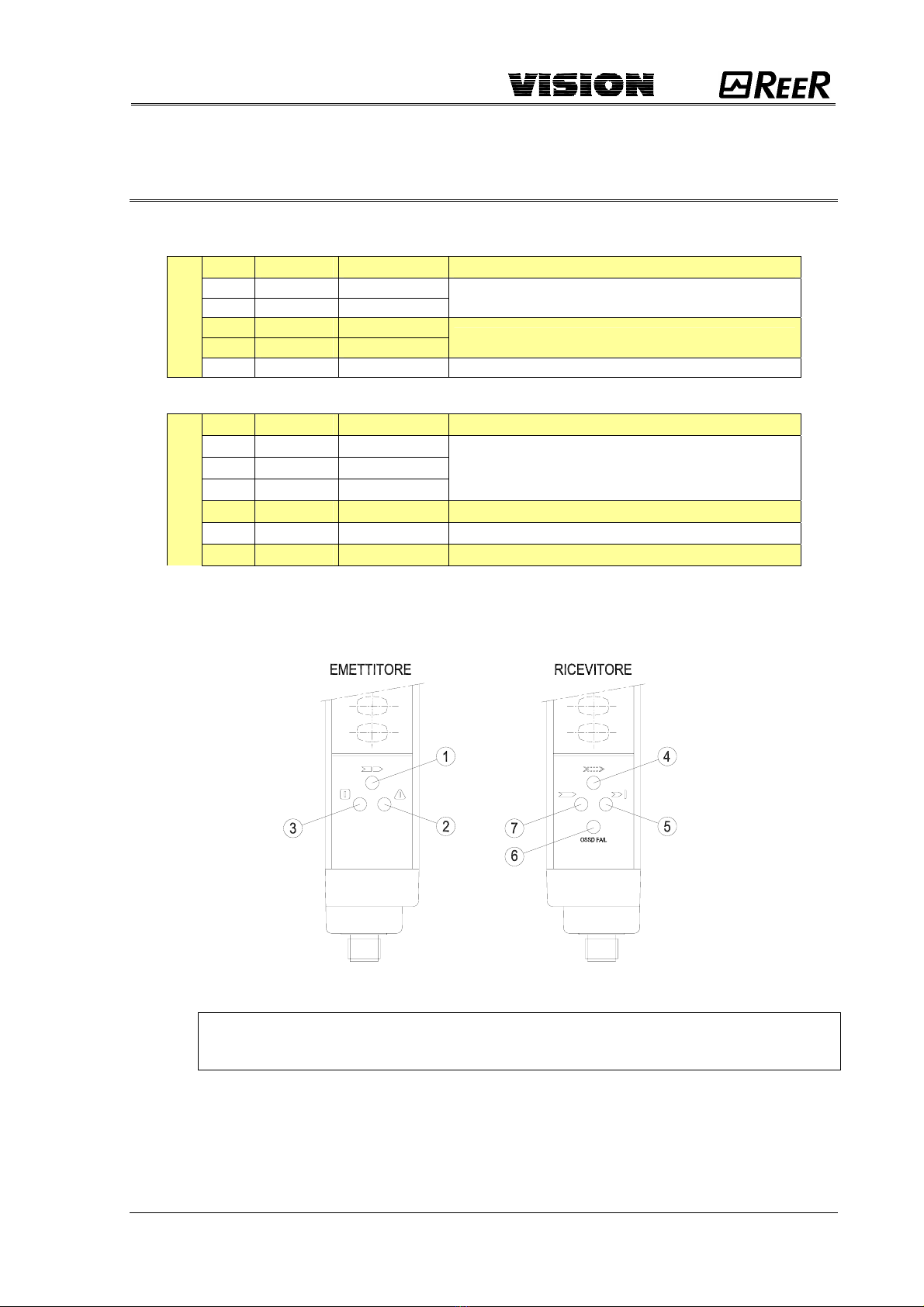
RICEVITORE
LED
Giallo (4) Rosso (5) Rosso (6) Verde (7) DIAGNOSI RISOLUZIONE
Lamp.
VELOCE
ogni 0,5s ON Lamp.
VELOCE
ogni 0,5s OFF Guasto relativo alle
schede a
microcontrollore
Inviare l’apparecchiatura in
riparazione presso i laboratori
REER
OFF ON
Lamp.
VELOCE
ogni 0,5s OFF
Guasto alle uscite
statiche OSSD,
oppure uscite statiche
OSSD erroneamente
collegate a 24VDC
Verificare attentamente il
collegamento dei morsetti 2 e 4
(OSSD) presenti sul connettore.
Se non si risolve:
Inviare l’apparecchiatura in
riparazione presso i laboratori
REER
Lamp.
VELOCE
ogni 0,5s ON OFF OFF
Guasto alle schede
ottiche
Inviare l’apparecchiatura in
riparazione presso i laboratori
REER
OFF ON
Lamp.
LENTO
ogni 1s OFF
Assorbimento di
corrente eccessivo
sulle uscite OSSD o
uscite in corto circuito
tra di loro
Verificare attentamente il
collegamento dei morsetti 2 e 4
(OSSD) presenti sul connettore.
Tali morsetti potrebbero essere
direttamente collegati a
+24Vdc, a 0Vdc o cortocircuitati.
Lamp.
LENTO
ogni 1s ON OFF OFF
Rilevata condizione
pericolosa di
Emettitore interferente.
Il Ricevitore è in grado
di ricevere
contemporaneamente
i raggi emessi da due
diversi Emettitori.
Ricercare attentamente
l’Emettitore disturbante ed
intervenire in uno dei seguenti
modi :
•Scambiare la posizione di
Emettitore e Ricevitore
•Spostare l’Emettitore
interferente per evitare che
illumini il Ricevitore
•Schermare i raggi provenienti
dall’Emettitore interferente
mediante protezioni opache
In ogni caso, a fronte di un blocco del sistema, si consiglia uno spegnimento ed una
riaccensione, in modo da verificare che la causa del comportamento anomalo non sia
imputabile ad eventuali disturbi elettromagnetici di carattere casuale.
Nel caso sussistano irregolarità di funzionamento, occorre:
•controllare l'integrità e la correttezza delle connessioni elettriche;
•verificare che i livelli di tensione di alimentazione siano conformi a quelli
indicati nei dati tecnici;
•Si consiglia di tenere separata l'alimentazione della barriera da quella di altre
apparecchiature elettriche di potenza (motori elettrici, inverter, variatori di
frequenza) o altre fonti di disturbo.
•controllare che l’Emettitore e il Ricevitore siano correttamente allineati e che le
superfici frontali siano perfettamente pulite.
In caso non sia possibile identificare chiaramente il malfunzionamento e porvi
rimedio, fermare la macchina e contattare il servizio di assistenza ReeR.