RAB STL360HB/L User manual

INSTRUCTIONS
STL360H/L, STL360HB/L INSTALLATION
RAB Lighting is committed to creating high-quality, affordable, well-designed and energy-efficient LED lighting and controls that make it easy for electricians to install
and end users to save energy. We’d love to hear your comments. Please call the Marketing Department at 888-RAB-1000 or email: mark[email protected]
1
HOW DO THE SCANNING LED DETECTION
INDICATORS WORK?
Scanning LEDs serve as a deterrent by indicating a security device
in operation. They also show the STL360’s mode of operation.
Automatic Mode
When the STL360 is “On Guard” in Auto mode, three red LEDs scan
continuously day and night, except during detections (at which time
the controlled lights will go on and LEDs will be off).
Test Mode
When the sensor is in “Test Mode” all of the LEDs will be off.
Manual Override Mode
When the sensor is ready for “Manual Override Mode” the middle
LED will be on steady.
Evening Timer Mode
When the sensor is ready for “Evening Timer Mode Mode” the
middle LED will be blink.
IMPORTANT
READ CAREFULLY BEFORE INSTALLING FIXTURE. RETAIN THESE INSTRUCTIONS FOR FUTURE REFERENCE.
RAB fixtures must be wired in accordance with the National Electrical Code and all applicable local codes. Proper grounding is
required for safety. THIS PRODUCT MUST BE INSTALLED IN ACCORDANCE WITH THE APPLICABLE INSTALLATION CODE BY A PERSON
FAMILIAR WITH THE CONSTRUCTION AND OPERATION OF THE PRODUCT AND THE HAZARDS INVOLVED.
WARNING: Make certain power is OFF before installing or maintaining fixture. No user serviceable parts inside.
CAUTION: TURN OFF ALL POWER AT CIRCUIT BREAKER/FUSE PANEL. The total lighting load connected to Stealth must
not exceed 8 amps 277V (LED load). To switch more wattage an electrician can install a relay. Line Carrier Remote Control
Systems such as X-10 or Leviton are incompatible with sensors and cause false activations.
DO NOT INSTALL SENSORS ON A CIRCUIT THAT FEEDS MOTOR LOADS LIKE KITCHEN APPLIANCES, HVAC EQUIPMENT,
WASHER/DRYER, OR GARAGE DOOR OPENERS. Sensor must be below and as far as possible away from lights. Sensor
functions best when the direction of expected movement is across its detection pattern, not towards the sensor. Mount
6–12 feet high for optimum range and detection.
STL360HB/L STL360H/L
“On Guard Auto Mode”
LEDs scan continuously back & forth
“Test Mode” all LEDs off
Middle LED on steady is Manual Override Mode
Middle LED blinking is Evening Timer Mode

INSTRUCTIONS
STL360H/L, STL360HB/L INSTALLATION
RAB Lighting is committed to creating high-quality, affordable, well-designed and energy-efficient LED lighting and controls that make it easy for electricians to install
and end users to save energy. We’d love to hear your comments. Please call the Marketing Department at 888-RAB-1000 or email: [email protected]
2
SETTINGS
How long do the lights stay on?
Lights remain on as long as there is movement within the
protection zone. Once the zone is vacated lights can be adjusted
to remain on approximately 5 seconds up to 12 minutes. Since the
lights are on only when needed, and the sensor uses only one watt.
The Stealth is extremely energy efficient.
Can outdoor lights still be turned on with the light switch?
Yes. STL360 can be controlled by a conventional indoor switch or
circuit breaker. STL360 operates in the auto mode unless changed.
Lights can be turned on or off manually at night only with the
Manual Override Mode.
Wall Switch Manual Override (to keep lights on)
Flip the switch twice slowly (off-on-off-on) within 1-2 seconds. If
you set this during the sensor will become “ready” for the Manual
Override Mode and will start Manual Override at dusk.
Evening Timer (to keep lights on, and is repeated every night)
Flip the switch three times slowly (off-on-off-on-off-on) within 1½ - 3
seconds. You can set this during the day and the Evening Timer
Mode will begin at dusk.
To Resume Automatic Mode
Switch power off for at least 10 seconds, then back on.
Will STL360 detect animals?
STL360 may detect large animals. Having animals trigger the sensor
can give property a “lived-in” look. However, you can limit animal
detection by turning down the sensitivity knob and/or placing the
blinders provided on the lower part of the forward lens.
How do you make adjustments to the sensor?
Use the adjustment tool provided, or a screwdriver with a 1/8" wide
blade. To adjust the controls on the front of the sensor see page 5.
CHOOSING A LOCATION
The best location is where the sensor can “see” all paths of
movement. The sensor may be wall or soffit mounted. As distance
from the sensor increases, larger movement will be required for
detection. For instance, at 10 feet, a half step will be enough, while
at 50 feet several steps will be necessary for detection.
How large an area does STL360 protect?
Two powerful detectors combine to give the STL360 180ºx 60' wide
with 60' forward range plus superb 360ºdownward detection
below and to all sides.
Mounting Height
Mounting at 6-10' above the ground allows maximum range. If the
sensor is mounted above 15' high, the usable range is reduced.
Difficult Locations
Sensor may be triggered by unwanted
movement or heat source, such as a swaying
tree, road traffic, dryer vent, swimming pool
or hot tub.
To improve performance in difficult locations:
• Reduce sensitivity by turning the SENS knob counterclockwise
and/or…
• Mask lens in the direction of the unwanted movement or heat
source using the lens mask provided or opaque tape.
TIME
1 8 HRS 5 SECS 12 MINS – +
EVENING
TIMER
SENS
TIME
1 8 HRS 5 SECS 12 MINS
– +
EVENING
TIMER
SENS
mask
side view
20'
120'
60'
6-10'
10'
60'
6-10'
40'
Reduced RangeMaximum Range
20'

INSTRUCTIONS
STL360H/L, STL360HB/L INSTALLATION
RAB Lighting is committed to creating high-quality, affordable, well-designed and energy-efficient LED lighting and controls that make it easy for electricians to install
and end users to save energy. We’d love to hear your comments. Please call the Marketing Department at 888-RAB-1000 or email: [email protected]
3
Mounting Stability
Mount sensor on stable surface. Do not mount
on a tree or pole that will move in the wind.
Light vs. Sensor Position
• Make sure sensor and lights are mounted
firmly. If they move when touched, tighten
all screws.
• Make sure heat from lights is not triggering
sensor. Sensor must be located below and as
far away as possible from its lights.
Locations Near Roads
Cars and passing traffic may activate the sensor if it is aimed at
the road.
To Improve Performance in Difficult Locations:
• Reduce sensitivity by turning the SENS knob counterclockwise,
• Mask lens in the direction of
the traffic using the lens mask
provided or opaque tape.
(Lens Mask can be broken along
lines to desired size)
• Make sure that sensor is not
aimed at traffic. The sensor
should be aimed down so that the maximum range of the
sensor ends at least 20’ from the road. This will avoid detection
of passing trucks and cars, or the air currents they create.
Mount Level
The sensor should be mounted level from side to side and pointed
at the area where you desire coverage. If tilted, part of the detection
zone may be high in the air over people’s heads.
Locate for Movement Across
Pattern
Check that movement is not directly
towards sensor. Sensor will see
movement ACROSS its pattern move
quickly. Check that movement far
away and directly towards sensor is
not entirely within one zone. To fix,
change the sensor angle or location.
Location Over a Pathway
If the sensor is located over a
pathway so all movement is directly
toward it, range may appear limited.
“Micro Adjust” sensor by moving
sideways 1/4" or so, which may
reposition the zones enough to allow
earlier detection.
Choose a Protected Location
Mount sensor in protected area. The more protected the mounting
location, the less chance of lights turning on occasionally during
rain, snow and windstorms. This could happen because the sensor
is detecting dramatic changes in temperature.
ASSEMBLY AND WIRING
STL360 floodlight kits come pre-wired and assembled on the
RAB CU4 EZ plate, allowing for mounting on round, rectangular or
octagonal surface or recessed boxes.
Mounting
TIME
1 8 HRS 5 SECS 12 MINS – +
EVENING
TIMER
SENS
Lens Mask
(included)
WRONG OK!
WRONG OK!
Insert
close-up
plug in
unused
hole
Finishing
Cap
Bar Screws
Gasket &
Surface Plate
Universal
Mounting
Bar
Hook
O-Ring
Gasket
CU4 EZ Plate
Gasket
Center
Screw
Fig: 1
OK!
20'
safety zone
CHOOSING A LOCATION (cont’d)
wrong
OK! wrong
More sensitive
Less
sensitive
Better detection after
“micro adjustment”

INSTRUCTIONS
STL360H/L, STL360HB/L INSTALLATION
RAB Lighting is committed to creating high-quality, affordable, well-designed and energy-efficient LED lighting and controls that make it easy for electricians to install
and end users to save energy. We’d love to hear your comments. Please call the Marketing Department at 888-RAB-1000 or email: [email protected]
4
Wiring
Red pigtail is only used to switch remote or additional fixtures.
1. Attach the Universal Mounting bar with the screws provided
to the junction box. If you are attaching your STL360 kit to a
surface mount weatherproof box, you must use with the metal
mounting plate with gasket.
2. Easy Wiring Tip: Use the “S” shaped
Hands Free Hanging Hook to hold
the CU4 EZ Plate during wiring.
3. Bring power leads and sensor
kit leads through holes in gasket
and plate into junction box.
4. Strip 1/2" of insulation from all leads.
5. Attach ground wire(s) to junction box
grounding screw. Connect as shown in
wiring diagram as shown in Fig. 2.
6. Twist on wire nuts. Secure with electrical tape.
7. Align CU4 EZ Plate and metal surface plate with gasket (for
use with surface mounted junction boxes) to ensure proper seal.
Tighten CU4 EZ Plate center screw (make sure O-Ring gasket is on
the screw) to attach CU4 EZ Plate to the box.
8. Insert plastic Finishing Cap in the center of the CU4 EZ Plate for a
weatherproof seal.
9. Use silicone sealant around plate and all opening to ensure a
weather proof seal. Seal all unused conduit entries on surface
junction box.
10.Screw in light bulbs. Turn on power. Conduct walk test to adjust
sensor response (see page 6).
■To install a STL360 Sensor with separately purchased
floodlights, start at #1.
■To install STL360 Pre-wired Floodlight Kits refer to Fig. 2.
1. Screw the threaded arms of each floodlight into the RAB CU4 EZ
Plate. (See Fig. 1.)
2. Screw the threaded arm of the sensor into the bottom hole of
the CU4 EZ Plate. Sensor should be below and as far away from
the floodlights as possible.
3. Attach the Universal Mounting bar with the screws provided to
the junction box. If you are attaching your STL360 kit to a surface
mount weatherproof box, you must use the metal mounting
plate with gasket.
4. Use the “S” shaped Hands Free Hanging Hook to hold the EZ
Plate during wiring.
5. Bring power leads and sensor kit leads through holes in gasket
into junction box.
6. Attach ground wire(s) to junction box grounding screw.
7. Position CU4 EZ Plate and metal surface plate with gasket
(required for mounting on surface junction boxes.) (See Fig. 1.)
8. Strip 1/2” of insulation from
all leads. Connect as shown
in wiring diagram.
9. Twist on wire nuts. Secure
with electrical tape.
10.Make sure all unused
openings in CU4 EZ Plate are closed with plugs (provided).
11. Use silicone sealant around plate and all openings to ensure a
weather proof seal. Seal all unused conduit entries on surface
junction box.
12. Screw in light bulbs. Turn on power.
13. Conduct walk test to adjust sensor response (see page 6).
Multiple Sensors
Multiple sensors may be wired together, but doing this will make
problems difficult to troubleshoot. Single sensors that control their
own lights will give a more accurate location of movement and
trouble-free operation.
Multiple Fixtures
Multiple fixtures may be wired to a single sensor. To handle loads
greater than 1000 watts, a qualified electrician should install a relay.
Black
Power In
White
Ground
Ground
White
Black
Red
Red Pigtail
Hood rests
in notch on
crossbar
Hands Free
Hanging
Hook
CU4 EZ Plate
Fig: 2
ASSEMBLY AND WIRING (cont’d)

INSTRUCTIONS
STL360H/L, STL360HB/L INSTALLATION
RAB Lighting is committed to creating high-quality, affordable, well-designed and energy-efficient LED lighting and controls that make it easy for electricians to install
and end users to save energy. We’d love to hear your comments. Please call the Marketing Department at 888-RAB-1000 or email: [email protected]
5
Power Quality
It is not recommended to install sensors on a circuit that also
feeds motor loads such as HVAC equipment, kitchen appliances,
or garage door openers. The Stealth circuit is surge and transient
protected to IEC specifications. However, if voltage varies
significantly from 120 volts, the sensor may malfunction. This may
occur on circuits with motor loads.
ADJUSTING THE SETTINGS
Time
Sets the time that lights will remain on after the detection zone
is vacated. Adjustable from approximately 5 seconds to 12 minutes.
The factory setting is 12 minutes.
Photocell
For night-only operation, turn the knob completely counter-
clockwise to (to the MOON symbol). For 24-hour operation turn
the knob all the way clockwise to the MOON/SUN symbol. Adjust
counterclockwise to have the sensor come on later at dusk,
clockwise to have it come on earlier. The Factory Setting is Night-
only (MOON). If you set Evening Timer while set to 24 hour operation
Evening Timer will begin immediately after flipping switch.
Sensitivity
Increases or decreases the responsiveness and range of the sensor
(adjustable from 30% to 100%). The Factory Setting is 100%.
Evening Timer
The STL360 provides an alternative to normal motion-activated
lighting. The EVENING TIMER can keep lights on continuously
– without motion – for 1 to 8 hours after dusk. This is great for
evening activities requiring continuous light. During vacations the
EVENING TIMER provides a “lived-in” look by simulating an occupant
turning lights on at dusk, and then off at bedtime.
To activate the EVENING TIMER, flip the wall switch controlling the
sensor three times slowly (off-on-off-on-off-on) within 3 seconds. If
you activate the EVENING TIMER during daytime, the middle LED
should start blinking, indicating that the EVENING TIMER will start
when dusk is detected.
Choose the length of time you want continuous lighting. For
example, if you set the EVENING TIMER to “8”, the sensor will keep
lights ON continuously for 8 hours after dusk. Once 8 hours have
passed, the sensor will revert to motion activated mode. At dawn,
the photocell will detect light and prevent lights from turning on
during the daytime. The Evening Timer Mode
will continue until you de-activate it.
If you do not want to use the EVENING TIMER,
do NOT flip the switch 3 times, as described
above.
To de-activate the EVENING TIMER, switch the
sensor OFF for at least 10 seconds, then ON
again. Sensor will be in Automatic Mode (after
completing the 30 sec warm-up period).
You can affix this label (right), provided, to your
indoor light switch plate for easy reference.
SENSOR MODES
Automatic Mode
Lights will turn on when there is movement within the detection
zone after dusk.
Evening Timer Mode
Keeps lights on for 1- 8 hours after dusk. Sensor then reverts to
Automatic Mode until dawn. If you set the Evening Timer Mode
during daylight, the sensor will be prepared to turn on at dusk and
remain on for the number of hours you set. When the sensor is in
“Ready for Evening Timer Mode”, the middle LED will blink 3 times,
pause and repeat. Set the Evening Timer by flipping the switch that
operates the sensor 3 times within 3 seconds (off-on-off-on-off-on).
TIME
1 8 HRS 5 SECS 12 MINS – +
EVENING
TIMER
SENS
TIME
1 8 HRS 5 SECS 12 MINS – +
EVENING
TIMER
SENS
TIME
1 8 HRS 5 SECS 12 MINS – +
EVENING
TIMER
SENS
TIME
1 8 HRS 5 SECS 12 MINS – +
EVENING
TIMER
SENS
“On Guard Auto Mode”
LEDs scan continuously back and forth
“Ready for Evening Timer Mode”
Middle LED blinks

INSTRUCTIONS
STL360H/L, STL360HB/L INSTALLATION
RAB Lighting is committed to creating high-quality, affordable, well-designed and energy-efficient LED lighting and controls that make it easy for electricians to install
and end users to save energy. We’d love to hear your comments. Please call the Marketing Department at 888-RAB-1000 or email: [email protected]
6
Test Mode
The Test Mode will allow you to test the sensor during the day
regardless of the photocell setting. To enter Test Mode, turn time
setting to 5 sec on the unit. Turn power off for 10 secs then back on.
There is a 30 second warm-up period, then the Test Mode starts.
During the warm-up, the lights stay on continuously and LEDs are
off. During Test Mode the LEDs remain off. The sensor will stay in
Test Mode until the detection zone is vacated for one minute.
During the Test Period, the sensor will keep lights on for 5 seconds
each time it detects movement in its detection zone. Perform the
walk test and make any adjustments needed. Vacate the detection
zone for one minute or more to end Test Mode. Scanning LEDs will
appear when test mode ends. Set back to desired time setting after
testing complete.
Manual Override Mode
The STL360 has a “protected” Manual Override that requires a
double-flip of the light switch so momentary power problems do
not interfere with normal sensor operation.
By flipping the switch that operates the sensor twice (off-on-off-on)
within 2 seconds you will override the sensor to keep lights on
continuously until dawn.
If you set the Manual Override Mode during daylight, the sensor will
be prepared to turn on at dusk and remain on until dawn. This is a
handy feature if you leave home for the day and you want the lights
on to greet you when you return. When the sensor is in “ Ready for
Manual Override Mode” the middle LED will be on.
To Resume Automatic Mode
Switch OFF the power for at least 10 seconds, then turn it ON
again. Sensor will reset to Automatic Mode after completing the
warm-up period.
Daytime (24-HOUR) Operation of Manual Override
If you set Manual Override while set to 24 hour operation, lights
will come on and remain on continuously. Lights will not turn off
at dawn.
WALK TESTING
STL360’s full coverage pattern reduces the need for aiming and
adjustment. The purpose of the Walk Test is to check and adjust the
coverage pattern. The STL360 must be manually set into Test Mode
(explained at left).
To enter Test Mode
Turn Time setting to 5 seconds and turn off sensor for 10 seconds.
After a warm up period of 30 seconds the LEDs will be off.
1. Aim the sensor at the traffic pattern you want to detect. Sensor
will detect any movement ACROSS its pattern most effectively.
2. Start outside the pattern and walk across the pattern until the
lights go on. As distance from the sensor increases, it will take
more movement to be detected.
3. Adjust sensor aiming as necessary to improve coverage. Make
sure sensor is level.
4. Sensitivity may be decreased with the SENS knob to detect a
limited area or if the sensor is being activated by wind, foliage,
traffic or animals, or increased to cover a larger area. (See page 6
to adjust sensor settings.) The lens mask can also be used to
drastically reduce coverage, or allow undetected movement
from some directions.
5. STL360 is factory set for night only operation. For 24 hour
operation, turn the photocell control completely toward the
SUN/MOON setting. Turn counter clockwise to have the sensor
come on later at dusk, clockwise to have it come on earlier.
6. Repeat steps 1-5 until you are satisfied with coverage. Vacate the
detection zone for 1 minute and then turn the settings back to
desired time delay. Your sensor is now ready for operation.
TECHNICAL TIPS
Lights Do Not Turn Off
1. Make sure that the sensor is not in Manual Override Mode. Turn
sensor OFF for 10 seconds, then back ON. The Sensor will be
go through 30 second warm up period where the lights are on
then will go into Automatic Mode with lights off and ready to
detect movement.
TIME
1 8 HRS 5 SECS 12 MINS – +
EVENING
TIMER
SENS
“Ready for Manual Override Mode”
Middle LED on
SENSOR MODES (cont ’d)

INSTRUCTIONS
STL360H/L, STL360HB/L INSTALLATION
RAB Lighting is committed to creating high-quality, affordable, well-designed and energy-efficient LED lighting and controls that make it easy for electricians to install
and end users to save energy. We’d love to hear your comments. Please call the Marketing Department at 888-RAB-1000 or email: [email protected]
7
2. Make sure that the sensor is not in Evening Timer Mode. Turn
power OFF for 10 seconds. (Refer to Step #1).
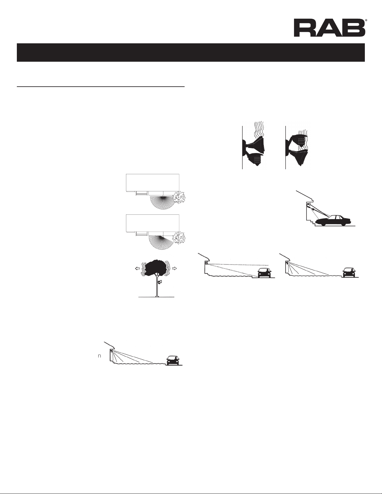
3. Make sure sensor is not aimed at or mounted over something
that would move or change temperature such as waving
branches, water, air conditioners, windows or heating vents even
on neighboring property. You can test for infrared sources in
the area by placing a box or bag over the sensor. Put sensor into
test mode. Lights should stay off. Wave your hand inside bag in
front of sensor. Lights should go on and then time out. If sensor
operates properly when covered, check items #4-8.
Problem:
Sensor is triggered by unwanted
movement or heat source.
Solution:
1. Aim sensor away from movement, or
2. Mask lens in the direction of the source
3. Lower sensitivity control setting
4. Make sure sensor and lights are
mounted firmly and do not move even
slightly when touched. If they move,
tighten all screws.
5. Make sure sensor is not mounted on an
unstable object such as a tree or pole that
will move in the wind.
Problem: Movement of tree triggers sensor.
Solution: Mount on stable surface.
6. Was sensor wired hot (with power on etc)? If so, circuitry may have
been damaged.
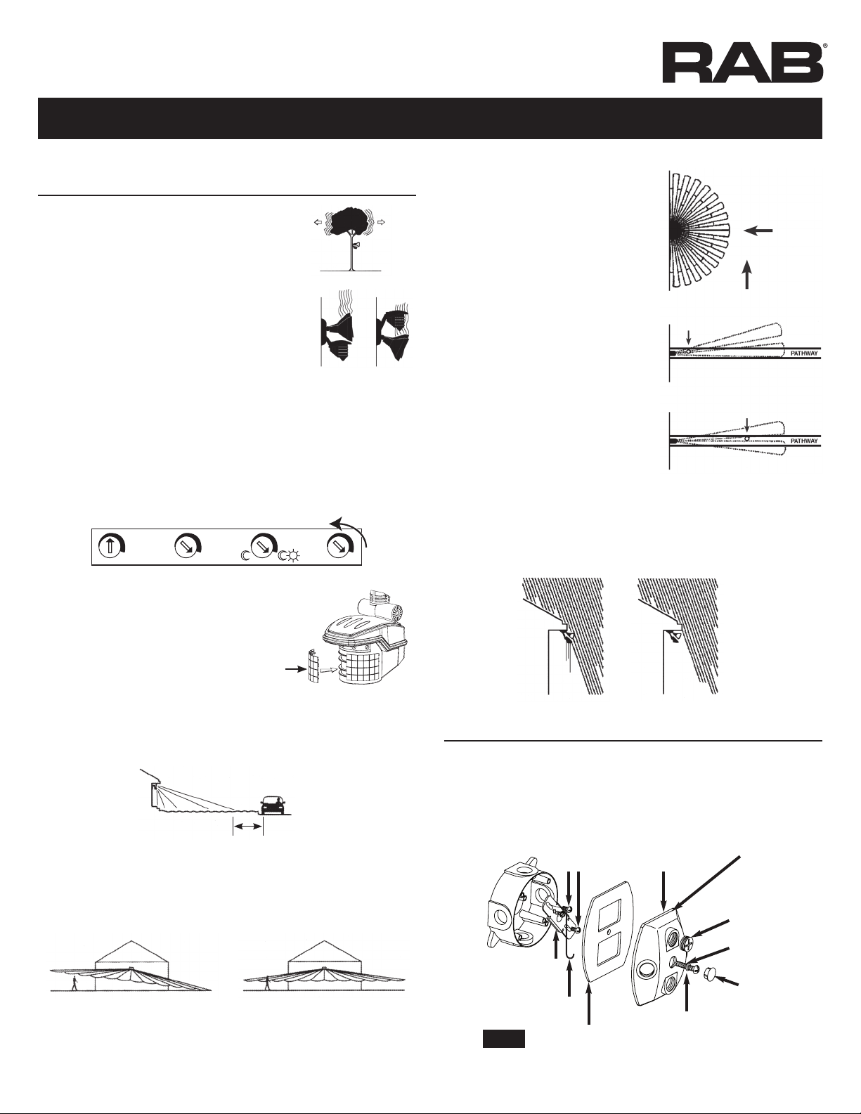
7. Make sure sensor is not aimed within 20 feet of a road.
Problem: Passing cars activate sensor.
Solution: A 20 foot safety
zone and lower sensitivity are
recommended to avoid activation
from passing cars.
8. Make sure heat from lights is not triggering sensor. Make sure the
sensor is below and as far as possible away from lights.
Lights Turn On and Off Inappropriately
1. Make sure the sensor is installed on its own dedicated circuit,
free of motor loads such as HVAC equipment, kitchen appliances
or garage door openers.
2. It is not recommended to wire sensors in parallel. More than
one sensor wired together makes them difficult to troubleshoot.
Disconnect multiple sensors and test separately.
3. Keep all people completely out of the detection pattern to make
sure the sensor is not detecting them.
4. Make sure sensor is located below and as far as possible from its
lights. Heat from the lights may trigger the sensor.
Solution: Move sensor below and away from the lights.
5. Make sure lights are not reflecting back into sensor. Check
for white or reflective surfaces
close to the sensor.
Solution: Aim sensor away from
reflective objects, or move the objects
and lower sensitivity.
6. Make sure sensor is not aimed within 20 feet of a road or
sidewalk. Passing cars will activate sensor.
Solution: A 20 foot safety zone and reduced sensitivity are
recommended to avoid activation from passing cars.
7. Heavy rain, snow or high winds may activate the sensor
occasionally. Reduce sensitivity control slightly until problem
stops.
8. Moths can be attracted to the lights and fly close to the sensor
causing triggering. Reducing the sensitivity may help.
9. Check Solutions #3, 4, 5, 6, 7 and 8 under “Lights Do Not Turn
Off”, beginning on page 6.
Lights Do Not Turn On
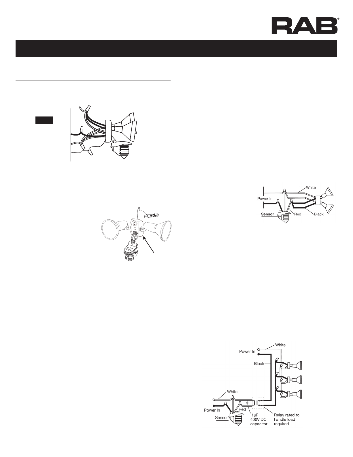
1. Check that lamps and fixtures work. Compare wiring to the
wiring diagram in this manual. Check that the power is on.
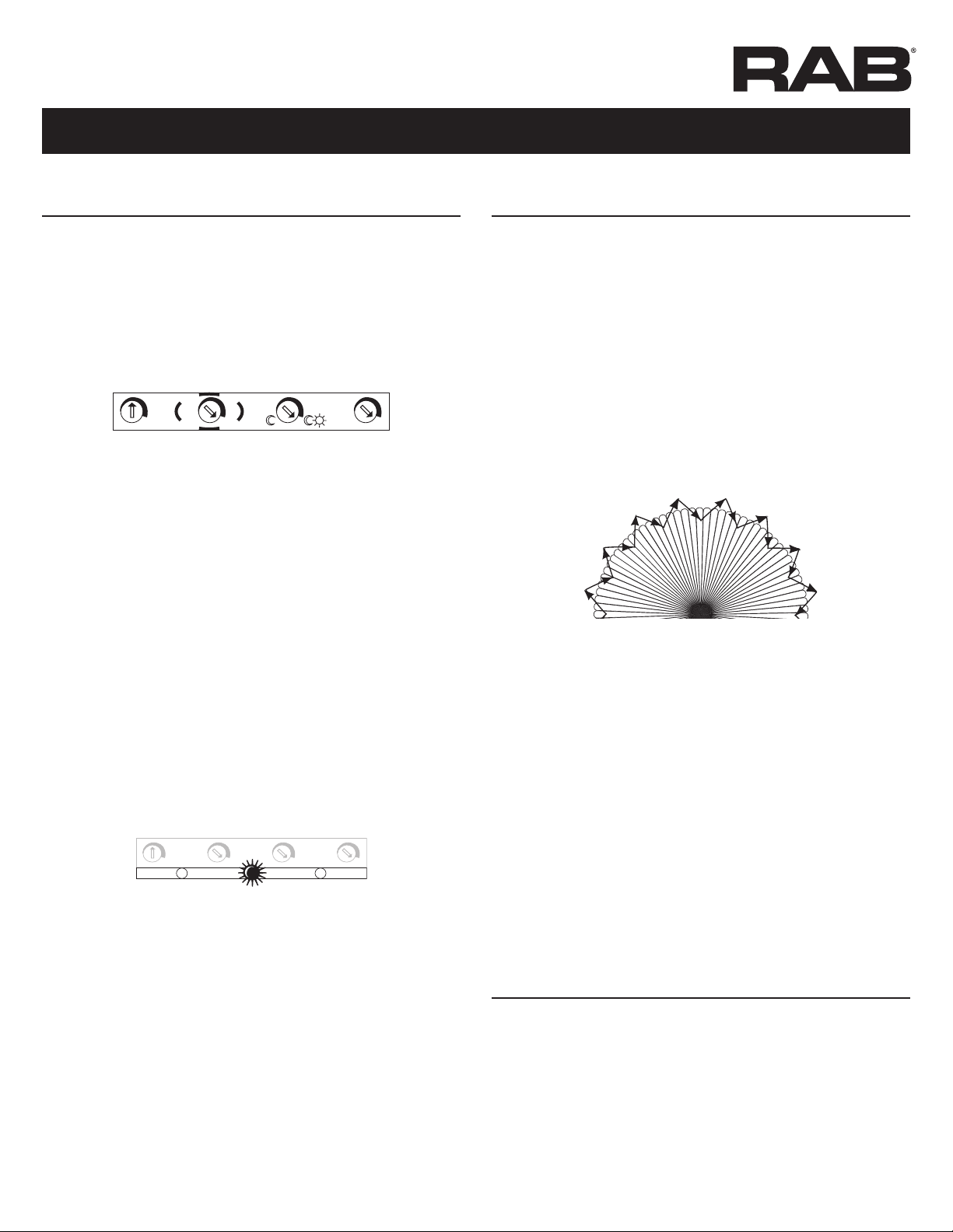
2. If installing during daylight, LED will go into automatic
mode after 30 sec warm up period and will not work during
daylight if the photocell is turned to the night only position
(moon symbol).
If you require a test mode, turn time setting to 5 seconds and
turn the power off at least 10 seconds and back on again.
WRONGOK!
TECHNICAL TIPS (cont ’d)

INSTRUCTIONS
STL360H/L, STL360HB/L INSTALLATION
RAB Lighting is committed to creating high-quality, affordable, well-designed and energy-efficient LED lighting and controls that make it easy for electricians to install
and end users to save energy. We’d love to hear your comments. Please call the Marketing Department at 888-RAB-1000 or email: [email protected]
8
If you require the sensor to
operate both day and night,
turn the SUN/MOON control
knob clockwise to the sun and
moon symbol.
3. Check that lights from another source, such as adjacent porch
lights, garden lights or street lights are not in the sensor’s
view. The sensor’s photocell may detect the light and
deactivate “daylight”.
If you desire the sensor to
operate in higher ambient
light levels, turn the SUN/
MOON control knob counter clockwise toward the sun symbol.
4. Was sensor wired hot? If so circuitry may have been damaged.
Lights Turn Off Too Quickly
1. Check if sensor is being “tricked” by reflected light. If lights
controlled by the sensor shine or reflect into the photocell
(located behind the lens) the
unit will go on briefly, see
its own light, and turn off
“thinking” that it is daytime:
Problems:
Lights reflect into photocell
Lights shine directly into
photocell
Solution: Adjust SUN/MOON
knob slightly clockwise, to allow
operation at higher ambient light
levels. Alternatively, move the
lights or reflectors or mask the lens in the direction of the lights
and/or reflections.
2. Check if “R” lamps, non-reflector “A” lamps or self-ballasted PL
lamps are being used in non-enclosed lampholder. If so, switch
to reflector PAR floodlight lamps so the sensor is not affected by
stray light. If using PAR floodlights, consider using lower wattage,
energy saving lamps.
Range Appears Limited
1. Check that the sensor is level from side to side and pointed at
the area you desire. If unit is tilted, part of the detection zone
may be high in the air over people’s heads.
Solution: Position sensor exactly level from side to side.
2. Check that the sensor is not mounted too high. If mounted
above 20', much of the usable range will be lost.
Solution: Mounting at 6’ to 10’
allows maximum range.
3. Check that movement is not
directly towards sensor. Sensor
will see movement across its
pattern more quickly. To fix,
move the sensor.
4. Check that movement far away and directly towards sensor is
not entirely within one zone.
Problem: Sensor will not detect until movement crosses zones.
Solution: ”Micro Adjust” sensor by moving sideways 1/4”. This may
move the zones to allow earlier detection.
TIME
1 8 HRS 5 SECS 12 MINS – +
EVENING
TIMER
SENS
Reduced Range
Maximum Range
60'
6-10'
40'
20'
WRONG OK!
More sensitive
Less
sensitive
TECHNICAL TIPS (cont ’d)
TIME
1 8 HRS 5 SECS 12 MINS – +
EVENING
TIMER
SENS
TIME
1 8 HRS 5 SECS 12 MINS – +
EVENING
TIMER
SENS
No detection until here
Detection here now

INSTRUCTIONS
STL360H/L, STL360HB/L INSTALLATION
RAB Lighting is committed to creating high-quality, affordable, well-designed and energy-efficient LED lighting and controls that make it easy for electricians to install
and end users to save energy. We’d love to hear your comments. Please call the Marketing Department at 888-RAB-1000 or email: [email protected]
9
P-100276
Easy Answers
rablighting.com
Visit our website for product info
Tech Help Line
Call our experts: 888 722-1000
e-mail
Free Lighting Layouts
Answered online or by request
© 2022 RAB LIGHTING Inc.
Northvale, New Jersey 07647 USA
RAB WARRANTY: RAB’s warranty is subject to all terms and conditions found at rablighting.com/warranty PATENT: Patent information can be found at rablighting.com/ip
CONTENTS OF ACCESSORY KIT
• 2 Lens Masks
• Indoor Switchplate Label
• 3 Wire Nuts
• Adjustment Tool
• Mylar lens Mask
• Crossbar with Green Ground Screw
• Hanging Hook
• 1/2" Close Up Plugs (3)
• Slotted Screws (4)
• Finishing Cap
• O-ring Gasket
• Center Mounting Screw
• Metal Surface Mounting Plate with Gasket
This manual suits for next models
2
Table of contents
Other RAB Lighting Equipment manuals

RAB
RAB GT500R/L User manual

RAB
RAB STEALTH 360 User manual

RAB
RAB STL200H/L User manual

RAB
RAB DRI-21-EMGR-DC-D10 User manual

RAB
RAB EZPAN HE 1X4 User manual

RAB
RAB PLL-14-8 DIR Series User manual

RAB
RAB STL110H/L User manual

RAB
RAB ECOMBO34 User manual

RAB
RAB FFLEDXS User manual

RAB
RAB X17 XFU 60W User manual
Popular Lighting Equipment manuals by other brands

Chauvet Professional
Chauvet Professional onAirPanel1IP user manual

Autopilot
Autopilot Pool Pilot Digital Nano Owners and installation manual

LumenRadio
LumenRadio W-DALI Instructions for use

Uplus Lighting
Uplus Lighting IP MATRIX 5 user manual

Insignia
Insignia NS-LED16RGB18 Quick setup guide

Eterna
Eterna EMLED3M installation instructions