Reese 3400 User manual

Reese 3400 Drum Mower
Operators Manual
New Zealand
REESE ENGINEERING LTD,
PALMERSTON NORTH,
NEW ZEALAND
Tel: 06 357 9323
Fax: 06 354 3155
e-mail: reese@xtra.co.nz
WEBSITE: www.reese.co.nz
Australia
REESE ENGINEERING LTD,
GEELONG, VICTORIA,
AUSTRALIA.
Freephone: 1-800-140-196
Freefax: 1-800-140-195
e-mail: ree[email protected]
WEBSITE: www.reese.co.nz
FOR YOUR NEAREST
DEALER AND FURTHER
INFORMATION CONTACT
USA
REESE AGRI-USA,
BRAYMER, MISSOURI,
USA
Tollfree: 800-717-3373
Fax: (660) 645 2214
e-mail: ree[email protected]
WEBSITE: www.reese.co.nz

Reese UFO 3400 Operators Manual
- 1 -
Dear Valued Owner,
Congratulations and thank you. You have just made an excellent investment.
Your new Reese Mower has been designed and engineered to give years of dependable service.
Every consideration has been taken to incorporate the latest technology, thus ensuring optimum
performance is achieved, whilst retaining our company desire to produce user friendly, low
maintenance solutions.
It has often been said “when all else fails-read the operators manual” and to ensure you get the
best from your new Reese Mower it is very important that you thoroughly read through the entire
contents of the manual. Please also pay attention to the maintenance recommendations,
understand the hydraulic system and consider the design features and their specific functionality.
If your new mower is maintained to a high standard and used as per this operator’s manual you
should be rewarded with many years of quality service.
Your local dealer carries an extensive range of genuine Reese spare parts and consumables that
also have been engineered to provide long service and life. It is important that only genuine parts
are used on your mower. We give you our commitment that we will support this machine with
spare parts backup for well beyond its designed life.
Thank you for making your investment in our expertise.
Yours Sincerely,
Ross Simpson
Director
Reese Agri

Reese UFO 3400 Operators Manual
- 2 -
Table of Contents
A. SAFETY SECTION............................................................................................................- 4 -
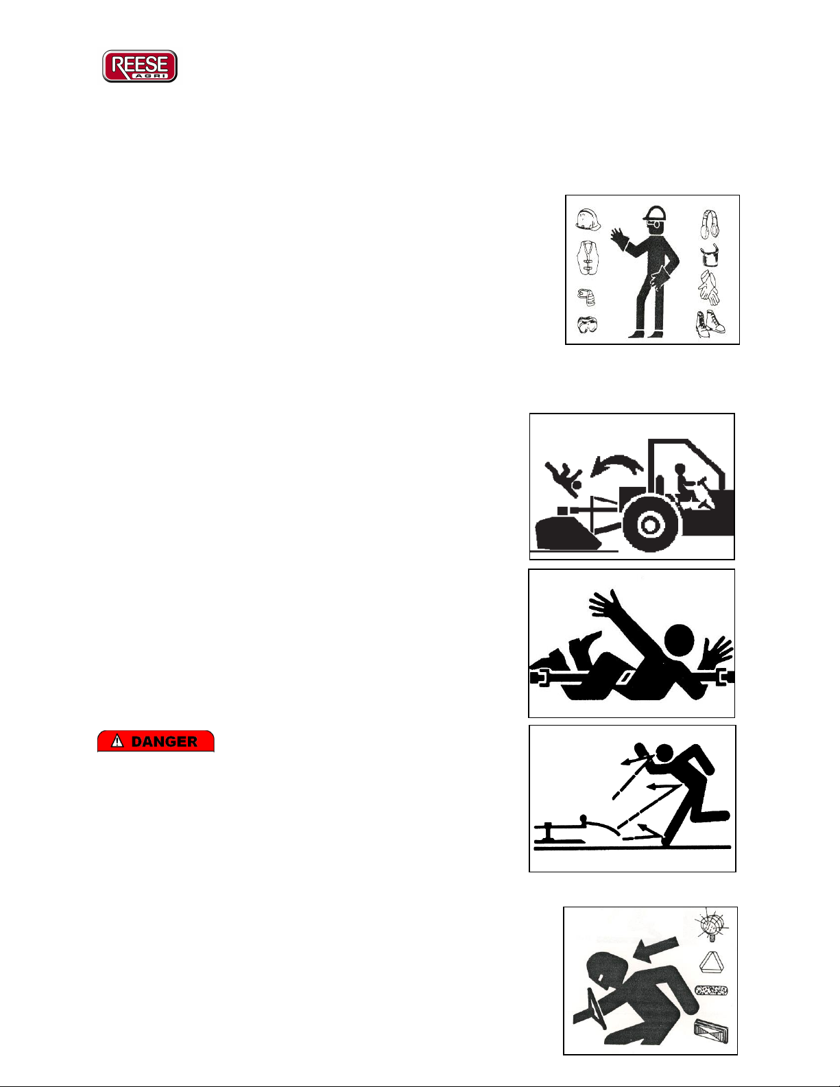
A.1. General Safety Instructions.........................................................................................- 4 -
A.2. Operator Safety Instructions........................................................................................- 5 -
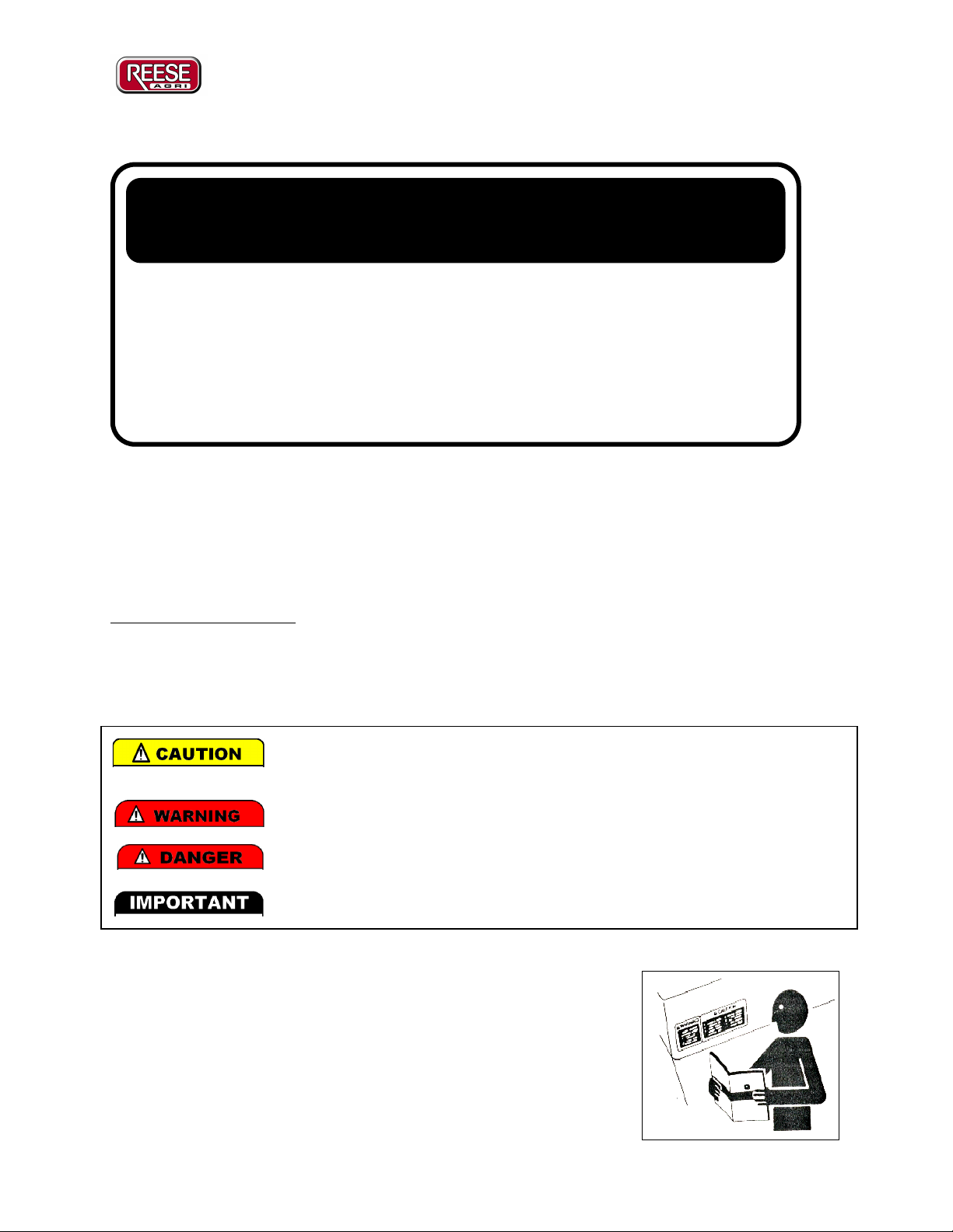
A.3. Decal Locations and Descriptions...............................................................................- 7 -
Decal List ............................................................................................................................- 7 -
Decal Locations...................................................................................................................- 8 -
Decal Descriptions ..............................................................................................................- 8 -
B. INTRODUCTION SECTION..............................................................................................- 12 -
B.1. To the Operator/Owner .............................................................................................- 12 -
B.2. The REESE 3400 Drum Mower................................................................................- 12 -
Technical Specifications ...................................................................................................- 13 -
B.3. Warranty....................................................................................................................- 13 -
Warranty Procedures.........................................................................................................- 13 -
Warranty Agreement.........................................................................................................- 13 -
B.4. Parts Ordering and Maintenance Procedures ............................................................- 14 -
C. ASSEMBLY AND SETTING UP SECTION......................................................................- 15 -
C.1. Delivery Checklist.....................................................................................................- 15 -
C.2. Assembly from Crate ................................................................................................- 15 -
Parts List............................................................................................................................- 15 -
Assembly Instructions.......................................................................................................- 16 -
C.3. Assembly from Pallet................................................................................................- 19 -
C.4. Setting up...................................................................................................................- 20 -
1) Tensioning the Belts..................................................................................................- 20 -
2) Setting the Torsion Bar .............................................................................................- 21 -
3) Cutting the PTO Shaft to Length...............................................................................- 22 -
4) Setting the Drawbar Extension Height and Drawbar Angle .....................................- 23 -
5) Setting the Drawbar Ram..........................................................................................- 24 -
6) Ensuring the Hydraulics are Set and Operating Correctly........................................- 24 -
7) Greasing and Lubrication Prior to Initial Use...........................................................- 26 -
C.5. Pre Operation Checklist ............................................................................................- 27 -
C.6. Safety Inspections .....................................................................................................- 27 -
D. OPERATION SECTION .....................................................................................................- 28 -
D.1. Servicing....................................................................................................................- 28 -
1) Prior to Initial Use.....................................................................................................- 28 -
2) Daily or after each 40 hectares (100 acres) of cutting...............................................- 28 -
3) Weekly or after each 200 hectares (500 acres) of cutting.........................................- 28 -
4) Annually before each Season....................................................................................- 28 -
5) Diagram of Grease Points .........................................................................................- 29 -
D.2. Operation...................................................................................................................- 30 -
D.3. Mowing Hints............................................................................................................- 31 -
1) Ragged Windrow.......................................................................................................- 31 -
2) Rough Stubble...........................................................................................................- 31 -
3) Cut Uneven –Scalloped............................................................................................- 31 -

Reese UFO 3400 Operators Manual
- 3 -
4) Uncut Stalks (Stripping)............................................................................................- 31 -
5) Mower slewing across behind tractor........................................................................- 31 -
6) Crop wrapping around drums....................................................................................- 31 -
D.4. Transporting..............................................................................................................- 32 -
E. MAINTENANCE SECTION...............................................................................................- 33 -
E.1. Storage Recommendations........................................................................................- 33 -
E.2. Fitting a Set of “V” Belts ..........................................................................................- 33 -
E.3. Belt Tension Adjustment...........................................................................................- 34 -
E.4. Replacement of Drum Bearing..................................................................................- 34 -
E.5. Replacement of Cutting Blades.................................................................................- 35 -
E.6. Drum Repairs ............................................................................................................- 35 -
E.7. Gearbox Oil...............................................................................................................- 35 -
F. PARTS SECTION ................................................................................................................- 36 -
F.1. Parts List 1: Mower Parts.........................................................................................- 36 -
F.2. Parts List 2: Drawbar Parts.......................................................................................- 38 -
F.3. Parts List 3: Pulley’s and Rotors Parts .....................................................................- 39 -
F.4. Parts List 4: Hydraulic Circuit Parts ........................................................................- 40 -

Reese UFO 3400 Operators Manual
- 4 -
A.SAFETY SECTION
A.1. General Safety Instructions
All implements with moving parts are potentially hazardous. All operators of such machinery
should operate in a cautious, safe, and responsible manner. The manufacturer has sought to
design this implement with safety as a primary objective. All safety guarding should remain on
the implement during operation and all warnings should be adhered to at all times.
BEFORE OPERATING you must read and understand the manual carefully to ensure a safe
working environment.
You will notice that both the manual and the mower contain decals and messages labeled either
‘CAUTION’, ‘WARNING’, ‘DANGER’, or ‘IMPORTANT’:
Follow Safety Instructions:
Carefully read all safety messages in this manual and on your
machine safety signs. Replace missing or damaged safety signs,
these can be ordered from your local Reese dealer.
Learn how to operate the machine and how to use controls properly.
Do not let anyone operate it without instruction. Keep your machine
in proper working condition. Unauthorized modifications to the
! WARNING !
The operation and adjustment of the Reese Machine requires a
complete knowledge of the contents of this handbook. To avoid
personal injury please ensure that all personnel are thoroughly
conversant with all details before commencement of operation
or maintenance.
The lowest level of safety message. Warns of possible injury. Decals
located on the equipment with this signal word are Black and Yellow.
Serious injury or possible death! Decals are Red/Yellow and Black.
Imminent death/critical injury. Decals are Red and White.
Important information regarding setup or operation.

Reese UFO 3400 Operators Manual
- 5 -
machine may impair the function and/or safety and affect machine life.
If you do not understand any part of this manual and need assistance, contact your Reese dealer.
Wear Protective Clothing
Wear close fitting clothes and safety equipment appropriate to the
job. Wear suitable hearing protective device as prolonged exposure
to loud noise can cause impairment or loss of hearing. Wear safety
gloves when working with blades as they can have sharp edges.
Operating equipment safely requires the full attention of the
operator. Do not wear radio headphones while operating machine.
A.2. Operator Safety Instructions
No riders or Children Operators
Allow no children on or near the folding mower or tractor.
Allow no riders on tractor or implement. Falling off may cause
serious injury or death from being run over by tractor or mower
or contact with rotating blades. They are subject to injury such
as being struck by foreign object and being thrown off the
machine. They also obstruct the operators view.
Moving Parts and Flying Object Dangers
Do not leave tractor with the mower still operating. There are
many moving parts including the PTO shaft, gearbox, belts,
pulleys, and blades that could cause serious injury or death.
Ensure the rotors have come to a complete stop before
approaching the machine and/or making any adjustments.
Ensure during operation all safety guards are
fitted to minimize the risk of flying objects. Beware of
passerby’s when operating so that no injury or death will occur
from a flying object.
Transport Safety
Slow moving tractors and equipment can create a hazard when
driven on public roads. They are difficult to see, especially at night.
This could lead to personal injury or death if a collision with a
vehicle occurs.

Reese UFO 3400 Operators Manual
- 6 -
Whenever driving on public roads, use flashing warning lights. Provide extra lighting at night on
machine and tractor. An implement safety lighting kit is available from Reese Engineering.
Always display SMV decal during transport. Follow local traffic codes.
The Reese 3400 Mower should not be towed at speeds greater then 30 km/h.
Never transport at any speed which does not permit adequate control of steering and stopping.
When transporting ensure the transport pin is correctly located and the side flaps are lifted and
secured. See section D.4 for more details on transporting. Ensure the PTO is not engaged and is
safely secured as per the PTO manufacturer’s operation manual.
Practice Safe Maintenance
Understand service procedure before doing work. Keep area clean and dry.
Never lubricate, service, or adjust machine while it is moving. Keep hands, feet and clothing
from power driven parts. Disengage all power and operate controls to relieve pressure. Lower
equipment to the ground. Allow machine to cool.
Securely support any machine elements that must be raised for
service work. Block up or support raised machine and all lifted
components securely before putting hands or feet under or working
underneath any lifted component to prevent rushing injury or death
from sudden dropping or inadvertent operation of controls. Make
certain area is clear before lowering or folding.
Keep all parts in good condition and properly installed. Fix damage
immediately. Replace worn or broken parts. Remove any buildup of
grease, oil, or debris.
Remove paint before welding or heating. Avoid potentially toxic
fumes and dust when sanding, repainting or welding. Do all work
outside or in a well-ventilated area. Dispose of paint and solvent
properly.
Avoid heating near pressurized fluid lines or other flammable
materials. Pressurized lines can be accidentally cut when heat goes
beyond the immediate flame, which could result in severe burns to
yourself and bystanders.
Avoid high-pressure fluids. Escaping fluid under pressure can cause
injury. Relieve pressure before disconnecting hydraulic or other
lines.
Dispose of Waste Properly

Reese UFO 3400 Operators Manual
- 7 -
Improper disposing of waste can threaten the environment and ecology. Use leak-proof
equipment when draining fluids. Do not use food or beverage containers that may mislead
someone into drinking from them.
Do not pour waste onto the ground, down a drain, or into any water source. Use the
manufacturer’s directions on the correct way to recycle or dispose of waste and be aware of
local law regarding waste disposal.
A.3. Decal Locations and Descriptions
Decals have been included to provide both information and warning signs for the operator and
other personal near the machine. It is important that if any of these decals are damaged or
removed that they must be replaced by the operator before the machines is used.
Decal List
See the table below for a complete list of the decals used on the 3400 Mower. This is
accompanied with a diagram showing the placement of the mower and then a complete
description of each decal.
Item
Part #
Qty
Type
Description
1
D1050
2
Logo
Reese/UFO
2
D1074
2
Logo
3400
3
D1075
1
Information
Belt Drive Layout
4
D1076
2
Danger
Thrown Object Hazard
5
D1260
1
Important
Drawbar Stand Positions
6
D1261
1
Warning
PTO Entanglement
7
D1262
1
Warning
Rotating Parts
8
D1263
3
Caution
Pinch Point
9
D1265
2
Important
Belt Covers
10
D1268
1
Reflect
Slow Moving Vehicle (SMV)
11
D1269
1
Important
Power/Weight 3400
12
D1272
1
Important
Transport Pin Placement
13
D1300
3
Danger
Rotating Parts
14
D1401
2
Warning
Rotating Blade
15
D1402
1
Warning
Farm Tractors
16
D1503
1
Important
Check PTO
17
D1008
1
Caution
Avoid Injury
18
D1518
21
Information
Grease Point

Reese UFO 3400 Operators Manual
- 8 -
Decal Locations
Decal Descriptions
1. D1050 –Logo –Reese/UFO
Company and Brand name of the mower.
2. D1074 –Logo –3400
Indicates the model number of the machine and
also the cutting width at 3.4m.
3. D1075 –Information –Belt Drive Layout
Shows the layout of each of the four drive belts.
Helpful for belt replacement and adjusting. See
Section E.2 for more details.

Reese UFO 3400 Operators Manual
- 9 -
4. D1076 –Danger –Thrown Object Hazard
To prevent serious injury or death from thrown
objects follow the given instructions; do not
operate with deflectors removed, do not point
discharge towards people, animals, or building
when operating, use special care when
operating in populated or congested areas.
5. D1260 –Important –Drawbar Stand
Positions
The drawbar stand can be locked in two
positions. Lock it at right angles to the drawbar
when machine is parked. Always lock it
horizontally with the drawbar when the machine
is connected to tractor.
6. D1261 –Warning –PTO Entanglement
Rotating Parts Warning –always operate with
guards in place. Never remove guards while
PTO is engaged.
7. D1262 –Warning –Rotating Parts
Rotating Parts Warning –Always operate with
guards in place never remove guards while
PTO is engaged.
8. D1263 –Caution –Pinch Points
Be aware of a ‘pinch point’ for fingers or
hands.
9. D1265 –Important –Belt Covers
Ensure belt covers are present during
operation. Do not open covers while the belts
are running.
10. D1268 –Reflective –SMV
Always display the SMV reflective decal when
transporting and operating. Keep clean and
visible.

Reese UFO 3400 Operators Manual
- 10 -
11. D1269 –Important –Power/Weight
Provides information regarding the power
required to run the machine and the weight of the
machine.
12. D1272 –Important –Transport Pin
Placement
Indicates the correct usage of the transport pin.
You must engage this pin during transport. See
section D.4 for more details.
13. D1300 –Danger –Rotating Parts
Do not leave tractor seat until machine has
stopped. Make adjustments only when machine
has stopped and PTO is secured to prevent
inadvertent engagement.
14. D1401 –Warning –Rotating Blade and
Moving Part Hazard
To prevent serious injury or death from moving
parts;
- Close and secure guards and shields before
starting.
- Keep hand, feet, hair and clothing away
from moving parts.
- Do not point discharge toward people,
animals or buildings when operating.
- Disconnect and lockout power source before
adjusting or servicing.
- Do not stand or climb on machine when
operating.

Reese UFO 3400 Operators Manual
- 11 -
15. D1402 –Warning –Read Manual
Farm Tractors and Allied Machinery if operated
incorrectly can cause serious injury or death!
Do not attempt to operate the equipment until the
operator’s manual has been thoroughly read and
understood or you have had thorough
instructions on the hazards and safety features of
his machine.
Note: Decal in both English and Spanish
16. D1503 –Important –PTO Setup
Check front PTO shaft has 180mm compression
available when Mower is attached to tractor on
level ground. See Section C.4.3 for more details.
17. D1008 –Caution –Avoid Injury
To Avoid injury or Machine Damage:
- Do not operate or work on the machine
without reading and understanding the
operators manual.
- Keeps hands, feet, hair and clothing from
rotating parts.
- Do not allow riders on the machine.
- Avoid unsafe operation/maintenance.
- Disengage power source and shut off engine
before removing guards, servicing, or
unclogging machine.
- Keep unauthorized people away from
machine.
- Keep all guards in place when machine is in
use.
- If manual is missing, contact dealer for
replacement.
- Remove Pressure on any hydraulic system
before repairing, adjusting, or
disconnecting.
18. D1518 –Information –Grease Point
Indicates points that require regular greasing.
See section D.1 for more details.

Reese UFO 3400 Operators Manual
- 12 -
B. INTRODUCTION SECTION
B.1. To the Operator/Owner
This Operations Manual has been written to provide information that will lead to the safe use,
correct setup, proper operation and maintenance of the Reese 3400 Hay and Silage Mower.
Please ensure that anybody operating or servicing this machine reads and understands the manual
thoroughly. The Reese 3400 Mower contains several significant developments on the existing
Reese/UFO Mower range which means even if you are an existing Reese/UFO owner/operator
you will need to read the manual to understand these changes.
The manual also includes a section covering some Mowing Hints which covers some commonly
asked questions regarding mowing/topping problems. If you do have any problems regarding
your Reese 3400 Mower please contact your local Reese dealer.
At point of purchase fill in the following details:
Dealers Name: ______________________________
Address: __________________________
Phone No: Business: ________________ Private: ___________________
Date of Purchase: ___________
Model: _________________ Serial Number: _________________
B.2. The REESE 3400 Drum Mower
The Reese 3400 Mower is a trailed machine designed to cut a maximum width of 3.4m (11’2”)
and still allow it to pass through a 12’ gate without having to dismount from the tractor. A
gearbox has been mounted on top of the mower to ensure a compact primary gear drive. Of the
two hydraulic circuits, the first one is utilized to change from the offset mowing position to the
central transport configuration. The second circuit is utilized to raise and lower the mower from
transport to mowing height. With the four drums at ground level, the cutting height is set at
25mm (1”). With the second hydraulic circuit, the mowing height can be set and maintained at
any level between 25 and 300mm. The mowing-or topping height can be mechanically set
independently at 50, 100, 150 and 200mm (2”, 4”, 6”, and 8”) using the topping pins.
The second circuit is utilized to raise and lower the mower from transport or to the desired
mowing height. A hydraulic suspension system is also incorporated, optimizing the ground
following properties at the same times as protecting the spindles from being overloaded.

Reese UFO 3400 Operators Manual
- 13 -
Technical Specifications
B.3. Warranty
Warranty Procedures
The warranty card on your Reese 3400 Mower is included with this manual. Please ensure that
the registration card is correctly filled in.
The owner must ensure the dealer, upon delivery of the machine, has completed the
WARRANTY REGISTRATION CARD. This must be signed by the owner and returned to
the factory promptly. Failure to carry out this function could nullify warranty claim
opportunities against the factory in the future. Warranty claims will only be accepted for
registered products.
Warranty Agreement
REESE warrants that the machine delivered shall conform to the specifications set out in this
Handbook.
Reese make no warranty of salability or fitness for a particular use, nor is there any other express
or implied warranty.
CUTTING WIDTH
3.4 metres (11’2”)
NUMBER OF ROTORS
4
NUMBER OD DOUBLE
EDGE BALDES
12
POWER REQUIREMENT
(at 540 rpm)
From 80 HP
ROTOR RPM
(at 540 rpm)
1950
TRACTOR LINKAGE
Trailed
HEIGHT ADJUSTMENT
25-300mm (1” – 12”)
TYRES
10.0/75 x 15.3
WEIGHT
1180kg (2620lbs)
MIN. HYDRAULIC
PRESSURE REQUIRED
900psi
STONE GUARDS
Standard
TRANSPONRT WIDTH
3.42 metres (11’3”)

Reese UFO 3400 Operators Manual
- 14 -
Subject to such other conditions, warranties, and/or undertakings which may apply from time to
time under any applicable law, REESE warrants with respect to each new REESE Machine sold
by its accredited agents, that for a period of twelve months from date of original retail sale,
REESE will repair or replace free of charge any part found to be defective in factory materials or
workmanship under normal use and operation within the United Sates of America, Canada,
Australia and New Zealand provided that;
1. The Machine
a. Has been properly assembled and adjusted.
b. Has been properly used and operated within the capacity and operating limitations
specified by the manufacturer thereof, and
c. Has been properly maintained and cared for.
2. This Warranty applies to a direct purchase from an authorized REESE dealer. If any defect or
fault shall arise such purchaser must return the defective work or Machine to an authorized
REESE dealer within ten working days of such defect or fault arising.
3. In the event of the purchaser attempting to repair or replace the work or product without prior
written consent of an authorized Reese distributor this guarantee shall become void. REESE
may replace or repair any damaged product or work at its discretion.
4. In respect of such machine this warranty does not apply to
a. Misuse or carelessness in handling,
b. Noncompliance to REESE’s operating and maintenance instruction,
c. Unauthorized repairs or alterations,
d. Consequential damage resulting from misuse or initial faults.
e. Parts subjected to wear or damages as a result of normal operation i.e. cutting blades,
blade pivot bolts, tines, tyres, belts, hydraulic components.
5. Any disputes in relation to this contract or product shall be governed by New Zealand law
and shall be determined in New Zealand courts.
B.4. Parts Ordering and Maintenance Procedures
Ensure you always purchase genuine Reese factory supplied parts. There are several suppliers of
blades, and belts on the market but all Reese blades and belts are made uniquely for Reese
applications. Failure to purchase genuine parts could lead to poor performance and/or invalid
warranty claims.
Genuine Reese parts can be ordered through the approved Reese Dealer in your area. Reese
dealers will carry a range of common mower parts and consumables (i.e. blades, blade bolts,
belts, tines). If the dealer does not carry the required part(s) in stock they can expect a two to
three day supply of most parts within New Zealand, Australia and the USA.
When ordering spare parts, quote the model and serial number of the mower and use the Reese
part number given in the parts section. Reference to the right hand and left hand is taken from
behind in the direction of travel.

Reese UFO 3400 Operators Manual
- 15 -
C. ASSEMBLY AND SETTING UP SECTION
C.1. Delivery Checklist
All machinery has been pre-tested after assembly at the Reese factory. For shipping purposes the
Reese 3400 Mower is partially disassembled for crating. For delivery around New Zealand the
machine will require virtually no assembly but is palletized.
Upon delivery of your assembled Reese 3400 mower ensure the following parts are supplied:
1x Primary PTO Shaft
1x Reese 3400 Drum Mower Operators Manual
1x Reese 3400 Mower
C.2. Assembly from Crate
When transported in a container, the Reese 3400 Mower is crated and standing on its side in the
container. NOTE: ENSURE CRATE IS ON ITS BASE BEFORE DISMANTLING
CRATE –NOT ON ITS SIDE.
Parts List
Before starting to assemble the Reese 3400 Mower from a crate ensure no parts are missing. See
a complete list of parts below.
Item #
Qty
Part Description
1
1
LH Wheel Arm
2
1
Operations Manual
3
1
Drawbar Ram Pin
4
1
Drawbar Extension
5
2
Safety Chains with “D” shackles at each end
6
1
Drawbar Stand
7
1
Hydraulic Hose Stand
8
2
Transport Wheels (15.3”)
9
1
3400 Mower
10
1
RH Wheel Arm
NS
1
Front Belt Cover
NS
1
Torsion Bar
NS
1
Primary PTO Shaft

Reese UFO 3400 Operators Manual
- 16 -
Assembly Instructions
1) Once all parts are accounted for and unwrapped assemble as below. (Note: the mower
will remain on the crate base until fully assembled)
2) Remove crate stands from rear wheel arms. These can be discarded but do not discard the
pins. The 32mm pin (1 ½” with square plate on one end) is reused as pivot pin for the
wheel arm. The 25mm pin (1” plain with 2 holes) is reused in the wheel rams.
1
2
2
10
4
5
2
6
2
7
2
8
2
9
2
3
2. Crate stands to be removed
and discarded.
WARNING
The mower has many heavy parts that can
cause injury or death if they fall on you.
During assembly
-Ensure protective gear is worn.
-Ensure large parts are handled with
overhead cranes or lifting devices
-Ensure all parts are secured at all times.
FALLING OBJECT HAZARD
!

Reese UFO 3400 Operators Manual
- 17 -
3) Fit Left Hand and Right Hand Wheels Arms using pins securing the crate stands above.
Ensure the arms are put on the correct side to ensure the wheels are mounted inside the
arms.
4) Fit the Wheel Rams onto the Wheel arms (spear ends towards rear).
5) Fit Transport Wheels onto wheel arms.
6) Fit Torsion Bar between wheel arms. Ensure the bar is orientated correctly so that the
torsion bolt will engage against the tab on the torsion bar. Tighten the left hand (viewing
from behind) bolt/nuts securely. During assembly set the torsion bar in the neutral
position. (Note: The bar may need to be torqued when topping. See section C.4.2 for
more details). To set the torsion bar in the neutral position ensure the wheels are level
and simply secure the bar where it sits naturally. Ensure the torsion bolts are properly
secured.
7) Secure main drawbar from above using an overhead crane or forklift and a strop.
8) Remove drawbar securing clamp and discard.
Torsion bolts
6. Set Torsion Bar
in neutral position.
8. Remove drawbar securing
clamp and discard.
7. Secure drawbar with
a strop from above.
3. Fit wheel arms as
shown.
4. Fit wheel rams as
shown.
5. Fit transport
wheels as shown.
WARNING
Ensure the drawbar is secured and handled
with overhead cranes or lifting devices
FALLING OBJECT HAZARD
!

Reese UFO 3400 Operators Manual
- 18 -
9) Raise drawbar slightly to allow it to swing out in front of mower by clearing the front
panel work.
10)Fit the Drawbar Ram using the loose pin supplied (spear end towards rear). Note that
there are two mounting positions for the ram on the main frame. The outside holes is for
tractors with wheel base up to 2.4m, the inside one for wider based tractors. See Section
C.4.5 for more details
11)Fit the Drawbar Stand and extend to take the weight of the drawbar.
12)Remove overhead strop.
13)Fit Hydraulic Hose Mount into boss on main drawbar.
14)Run all four hoses through the Hydraulic Hose Mount.
15)Fit Drawbar Extension onto front of main drawbar. There are several height options
available. See Section C.4.4 for guidelines on determining the height required.
16)Fit Safety Chains onto Drawbar Extension. They fit on the ‘wing’ like extensions on
either side of the drawbar.
17)Fit PTO Shaft to intermediate drive head at the end of the main drawbar. Ensure the wide
angle CV joint will fit on the tractor rather then the mower.
18)Fit Front Belt Cover.
19)Attach mower to tractor and fit the four hydraulic hoses to the tractor hydraulics. Note
that there are two sets of hoses; the smaller hoses are for the Drawbar Ram and the larger
set for the Wheel Rams.
20)By engaging the Wheel Rams (larger hoses) carefully raise the mower off the pallet by
dropping the transport arms.
21)By engaging the Drawbar Ram (smaller hoses) lock the mower in a fixed position behind
the tractor.
22)Drive mower off the crate base.
DANGER
- Ensure the operator is aware of local
road regulations.
- Ensure all personal are clear of the
machine before raising, lowering,
offsetting or transporting.
TRANSPORT SAFETY
!

Reese UFO 3400 Operators Manual
- 19 -
NOTE: THE MOWER IS NOT YET READY FOR ENGAGEMENT OR OPERATION.
THE MACHINE IS NOW READY FOR ‘SETTING UP’. SEE SECTION C.4.
C.3. Assembly from Pallet
For New Zealand customers the mower will be supplied almost fully assembled. However the
following assembly will be required:
1) Fit Transport Wheels onto wheel arms.
2) Remove Topping Pins from under wheel arms and place them in ‘mowing’ position.
3) Secure main drawbar from above using an overhead crane or forklift and a strop.
4) Swing out in front of mower by clearing the front panel work.
5) Fit the Drawbar Ram using the loose pin supplied (spear end backwards). Note that there
are two mounting positions for the ram on the main frame. The outside holes is for
tractors with wheel base up to 2.4m, the inside one for wider based tractors. See Section
C.4.5 for more details
6) Fit the Drawbar Stand and extend to take the weight of the drawbar.
7) Remove overhead strop.
8) Fit Hydraulic Hose Mount into boss on main drawbar.
9) Run all four hoses through the Hydraulic Hose Mount.
10)Fit Drawbar Extension onto front of main drawbar. There are several height options
available. See Section C.4.4 for guidelines on determine the height required.
WARNING
- The mower is NOT ready for
engagement or operation.
- The machine is now ready for SETUP.
SETUP REQUIRED
!
WARNING
Ensure the drawbar is secured and handled
with overhead cranes or lifting devices
FALLING OBJECT HAZARD
!
Table of contents
Other Reese Farm Equipment manuals
Popular Farm Equipment manuals by other brands

Lemeks
Lemeks Palmako Chick EL16-2132 Assembly, installation and maintenance manual

Vari
Vari OP-115 Translation of the original instructions

Osborne
Osborne Big Wheel RN1 Series Assembly & operating instructions

LMC
LMC Switch Plow 6300 Series Owner's operation manual

CARRE
CARRE PRAIRIAL PF25-1-1 instruction manual

Ag Leader Technology
Ag Leader Technology OptRx manual