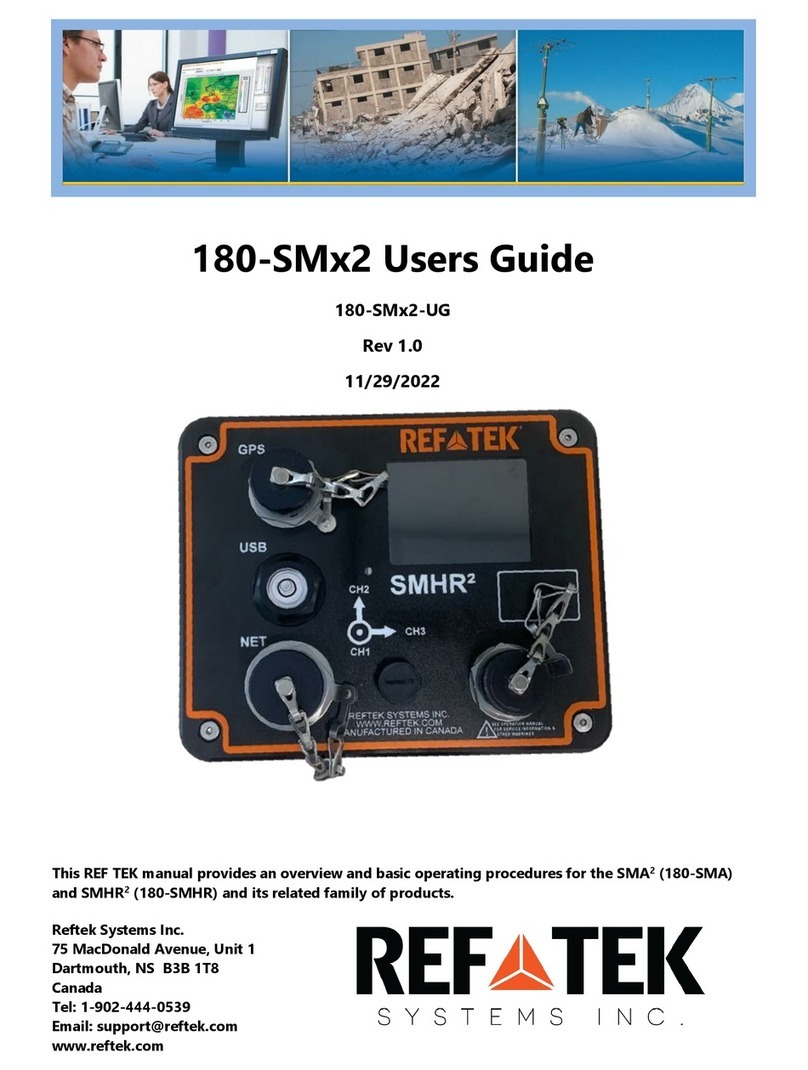
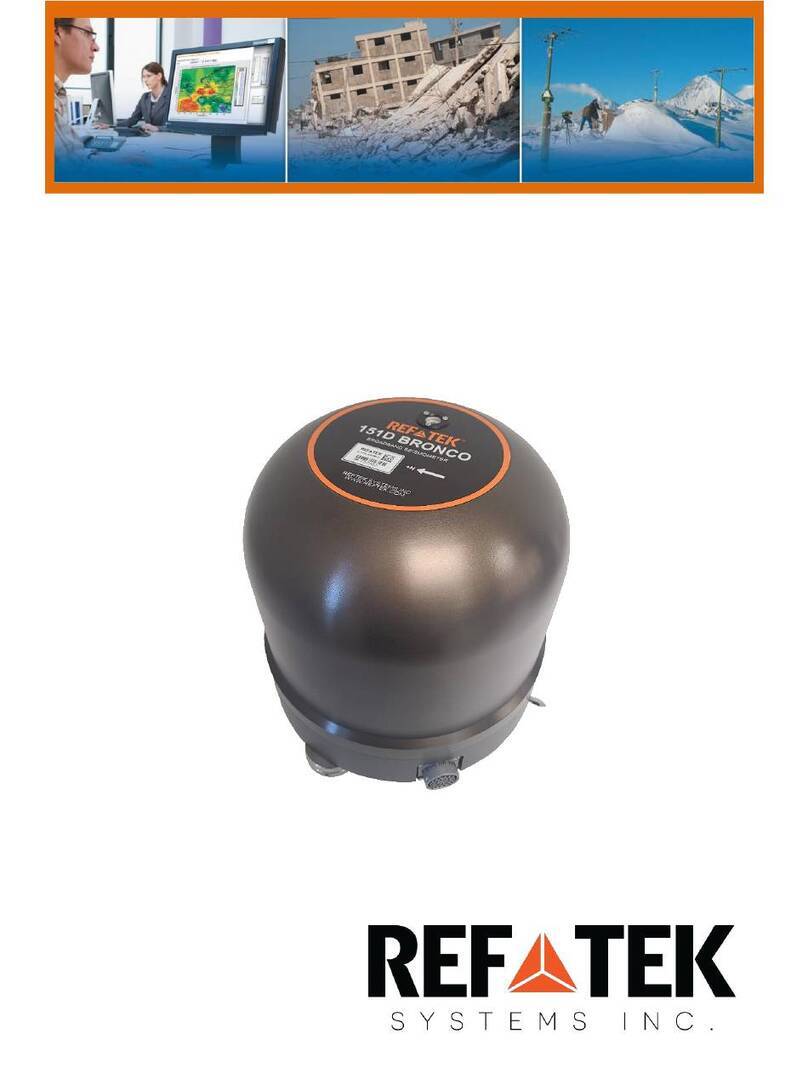
Reftek 130-MC User manual

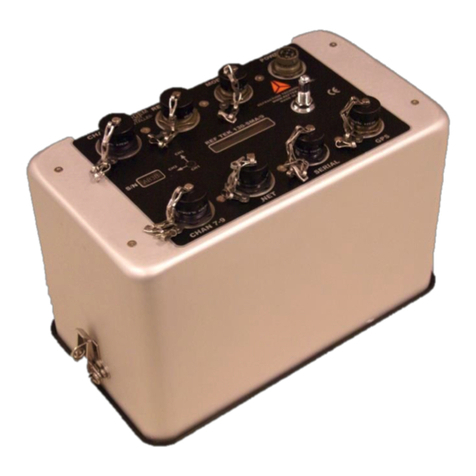
REF TEK 130 Multi-Channel Users Guide
96223-00-UG
Rev G
5/14/2021
This manual provides startup procedures for the 130-Multi-Channel Strong Motion Accelerograph
(MC12A)(97113-00)(MC18A)(97114-00) and its related products. Guidelines for initial communication with the
command line and modem are also provided.
Reftek Systems Inc.
75 MacDonald Avenue, Unit 1
Dartmouth, Nova Scotia
B3B 1T8
Support Phone: 1-902-444-0539
Email: support@reftek.com
www.reftek.com

Rev G REF TEK 130 Multi-Channel Users Guide 5/14/2021
96223-00-UG
ii Reftek Systems Inc.
Revision History:
Revision
Date
Reason for change
Pages
F
2014.09.26
Updated to Trimble Format
All
E
2013.11.05
Combined manuals into one manual
All
D
2012.10.01
Update sensor power (3.4.5)
All
2010.09.29
Modified for 3.2.8
All
2010.03.19
Modified for 3.2.2
Sect 2.3.1
C
2009.11.30
Updated for RT608
All
3.0.0CM
2009.10.20
Updated template
All
2009.05.19
Updated to 3.0.0CM
Iii and 5
B
2008.12.12
Imported to WORD
All
2008.02.08
Updated to 2.9.0
All
2007.09.07
Updated GUI to 2.0.4
All
A
2006.11.14
New Template
All
0.1
2006.06.13
Initial release
All
Copyright© 2021 Reftek Systems Inc.
All rights reserved. No part of this manual may be reproduced, copied or transmitted in any form
outside the approved recipient’s organization without written permission from Reftek Systems Inc.
Printed in CANADA

Rev G REF TEK 130 Multi-Channel Users Guide 5/14/2021
96223-00-UG
Reftek Systems Inc. iii
Notation Conventions:
The following notation conventions are used throughout REF TEK documentation:
Notation
Description
ASCII
Indicates the entry conforms to the American Standard Code for Information Interchange definition of
character (text) information.
Binary
Indicates the entry is a raw, numeric value.
Hex
Indicates hexadecimal notation. This is used with both ASCII characters (0 –9, A –F) and numeric values.
BCD
Indicates the entry is a numeric value where each four bits represents a decimal digit.
FPn
Indicates the entry is the ASCII representation of a floating-point number with n places following the
decimal point.
<n>
Indicates a single 8-bit byte. When the contents are numeric, it indicates a hexadecimal numeric value; i.e.
<84> represents hexadecimal 84 (132 decimal). When the contents are capital letters, it represents a
named ASCII control character; i.e. <SP> represents a space character, <CR> represents a carriage return
character and <LF> represents a line feed character.
MSB
Most Significant Byte of a multi-byte value.
MSbit
Most Significant Bit of a binary number.
LSB
Least Significant Byte of a multi-byte value.
LSbit
Least Significant Bit (bit 0) of a binary number.
YYYY
Year as a 4-digit number
DDD
Day of year
HH
Hour of day in 24-hour format
MM
Minutes of hour
SS
Seconds of minute
TTT
Thousandths of a second (milliseconds)
IIII
Unit ID number
n, nS
nano, nanoSecond; 10-9 = 0.000000001
u, uS
micro, microSecond; 10-6 = 0.000001
m, mS
milli, milliSecond; 10-3 = 0.001
K, KHz
Kilo, KiloHertz; 103 = 1,000
M, MHz
Mega, MegaHertz; 106 = 1,000,000
G, GHz
Giga, GigaHertz; 109 = 1,000,000,000
Kb, KB
Kilobit, KiloByte; 210 = 1,024
Mb, MB
Megabit, MegaByte; 220 = 1,048,576
Gb, GB
Gigabit, GigaByte; 230 = 1,073,741,824

Rev G REF TEK 130 Multi-Channel Users Guide 5/14/2021
96223-00-UG
iv Reftek Systems Inc.
REF TEK Support and update notifications
As a valued user of REF TEK equipment we would like to provide the best support
possible.
If you would like to know more about any of our REF TEK products and services,
please visit our website at https://reftek.com/technical-support.
On our support page, you can find information about submitting a support ticket,
downloading sensor calibration sheets and exploring training options.
You can contact us at:
Support Phone: 1-902-444-0539
Thanks,
Your REF TEK Support Team

Rev G REF TEK 130 Multi-Channel Users Guide 5/14/2021
96223-00-UG
Reftek Systems Inc. v
Contents
1MC18 Overview....................................................................................... 1
Introduction................................................................................................................................................1
Purpose of the 130-MC...............................................................................................................................3
130-MC System Connections......................................................................................................................4
1.3.1 Power Terminals ......................................................................................................................................5
1.3.2 GPS 232 Terminals ...................................................................................................................................6
1.3.3 GPS 485 Terminals ...................................................................................................................................6
1.3.4 MC-18 Interconnect.................................................................................................................................7
1.3.5 RT590 Connections and Jumpers.............................................................................................................9
1.3.6 Modem connector .................................................................................................................................10
1.3.7 130-MC Net Connector..........................................................................................................................11
1.3.8 Relay RT590 Connector..........................................................................................................................12
1.3.9 Channels 1-6 RT588 Connector..............................................................................................................13
1.3.10 Connection Diagram..........................................................................................................................14
1.3.11 Channels 7-12 RT588 Connector .......................................................................................................15
1.3.12 Channels 13-18 RT588 Connector .....................................................................................................16
Hardware Modularity ...............................................................................................................................17
1.4.1 130-MC List ............................................................................................................................................17
1.4.2 List of other Hardware...........................................................................................................................18
Frequently Asked Questions.....................................................................................................................18
Warranty Statement.................................................................................................................................19
Warranty/Non-Warranty Service .............................................................................................................19
Static sensitive device protection.............................................................................................................20
2Operation with command line............................................................... 21
Overview...................................................................................................................................................21
Getting started with your 130-MC ...........................................................................................................21
2.2.1 Minimal Hardware Connections ............................................................................................................22
2.2.2 Quick installation steps..........................................................................................................................22
DAS control overview ...............................................................................................................................23
General Recorder operation with command line control ........................................................................23
2.4.1 Example configuration...........................................................................................................................24
2.4.2 Power Considerations............................................................................................................................25
Port settings and modem communications..............................................................................................26
2.5.1 130-03 Command Port (Serial) ..............................................................................................................27
2.5.2 Ethernet Port .........................................................................................................................................27
2.5.3 Toss parameter......................................................................................................................................28
2.5.4 Internal modem port .............................................................................................................................29

Rev G REF TEK 130 Multi-Channel Users Guide 5/14/2021
96223-00-UG
vi Reftek Systems Inc.
2.5.5 Optional external modem port..............................................................................................................29
General GPS operations............................................................................................................................30
Formatting media .....................................................................................................................................31
2.7.1 Clear RAM on the 130-MC .....................................................................................................................31
2.7.2 Format a disk in the 130-MC..................................................................................................................31
2.7.3 Check status of a media device on the 130-MC.....................................................................................31
Modem configuration...............................................................................................................................32
2.8.1 Define a window for external modem power........................................................................................32
2.8.2 Define a delay time to initialize a modem .............................................................................................32
Modem setup ...........................................................................................................................................33
2.9.1 Set the baud rate ...................................................................................................................................33
2.9.2 Configure the modem initialization string .............................................................................................33
2.9.3 Modem dial out strings..........................................................................................................................34
2.9.4 Configure the modem hang-up string....................................................................................................34
3130-MC Settings with SMCC.................................................................. 35
Overview...................................................................................................................................................35
DAS Control with SMCC Overview............................................................................................................35
Port settings and modem communications..............................................................................................37
3.3.1 130-03 Command Port (Serial) ..............................................................................................................38
3.3.2 Ethernet Port .........................................................................................................................................38
3.3.3 Toss parameter......................................................................................................................................39
3.3.4 Internal modem port .............................................................................................................................39
3.3.5 Optional external modem port..............................................................................................................39
4Internal Modem support....................................................................... 41
Internal SLM modem and the RT580........................................................................................................41
Operating the 130-MC with the SLM Modem ..........................................................................................42
4.2.1 SLM Modem module .............................................................................................................................42
4.2.2 Modem features ....................................................................................................................................42
SMCC Modem Configuration....................................................................................................................42
4.3.1 Configure the modem initialization string .............................................................................................43
4.3.2 Modem Dial Out strings.........................................................................................................................43
4.3.3 Modem Power Time Windows ..............................................................................................................43
4.3.4 Delay Time/Speed..................................................................................................................................44
5130-03 Features ................................................................................... 45
Introduction..............................................................................................................................................45
Purpose of the 130-MC system ................................................................................................................46
130-03 Diagram ........................................................................................................................................46
5.3.1 Power connector....................................................................................................................................48
5.3.2 130-03 Serial Connector ........................................................................................................................48
5.3.3 GPS Connector .......................................................................................................................................49

Rev G REF TEK 130 Multi-Channel Users Guide 5/14/2021
96223-00-UG
Reftek Systems Inc. vii
5.3.4 Modem connector (Part of Relay connector) ........................................................................................49
5.3.5 130-03 Net Connector ...........................................................................................................................50
5.3.6 Relay connector .....................................................................................................................................51
5.3.7 Channels 1-6 connector .........................................................................................................................52
5.3.8 Channels 7-12 connector .......................................................................................................................53
5.3.9 Channels 13-18 connector.....................................................................................................................54
Hardware Modularity ...............................................................................................................................55
5.4.1 130-03 List of Hardware ........................................................................................................................55
5.4.2 130-03 Boards........................................................................................................................................56
6130-03 Assembly.................................................................................. 57
Introduction..............................................................................................................................................57
Disassembly of the 130-03 for service......................................................................................................57
Assembly of the 130-03............................................................................................................................58
130-03 REF TEK IP67 Test .........................................................................................................................58
6.4.1 Temporary Shallow Water Submersion Test Procedure........................................................................58
7Periodic Maintenance Operations ......................................................... 59
Introduction..............................................................................................................................................59
Replacing the Compact Flash™.................................................................................................................60
Connector Assembly & Maintenance .......................................................................................................62
RAM Backup Battery replacement ...........................................................................................................64
Disassembly of the 130-03 for service......................................................................................................65
Update firmware ......................................................................................................................................66
7.6.1 Update the firmware of a 130-MC using a PC .......................................................................................66
7.6.2 Update the firmware if at the 130-MC ..................................................................................................66
7.6.3 To transfer firmware to the 130-MC using RT130-SM...........................................................................66
7.6.4 Reset the 130-MC using RT130-SM .......................................................................................................67
Sample 130-03 LCD displays .....................................................................................................................68
8130-MC Internal cable drawings........................................................... 69
130-03 cable list........................................................................................................................................69
130-MC Cables..........................................................................................................................................69
9Index.................................................................................................... 71

Rev G REF TEK 130 Multi-Channel Users Guide 5/14/2021
96223-00-UG
viii Reftek Systems Inc.
This Page Left Intentionally Blank

Rev G REF TEK 130 Multi-Channel Users Guide 5/14/2021
96223-00-UG
Reftek Systems Inc. 1
1MC18 Overview
Introduction
This section describes operations and maintenance requirements for the REF TEK 130-MC
(MC12A - 12 Channel MC)(97113-00) OR (MC18A - 18 Channel MC)(97114-00). The 130-MC unit
meets the USGS Advanced National Seismic System (ANSS) specifications for strong motion
reference stations for deployment in urban areas. The 130-MC is the same as the 130-ANSS/02
but with important differences that include:
•Optional internal V.90 modem for event trigger, alarm notification, and dial-in.
•Battery charger for external or optional internal lead-acid batteries.
•Provides 3 relay closure contacts for user selectable parameters with external alarm
notification.
•The size of the 130-MC case allows the installation of internal batteries to provide backup
power for more than 48 hours.
The 130-MC is identical to the 130-SM except that it has a 12 or 18-channel 24-bit A-D converter
that has a typical dynamic range of more than 114 dB and a different oscillator for internal time
keeping.
This manual includes the following:
•An explanation of the general purpose of the 130-MC.
•Standard faceplate connection functions, pin-out, and associated cables drawings
•Hardware modularity
•Frequently asked questions about the 130-MC

Rev G REF TEK 130 Multi-Channel Users Guide 5/14/2021
96223-00-UG
2 Reftek Systems Inc.
130-MC18A
RT590 GPS
DAS
130-03/18
Triplite
Battery Location
Power Supply
RT588 RT588 -OR-
Sensor 1-6
Sensor 7-12 Sensor 13-18RT588
Misc Interface
or 130-03/12
Isobar
RT599

Rev G REF TEK 130 Multi-Channel Users Guide 5/14/2021
96223-00-UG
Reftek Systems Inc. 3
Purpose of the 130-MC
The REF TEK 130-MC combines the Third Generation Seismic Recorder (REF TEK 130-03). The 130-
MC system is housed in a rugged and versatile enclosure. The 130-MC is a rugged, portable, and
versatile data recorder. The modular design of their hardware and software allows you to
reconfigure the 130-MC system for various types of applications for continuously monitoring
earthquakes and other seismic events by thoroughly measuring strong earthquake shaking at
ground sites, in buildings and critical structures, and automatically broadcasting information
when a significant earthquake occurs. This allows immediate assessment of an impact.
Some specific uses include the following:
•Free field reference station for strong motion.
•Telemetry networks
•Aftershock studies
•Building arrays
•Structural monitoring
Mounting dimensions:

Rev G REF TEK 130 Multi-Channel Users Guide 5/14/2021
96223-00-UG
4 Reftek Systems Inc.
130-MC System Connections
The connections and cables used in the 130-MC enclosure are as follows:

Rev G REF TEK 130 Multi-Channel Users Guide 5/14/2021
96223-00-UG
Reftek Systems Inc. 5
Power Terminals
Power is supplied to the 130-MC system through one 110 AC power connector. The hardware
connection diagram on the previous page shows typical connections for the 130-MC. The
following chart details individual connection to the terminal block (TB1) and charger.
Note: The 130-8271 cable provides the input diode drop required to isolate the battery from the charger and detect
the loss of building AC.
CAUTION:. Disk operations are suspended when the input voltage drops below 9.0 Volts and
are re-enabled when the voltage goes above 10.0 Volts. (Version 2.9.6 or later) (See 3.0.0
CPU Release Notes)
Note: Firmware upgrades are not performed when the power is below 10.0 Volts. (Version 2.9.6 Release or later)

Rev G REF TEK 130 Multi-Channel Users Guide 5/14/2021
96223-00-UG
6 Reftek Systems Inc.
GPS 232 Terminals
The GPS connector allows an external clocking device, such as the REF TEK 130-GPS\01 Global
Positioning System clock to be connected. Also supported is input and output for GPS 485. This
allows GPS to come into the 130-MC and be output to GPS 485.
GPS 232
Terminals
RT590 Connector Cable J6
MC Pin
Pin Desc
Electrical Desc
Voltage
Range
GPS 232
TB5
1
GPS 1Hz
Input Pulse
0-5 Volts
2
GND
PWR/Signal GND
3
GPS RX
Output RS232
±12 Volts
4
GND
5
GPS TX
Input RS232
±12 Volts
6
PWR
Selectable 15V or
24V
15 or 24 Volts
7
EARTH
8
No Connect
9
EARTH
GPS 485 Terminals
Also supported is input for GPS 485. This allows usage of a single GPS to come into one 130-MC
and be output to multiple 130-MC units.
GPS 485
Terminals
RT590 Connector Cable J6
MC Pin
Pin Desc
Electrical Desc
Voltage
Range
GPS 485
TB8
1
RX 485 +
Output
RS-485
2
RX 485 -
Output
RS-485
3
TX 485 +
Input
RS-485
4
TX 485 -
Input
RS-485
5
1 Hz 485 +
Input
RS-485
6
1 Hz 485 -
Input
RS-485
7
GND
8
PWR
Selectable 15V or
24V
9
EARTH

Rev G REF TEK 130 Multi-Channel Users Guide 5/14/2021
96223-00-UG
Reftek Systems Inc. 7
MC-18 Interconnect
These connections allow interconnect among multiple MC-18s.
GPS 485
Terminals
RT590 Connector Cable J6
MC Pin
Pin Desc
Electrical Desc
Voltage
Range
TRIGGER
TB6
1
EX 485 +
Input/Output
RS-485
2
EX 485 -
Input/Output
RS-485
3
GND
GPS 485 OUT
TB7
1
TX 485 +
Output GPS_TX
RS-485
2
TX 485 -
Output GPS_TX
RS-485
3
1 Hz 485 +
Output 1Hz
RS-485
4
1 Hz 485 -
Output 1Hz
RS-485
5
GND
6
IRIGE
Output
TTL
7
GND
8
EARTH
9
No Connect

Rev G REF TEK 130 Multi-Channel Users Guide 5/14/2021
96223-00-UG
8 Reftek Systems Inc.

Rev G REF TEK 130 Multi-Channel Users Guide 5/14/2021
96223-00-UG
Reftek Systems Inc. 9
RT590 Connections and Jumpers

Rev G REF TEK 130 Multi-Channel Users Guide 5/14/2021
96223-00-UG
10 Reftek Systems Inc.
Modem connector
The modem connector provides connections for the 130-MC internal modem. The modem
connector is provided in order to connect the internal modem to the Plain-Old-Telephone-
Service. The 130-8279 telephone line cable from the 130-03 connector connects to the Tripplite
Isobar connector.
130-03
Connector
Tripplite
Connector
MC Pin
Pin Desc
Electrical Desc
Voltage Range
Relay/Modem
130-8279
A
TIP
Telephone Line
B
RING
Telephone Line

Rev G REF TEK 130 Multi-Channel Users Guide 5/14/2021
96223-00-UG
Reftek Systems Inc. 11
130-MC Net Connector
Communications between the 130-MC and a remote system using either external TCP/IP and/or
an optional external Modem occur across the 130-MC NET connector on the RT590 board. The
RJ45 connection (J4) allows a cable with two connections, one for Ethernet and one for serial
communications. The internal modem must be removed before using an external modem. See
the Command Line Theory of Operations for a procedure on removing the internal modem.
CAUTION: A 130-MC is shipped pre-configured with a default IP address. Be sure to change
this address before connecting the 130-MC to an Ethernet port. Any IP addresses on one of
the same subnets, as the 130-MC unit, may connect using FTP and/or the command socket.
However, the 130-MC unit restricts the external IP addresses from which it will accept
connections, to the equivalent of a Class C subnet containing the RTP host. If no RTP host is
set for an interface, no connections can be established to the unit from outside its subnet.
The 130-MC uses a 10BaseT Ethernet chip. The 130-MC Ethernet port may not work when
connected to all 100BaseT and some 10/100BaseT Ethernet hubs.
This connector also functions as the point of input for the external trigger. It also serves as the
point of output for an event detection (trigger out) pulse. There is also a 12VDC nominal input on
this connector to allow for lab setup via Ethernet using only this connector.

Rev G REF TEK 130 Multi-Channel Users Guide 5/14/2021
96223-00-UG
12 Reftek Systems Inc.
Relay RT590 Connector
The relay terminals on the 130-MC provides three relay closures for certain software set able
alarm conditions. Both Normally Open and Normally Closed contacts are provided on the relay
connector for each of the three relays. A hardware jumper is provided to change the relay
contacts from Normally De-energized (default) to Normally Energized. The relay contacts are
rated at 120 Volts AC and 30 Volts DC. The relay amp rating is equal to 1 amp. These alarm relays
can be configured using the RL command or on the Relay section of the GUI. See the SMCC Users
Guide or Command Line Reference for more information.
RT590 Terminals
Connector
MC Pin
Pin
Desc
Electrical Desc
Voltage Range
Relay 1
TB1
1
NO
Relay 1
Normally Open Contact
0-120V AC
0-30V DC
2
COM
Relay 1
Common Contact
3
NC
Relay 1
Normally Closed Contact
Relay 2
TB2
1
NO
Relay 2
Normally Open Contact
0-120V AC
0-30V DC
2
COM
Relay 2
Common Contact
3
NC
Relay 2
Normally Closed Contact
Relay 3
TB3
1
NO
Relay 3
Normally Open Contact
0-120V AC
0-30V DC
2
COM
Relay 3
Common Contact
3
NC
Relay 3
Normally Closed Contact
Note: There is an optional jumper (JP3 located near the relay connector) that can be installed on the RT580 Lid
board in order to set the three provided relays as normally energized.
JP3
Table of contents
Other Reftek Measuring Instrument manuals
Popular Measuring Instrument manuals by other brands

KROHNE
KROHNE OPTIWAVE 400 Series Supplementary instructions

Dostmann Electronic
Dostmann Electronic 31.5008.02 Operating instruction

Anritsu
Anritsu Site Master S251C user guide

Fluke Calibration
Fluke Calibration KIT-EMM300 instructions

Norcross
Norcross DS900SP instruction manual

Grace Industries
Grace Industries SuperCELL SC500-LW-GPS User information