manuals.online logo
Brands
  1. Home
  2. •
  3. Brands
  4. •
  5. Dorma
  6. •
  7. Door Opening System
  8. •
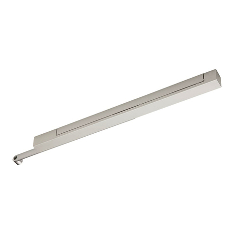
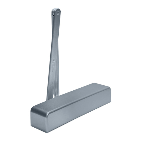
  9. Dorma 8916 FT User manual

Dorma 8916 FT User manual

This manual suits for next models

3

Other Dorma Door Opening System manuals

Dorma 96 GSR-EMF User manual

Dorma

Dorma 96 GSR-EMF User manual

Dorma TS93-5 PKT 90/119 User manual

Dorma

Dorma TS93-5 PKT 90/119 User manual

Dorma BEYOND User guide

Dorma

Dorma BEYOND User guide

Dorma BTS 65 User manual

Dorma

Dorma BTS 65 User manual

Dorma AGILE 150 User manual

Dorma

Dorma AGILE 150 User manual

Dorma AGILE 150 User manual

Dorma

Dorma AGILE 150 User manual

Dorma TS 92 G User manual

Dorma

Dorma TS 92 G User manual

Dorma 7400 AO8 User manual

Dorma

Dorma 7400 AO8 User manual

Dorma ES 200 T Easy Manual

Dorma

Dorma ES 200 T Easy Manual

Dorma ES 200 User manual

Dorma

Dorma ES 200 User manual

Dorma EMR Series User manual

Dorma

Dorma EMR Series User manual

Dorma AGILE 150 User manual

Dorma

Dorma AGILE 150 User manual

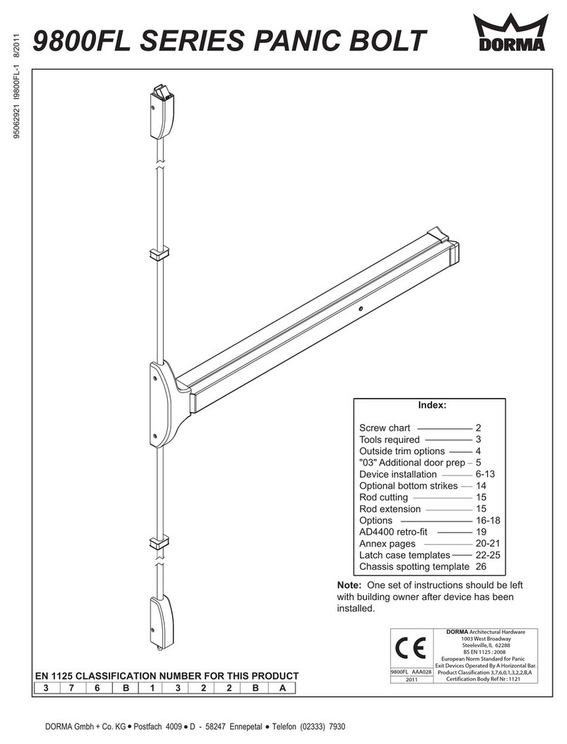
Dorma 9800FL Series User manual

Dorma

Dorma 9800FL Series User manual
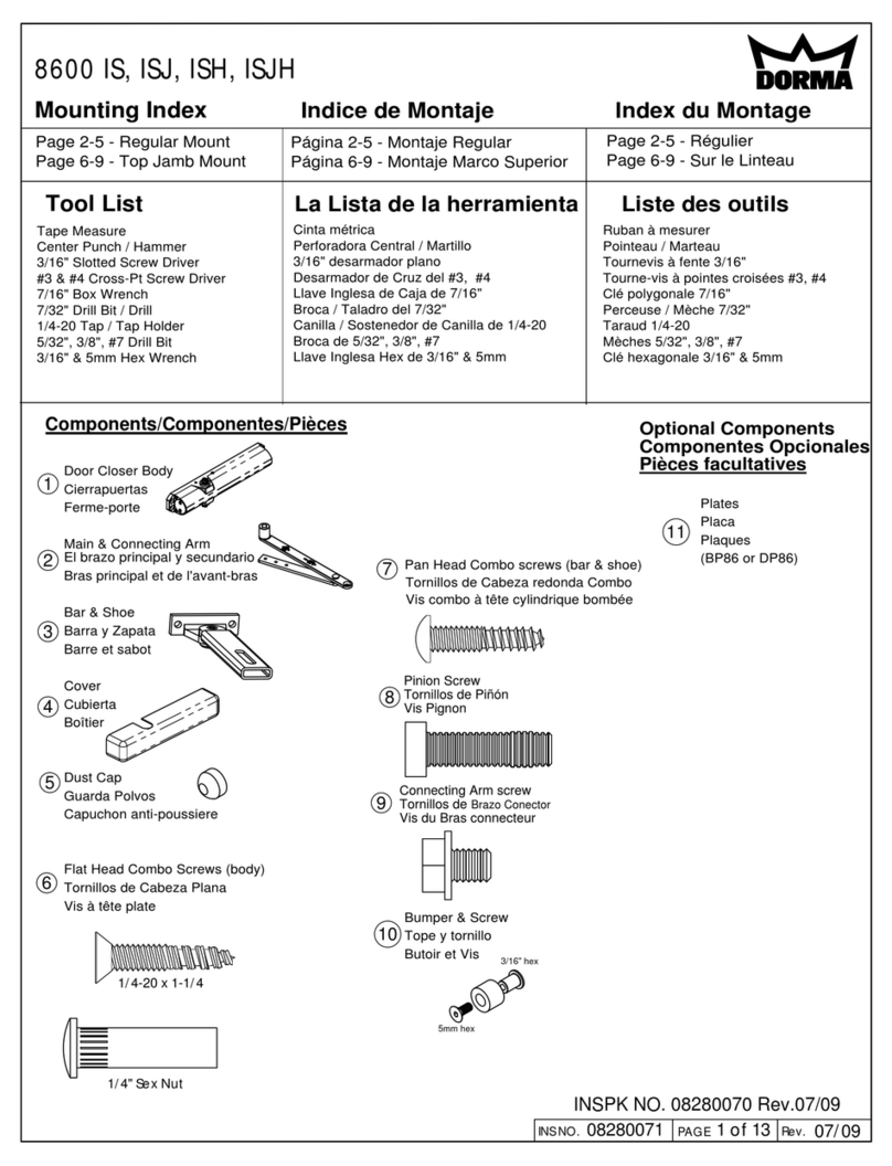
Dorma 8616 PH User manual

Dorma

Dorma 8616 PH User manual

Dorma STA Series User manual

Dorma

Dorma STA Series User manual

Dorma 8616 FH User manual

Dorma

Dorma 8616 FH User manual

Dorma EM 508 Series User manual

Dorma

Dorma EM 508 Series User manual

Dorma 7300 Series User manual

Dorma

Dorma 7300 Series User manual

Dorma 8600 IS User manual

Dorma

Dorma 8600 IS User manual
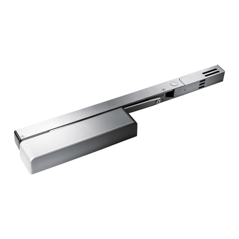
Dorma 8600 DS User manual

Dorma

Dorma 8600 DS User manual

Dorma 8956 T PKT 90 User manual

Dorma

Dorma 8956 T PKT 90 User manual
Dorma ED900 User manual

Dorma

Dorma ED900 User manual

Dorma G-SR BG User manual

Dorma

Dorma G-SR BG User manual

Dorma UNIVERSAL Motion User manual

Dorma

Dorma UNIVERSAL Motion User manual

Popular Door Opening System manuals by other brands

Mobeye Call-Key MCK100 installation manual

Mobeye

Mobeye Call-Key MCK100 installation manual

SALICE Lapis Assembly instructions

SALICE

SALICE Lapis Assembly instructions

Cal-Royal N-F77CVR Installation instruction

Cal-Royal

Cal-Royal N-F77CVR Installation instruction

Scrigno OPEN1000 Assembly manual

Scrigno

Scrigno OPEN1000 Assembly manual

BFT WIND RMB 130B 200 installation manual

BFT

BFT WIND RMB 130B 200 installation manual

Alecto ADI-250 user manual

Alecto

Alecto ADI-250 user manual

Besam Swingmaster MP Installation, adjustment and maintenance instructions

Besam

Besam Swingmaster MP Installation, adjustment and maintenance instructions

Assa Abloy SARGENT 1431 Series instructions

Assa Abloy

Assa Abloy SARGENT 1431 Series instructions

GAL MOVFR Quick setup

GAL

GAL MOVFR Quick setup

Häfele Finetta T 70 VF manual

Häfele

Häfele Finetta T 70 VF manual

AGS D-PL Instructions for fitting, operating and maintenance

AGS

AGS D-PL Instructions for fitting, operating and maintenance

Stanley MA900ñ Installation and owner's manual

Stanley

Stanley MA900ñ Installation and owner's manual

WITTUR Hydra Plus UD300 Instruction handbook

WITTUR

WITTUR Hydra Plus UD300 Instruction handbook

Alutech TR-3019-230E-ICU Assembly and operation manual

Alutech

Alutech TR-3019-230E-ICU Assembly and operation manual

Pamex KT-INP35 Installation instruction

Pamex

Pamex KT-INP35 Installation instruction

MPC ATD ACTUATOR 50 ATD-313186 Operating and OPERATING AND INSTALLATION Manual

MPC

MPC ATD ACTUATOR 50 ATD-313186 Operating and OPERATING AND INSTALLATION Manual

Chamberlain T user guide

Chamberlain

Chamberlain T user guide

Fireco Dorgard operating guide

Fireco

Fireco Dorgard operating guide

manuals.online logo
manuals.online logoBrands
  • About & Mission
  • Contact us
  • Privacy Policy
  • Terms and Conditions

Copyright 2025 Manuals.Online. All Rights Reserved.

1 of 3
INS NO. Rev.
08280171 09/09
PAGE
www.dorma-usa.com 1-800-523-8483
HINGES
8916/8956 FT, FTH
1
2
4
FLUSH TRACK INSTALLATION PUSH SIDE MOUNT
AND ACCESSORY PLATE BP89
WOOD FRAME
METAL FRAME
QTY
(4)
(4)
QTY
as shown. Arrow on plate to point toward arm
BP89 Plate applications only. Attach plate to frame
attachment.
3latch valves facing hinges.
Attach closer to frame or plate with sweep and
(RIGHT HAND DOOR)
(LEFT HAND DOOR)
SLIDE SHOE
HOLD OPEN MECHANISM
Insert slide shoe, rubber stop and end blocks
into track and attach track to door.
NOTE: MOUNTING SCREWS PASS THROUGH END
Assemble track and attach to door.
stop, hold open mechanism, and end blocks into
and tighten securely. Insert slide shoe, rubber
Attach arm to slide shoe using screw supplied
C
END BLOCK
C HINGES
track and attach track to door.
(FTH UNITS ONLY)
RUBBER STOP
RUBBER
BLOCKS.
(FT UNITS ONLY)
END BLOCK
END BLOCK
SLIDE SHOE
END BLOCK
HINGES
M6 HEX KEY
HINGES
C
IMPORTANT :
STOP
ARM TO SLIDE SHOE
(1)
QTY
NOTE: HOLD OPEN MECHANISM AND SLIDE SHOE MUST
BE INSTALLED WITH ARROWS POINTING AWAY
FROM THE DOOR HINGES. (ARROWS ARE
STAMPED ON SLIDE SHOE & HOLD OPEN
MECHANISM)
(2)
QTY
(2)
QTY
OR
(METAL)
(WOOD)
WOOD FRAMES
METAL FRAMES
QTY
(4)
(4)
QTY
PLATE
(4)
QTY
according to appropriate template.
Determine hand of door. Prepare door and frame
(REFERENCE UNIT CARTON FOR ACCESSORIES AND
OPTIONS SUPPLIED)
LISTINGS.
IDENTIFIED IN THE INDIVIDUAL DOOR MANUFACTURER'S
DOORS, UNLESS AN ALTERNATIVE METHOD IS
WOOD OR PLASTIC FACED COMPOSITE TYPE FIRE
OF COMPONENTS TO UNREINFORCED DOORS AND TO
CAUTION: SEX NUTS ARE REQUIRED FOR ATTACHMENT
REVERSE BEVEL
RIGHT HAND DOOR
LEFT HAND DOOR
REVERSE BEVEL
RIGHT HAND LEFT HAND
L
HINGES
L
CC
INSPK NO. 08280170 Rev.09/09
6
5
Adjust according to chart.
ADJUSTER
FULL TURNS
OF SPRING
0
+4
+12
FULL TURNS
OF SPRING
ADJUSTING NUT
ADJUST SPRING TENSION ACCORDING TO THE FOLLOWING CHART.
8916
8956
CLOSER
ULC LABELED UNITS ONLY
TYPE
200
200 6
5
60
SIZE
SPRING
DOOR
WEIGHT
150
125
MAX.
4
NON-BARRIER-FREE OPENINGS -
TYPE
8916
8956
CLOSER
INTERIOR
2'-6"
3'-6"
3'-0"
4'-0"
+4
0
+12
0
DOOR WIDTH
5
6
6
4
SPRING
SIZE
Take an opening force reading from
the pull on the door. If required, adjust the spring tension
to meet the barrier-free requirement. Maximum number of
adjusted to meet barrier-free forces may not have sufficient
power to reliably close and latch the door.
turns counter clockwise=8. Maximum number of turns
clockwise =14. Depending on opening conditions, a door
BARRIER-FREE OPENINGS -8916 ONLY
ADJUSTER
Adjust spring tension, if required, using a 1/4" wrench.
8956 supplied with size 6 setting.
8916 supplied with size 4 spring setting.
SPRING TENSION
CRITICAL
NOTE:
+
-
3'-6" +6 6+
+6
6+
250
Install main arm
onto bottom pinion. Fasten securely with pinion
With main arm parallel to door, place main arm
Rotate pinion 45° AWAY FROM HINGE edge of door.
Place wrench on top
pinion.
45°
screw.
* Viewed from bottom of door
RIGHT HAND IS A MIRROR IMAGE.
INSTALLATION SHOWN.
NOTE: LEFT HAND DOOR
PINION SCREW
L HINGE
C
PINION
6mm HEX KEY
ROTATE
PINION
45°
(1)
QTY
08280171 2 of 3 09/09
INS NO. PAGE Rev.
M2.5 HEX KEY
Place the hold open
mechanism in desired
position and tighten screw.
SNAP VALVE ADJUSTMENT
WRENCH INSIDE COVER
7
9
8
To adjust hold open
force, turn clockwise to
increase force, and
counter clockwise to
To enable hold open,
push the white slide into
the hold open mechanism.
To disable hold open,
A
B
C
(HOLD OPEN UNITS ONLY)
Set hold open.
weaken force.
M2.5 HEX KEY
OFF ON
pull the white slide away
from hold open mechanism.
BACKCHECK OR DELAYED ACTION
NOTE: DELAYED ACTION IS AN OPTIONAL FEATURE.
DECREASE
control when extra time is required to pass through
Optional delayed action offers additional closing speed
the door. All valve adjustments are made with a 3/32"
CAUTION: DO NOT REMOVE VALVES.
DELAYED ACTION
BACKCHECK RANGE
SWEEP (SPEED)
INCREASE
(SPEED)
LATCH
RANGE
(TIME)
ACTION
DELAYED
hex key.
SWEEP & LATCH
POSITIONING VALVE
BACKCHECK (INTENSITY)
RANGE
LATCH
SWEEP
RANGE
DECREASE
INCREASE
should take a minimum of 1.5 seconds.
Closing time from 15° to fully closed (latch range)
generally adjusted to take a minimum of 3 seconds.
Closing time from 90° to 15° (sweep range) is
Adjust sweep and latch valves.
(2)
TAB
QTY
NOTE: LEFT HAND INSTALLATION SHOWN. RIGHT
HAND IS A MIRROR IMAGE.
Placecoverovercloserandfastensecurelywith
Placetabincoverslotoppositemainarm.
screwsprovided.
08280171 3 of 3 09/09
INS NO. PAGE Rev.