Optional Cover Plate with Gasket*
Model G4/G5
QR Gasket
Cover Plate
(cULus Listed)
Model G4/G5 SR Gasket
Cover Plate
(FM Approved)
* Model G4/G5 QR Gasket and Model G4/G5 SR Gasket cover
plates are sold as assembled units including both the cover
plate and gasket. Model G4 /G5 QR Gasket and Model G4 /G5
SR Gasket cover plates and gaskets are not interchangeable.
Installation Instructions
Model G5-56 Dry sprinklers must only be installed in stan-
dard (ANSI B 16.3 class 150 and ANSI B 16.4 class 125)
pipe tees in the horizontal position, even at branch line ends.
Model G5-56 Dry sprinklers shall not be installed into elbows
or pipe couplings located on drop nipples to the sprinklers.
In all installations, including into CPVC piping, the dry sprin-
kler shall be installed with protrusion into the fitting in accor-
dance with the installation diagrams in this Bulletin.
Installation of the Model G5-56 Dry sprinkler is not recom-
mended in copper pipe systems, as this may reduce the
life expectancy of the sprinkler. Do not install Model G5-56
Dry sprinklers with the standard (long) inlet fitting into CPVC
adapter fittings or tees that have an internal obstruction (see
Fig. 3); this will damage the sprinkler, the fitting, or both. A
short inlet (“PL”) version of the Model G5-56 Dry sprinkler is
available for use in existing installations with CPVC adapter
fittings or tees having an internal obstruction; Model G5-56
sprinklers with the short inlet fitting shall not be used on dry-
pipe sprinkler systems. The Model G5-56 Dry sprinkler and
the cover plate assembly are not intended for installation in
corrosive environments, including, but not limited to, those
with salt aerosols or chlorine.
Model G5-56 Dry sprinklers must be installed with the Ex-
posed Minimum Barrel Length required by Fig. 2 located in
a Heated Area. Do NOT install the sprinkler in ceilings which
have positive pressure in the space above.
The following steps must be followed for
installation:
1. Cut a 25
/
8-inch (67mm) diameter hole in the ceiling di-
rectly in-line with the outlet of the tee.
2. Apply pipe joint compound or Polytetrafluoroethylene
(PTFE) tape to the threads of the sprinkler’s inlet fitting.
3. A protective cap is provided to protect the drop-down
sprinkler deflector from damage which could occur dur-
ing construction before the cover plate is installed. The
cap is factory installed inside the sprinkler cup. Remove
the cap to install sprinkler, Step 4, then reinstall cap until
the cover plate is installed.
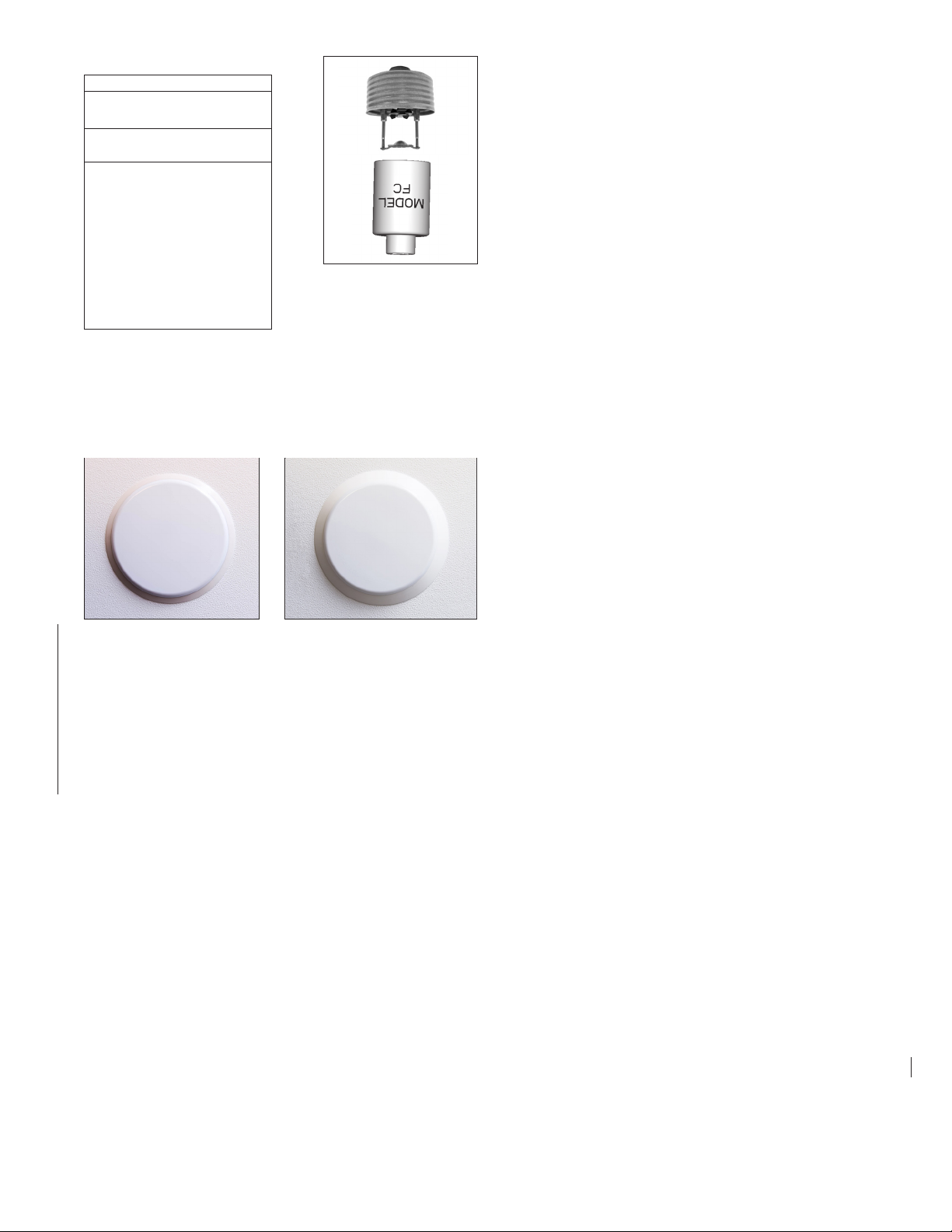
4. Install the sprinkler in the tee using the Model FC
wrench. The Model FC wrench has a socket drive which
is inserted into the sprinkler’s cup and around the body
of the sprinkler prior to installation of the sprinkler. Do
NOT wrench any of the part of the sprinkler/cup assem-
bly. The sprinkler is then tightened into the pipe fitting
to achieve a leak free connection. The recommended
minimum to maximum installation torque is 22-30 lb-ft
(30 – 40 N-m). When inserting or removing the wrench
from the sprinkler/cup assembly, care should be taken
to prevent damage to the sprinkler. Reinstall the protec-
tive cap following installation of the sprinkler, until the
cover plate is installed.
a. Alternatively, where access to the outer tube of the
sprinkler is available, the Model G5-56 Dry sprin-
kler may be installed using a pipe wrench. The
protective cap should not be removed to install
the sprinkler with a pipe wrench. The pipe wrench
shall only be permitted to interface with the steel
outer tube portion of the sprinkler (Item #8 in
Fig. 4). Do NOT wrench any other portion of the
sprinkler/cup assembly. A pipe wrench can install
the sprinkler into the fitting with a large amount
of torque; consideration should be given to the
need for future removal of the sprinklers because
the installation torque will have to be matched or
exceeded to remove the sprinkler. The recom-
mended minimum to maximum installation torque
is 22-30 lb-ft (30 – 40 N-m).
5. To install the cover plate, remove the protective cap and
install the cover plate by hand turning the cover in the
clockwise direction until it is tight against the ceiling. For
Model G4 /G5 QR Gasket and Model G4 /G5 SR Gas-
ket cover plates, the gasket should be attached to the
flange of the cover plate skirt only. Do not glue the gas-
ket in place or allow the gasket to overlap both the cover
plate and the flange of the skirt.
Model FC
Sprinkler Wrench
3.
Cover Plate Finishes
Standard Finishes
White Paint
Chrome
Special Application
Finishes
Off White Paint
Black Paint
Custom Color Paint – Specify(1)
Raw Brass (Lacquered)
Bright Brass
Finished Bronze
Black Plated
Satin Chrome
Stainless Steel Clad(2)
(1) Custom color paint is semi-gloss, unless specified otherwise.
(2) Stainless steel clad cover plates are Type 316 Stainless Steel on the finished
side and C102 Copper Alloy on the back side. Cover plates are not listed
or approved as corrosion resistant. Stainless steel clad cover plates are not
available perforated.