manuals.online logo
Brands
  1. Home
  2. •
  3. Brands
  4. •
  5. Reliable
  6. •
  7. Security System
  8. •
  9. Reliable Model C Owner's manual

Reliable Model C Owner's manual

Bulletin 613G
Listed by Underwriters Laboratories, Inc.
Approved by Factory Mutual Research
Corporation, and other fire insurance and
governmental agencies in the United
States and foreign countries.
Model C
Mechanical
Sprinkler Alarm
Instructions for
Installation, Operation, Care
and Maintenance
The Reliable Automatic Sprinkler Co., Inc., 525 North MacQuesten Parkway, Mount Vernon, New York 10552
valve, the strainer shall be located at the outlet of the
retarding chamber unless the retarding chamber is
provided with an approved integral strainer in its outlet.
The piping to the mechanical alarm should be pitched
to allow proper drainage back through the strainer.
Alarm, dry pipe and deluge valve trimmings provide
the proper drain outlet. Refer to respective valve
bulletins for installation of trimmings.
The 1″(25mm) drain outlet should discharge into an
open drain.
No single mechanical alarm should be connected to
more than three sprinkler systems and they should be
located in the same fire area. A ¾ ″NPT (R¾) swing
check valve must be located in each alarm line near the
junction(s) going to the Mechanical Alarm. This will
assure that water flowing from the alarm port of the
opened Valve will go directly to the water motor. A hole
approximately 18″(3.2mm) diameter should be drilled
through the clapper of each check valve near the center.
Operation
When an alarm (wet), dry pipe or deluge valve is
operated due to fire, water flows through the ¾ ″(20mm)
strainer, and ¾ ″(20mm) piping that connects the
mechanical sprinkler alarm to the valve. On entering the
mechanical sprinkler alarm inlet, the water passes
through the nozzle and impinges against the gong
producing a continuous piercing alarm. The water, after
impinging against the pelton wheel, drains through the 1″
(25mm) drain outlet in the body housing.
The alarm continues to sound as long as water is
flowing through the sprinkler system. It may be shut off
by closing the alarm control valve located in the alarm line
connecting the mechanical sprinkler alarm with the alarm
(wet), dry pipe or deluge valve. Normally, the alarm
control valve must be sealed in the open position.
The Model C Mechanical Sprinkler Alarm is self setting
after each operation, eliminating the need of removing
cover plates, etc. to reset internal mechanisms.
Installation Instructions
The Model C Mechanical Sprinkler Alarm shall be
located as near the alarm (wet), dry or deluge valve as
practicable in order to avoid long runs or many fittings in
the piping. The total length of the pipe should not exceed
75 feet ( 22.9m ) nor shall the mechanical sprinkler alarm
be located over 20 feet (6.1m) above the valve. If
absolutely necessary to exceed 75 feet (22.9 m), the pipe
line to the mechanical sprinkler alarm shall be increased
one or more sizes to compensate for loss of pressure due
to hydraulic friction.
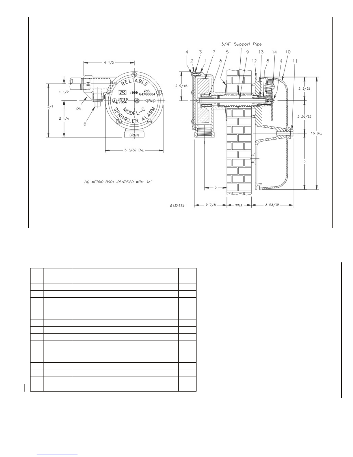
1. Locate and cut hole in building wall for connecting ¾″
(20mm) support pipe of appropriate length wall
thickness plus 1″(25mm).
2. Assemble the support pipe to the Wall Plate
(95106603) without removing the Gong (93806612)
and position this assembly on the outside wall with the
support pipe through the wall.
3. Remove the Body Cover (92106603), Cover Gasket
(93706602), and Pelton Wheel (97006603) from the
Body (91006603).
4. Place the Wall Support Washer (96906603) over the
support pipe as shown in the assembly drawing and
screw the Body onto the support pipe until the entire
assembly is aligned and secure to the wall.
5. Slip the Drive Shaft (96206603) thru the support pipe
and into the Drive Shaft Adapter (90086601). Rotate
the drive shaft to make sure it’s properly inserted (the
gong will alarm). Mark and cut the drive shaft where it
projects from the hub in the body.
6. With the drive shaft in place, make sure the Nylon
Bearing (90506603) is in the hub and insert the Pelton
Wheel through this onto the drive shaft. Spin the
Pelton Wheel to ensure that the assembly is free and
that the gong alarms.
7. Replace the Body Cover and Cover Gasket.
8. Connect alarm inlet to the alarm (wet), dry pipe or
deluge valve using galvanized or brass pipe of size
not less than ¾ ″ (20mm). An approved ¾ ″(20mm)
strainer is included for installation near the alarm outlet
of the alarm (wet), dry pipe or deluge valve. When a
retarding chamber is used in connection with an alarm
2.
Model C Mechanical Sprinkler Alarm
Item Part Number Description Qty.
Req’d
191006603Body1
292106603Body Cover 1
393706602Cover Gasket 1
495606604Body Cover & Adapter Screw6
596906603Wall Support washer 1
698604402Clean-out Plug1
797006603Pelton Wheel 1
890506603Bearing2
996206603Drive Shaft, 18 ″1
1093806612Gong1
1191106601Gong Bolt 1
1295106603Wall Plate1
1390086601Driver Shaft Adapter 1
1473020063Striker Assembly1
1578650200Strainer, ¾″24 Mesh (not shown) 1
List of Model C Mechanical Sprinkler Alarm Parts
3.
Should replacement parts be needed, use only genuine Reliable made parts.
When ordering, specify part number, name, model and serial number of the
unit.
Maintenance
1. Sprinkler System – See NFPA 25 pamphlet –
Inspection Testing and Maintenance of Sprinkler
Systems.
2. Strainer – Refer to respective alarm, dry pipe or
deluge valve bulletins.
A ¾″(20mm) strainer is located in the alarm line.
Periodic removal and cleaning of the strainer will
eliminate accumulation of trash and scale which
can impair the flow of water, thereby preventing
proper operation of the sprinkler alarm.
3. Clean-out – The Clean-out Plug (98604402) in the
water motor should be removed periodically to
remove any accumulation of trash and scale that may
have passed through the strainer.
4. Bearings – These are nylon and do not require
lubrication.
Inspection
1. Check inside of gong for accumulation of trash,
nests, etc.
2. Be sure the gong bolt (91106601) is secure.
3. Be sure that the ¾″(20mm) strainer is clean.
Note: See “Maintenance.”
4. False alarms – Refer to Alarm Valve Bulletins 407
or 408.
Testing
1. Alarm Valve Installations
Refer to Alarm Valve Bulletins 407, 408 or 409.
The mechanical sprinkler alarm may be tested without
disturbing the alarm valve by opening the alarm test valve
located in the piping line connecting it to the alarm valve
inlet side.
To test the mechanical sprinkler alarm and the alarm
valve, open the 1 ″(25mm) inspector’s test connection.
This connection is usually located at the end or top line of
the system and its opening is equivalent to the fusing of
one automatic sprinkler.
2. Dry Pipe Valve Installations
Refer to Dry Pipe Valve Bulletins 350, 353 or 354.
To test the mechanical sprinkler alarm, open the alarm
test valve located in the piping connecting the sprinkler
alarm to the dry pipe valve inlet side.
Note: After testing, it is necessary to drain the water
from the alarm line – refer to the dry pipe valve inspection
and testing procedure.
3. Deluge valve installations
Refer to Deluge Valve Bulletins 501 or 503.
Test the mechanical sprinkler alarm by opening the
alarm test valve located in the piping line connecting the
sprinkler alarm to the deluge valve inlet side. After the
test is completed, push in on the plunger of the
mechanical ball drip valve until all water has drained from
the alarm line.
The equipment presented in this bulletin in accordance with the latest pertinent Standard of the National Fire Protection Association, Factory Mutual Research
Corporation, or other similar organizations and also with the provisions of governmental codes or o rdinaire whenever applicable.
Products manufactured and distributed by Reliable have been protecting life and property for over 8 0 years, and are installed and serviced by the most highly
qualified and reputable sprinkler contractors located throughout the United States, Canada and foreign countries.
Manufactured byThe Reliable Automatic Sprinkler Co., Inc.
800.431.1588Sales Offices
800.848.6051Sales Fax
914.668.3470Corporate Offices
www.reliablesprinkler.comInternet Address
Revision lines indicate updated or new data.
E.G. Printed in U.S.A. 01/01 P/N 9999970060

Popular Security System manuals by other brands

Viking VS 2625 Operation manual

Viking

Viking VS 2625 Operation manual

WiLife Pro WLPC-810i Setup guide

WiLife

WiLife Pro WLPC-810i Setup guide

Smanos H400 user manual

Smanos

Smanos H400 user manual

Link4 iPonic 624 Alert user manual

Link4

Link4 iPonic 624 Alert user manual

Amico Chemetron Retro-Fit Manual

Amico

Amico Chemetron Retro-Fit Manual

Allen-Bradley Stratix 5950 user manual

Allen-Bradley

Allen-Bradley Stratix 5950 user manual

Lorex LHB800 Series Quick reference guide

Lorex

Lorex LHB800 Series Quick reference guide

Acroprint ATRx Biometric 1000 quick start guide

Acroprint

Acroprint ATRx Biometric 1000 quick start guide

FingerTec AdapTec Plus Installer's guide

FingerTec

FingerTec AdapTec Plus Installer's guide

P&E PE-9401 User manual & installation guide

P&E

P&E PE-9401 User manual & installation guide

DSC TL260 installation manual

DSC

DSC TL260 installation manual

LifeFone VIP flex manual

LifeFone

LifeFone VIP flex manual

Ksenia Imago WLS installation manual

Ksenia

Ksenia Imago WLS installation manual

x-sense Link XH02-W user manual

x-sense

x-sense Link XH02-W user manual

Acroprint BioTouch user manual

Acroprint

Acroprint BioTouch user manual

Industrial Scientific iAssign Startup guide

Industrial Scientific

Industrial Scientific iAssign Startup guide

Panasonic External Presentation unit 1728 Technical description

Panasonic

Panasonic External Presentation unit 1728 Technical description

Baretta Security Systems Advantage installation manual

Baretta Security Systems

Baretta Security Systems Advantage installation manual

manuals.online logo
manuals.online logoBrands
  • About & Mission
  • Contact us
  • Privacy Policy
  • Terms and Conditions

Copyright 2025 Manuals.Online. All Rights Reserved.