REMKO SLE 20 User manual

Edition GB – T03
REMKO SLE 20
Swimming pool dehumidifier
Operation · Technology · Spare parts


Contents
Made by REMKO
These operating instructions must be read carefully before
commissioning/using the unit!
These instructions are an integral part of the unit and must always be
stored in the immediate vicinity of the place of installation or on the
unit.
Subject to changes; errors and typographical errors excepted!
Dehumidification 4-6
Safety notices 6
Description of the unit 7
Installation 8
Commissioning 9
Decommissioning 10
Care and maintenance 10
Troubleshooting 11
Electrical wiring diagram 12
Refrigeration circuit 12
Diagram of condensate container 13
Spare parts list for condensate container 13
Diagram of unit SLE 20 14
Spare parts list SLE 20 15
Intended use 16
Customer service and warranty 16
Environmental protection and recycling 16
EC declaration of conformity 17
Maintenance report 18
Technical data 19
3

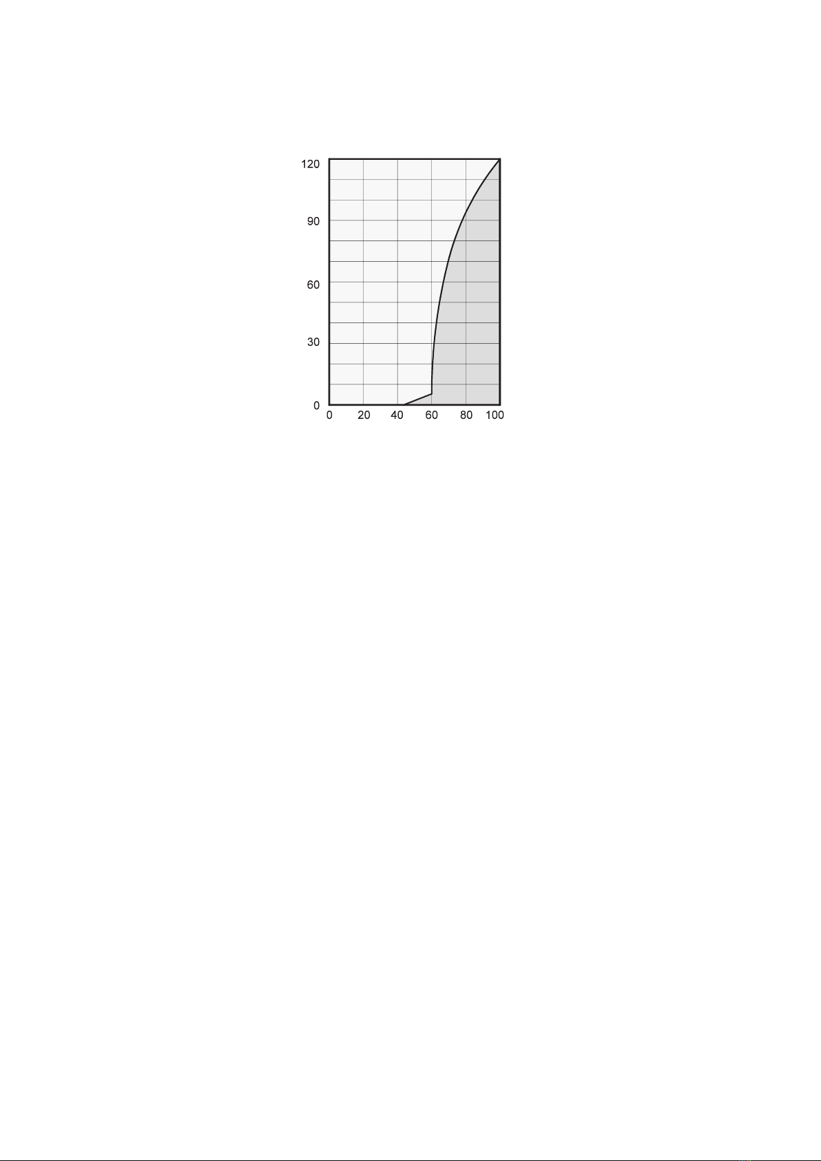
It is noticeable that the rate of
corrosion is insignificant below
50% relative humidity and can be
disregarded below 40% relative
humidity.
The rate of corrosion increases
noticeably from 60% relative
humidity. This humidity damage
limit applies also to numerous
other materials, e.g. powders,
packaging, wood or electronic
equipment.
Buildings can be dried out in
different ways:
1. Heating and air exchange:
The room air is heated to absorb
moisture to subsequently be
discharged to the atmosphere.
The total input energy is lost
with the discharged, moist air.
2. Dehumidification:
The moist air in an enclosed
room is continuously
dehumidified according to the
condensation principle.
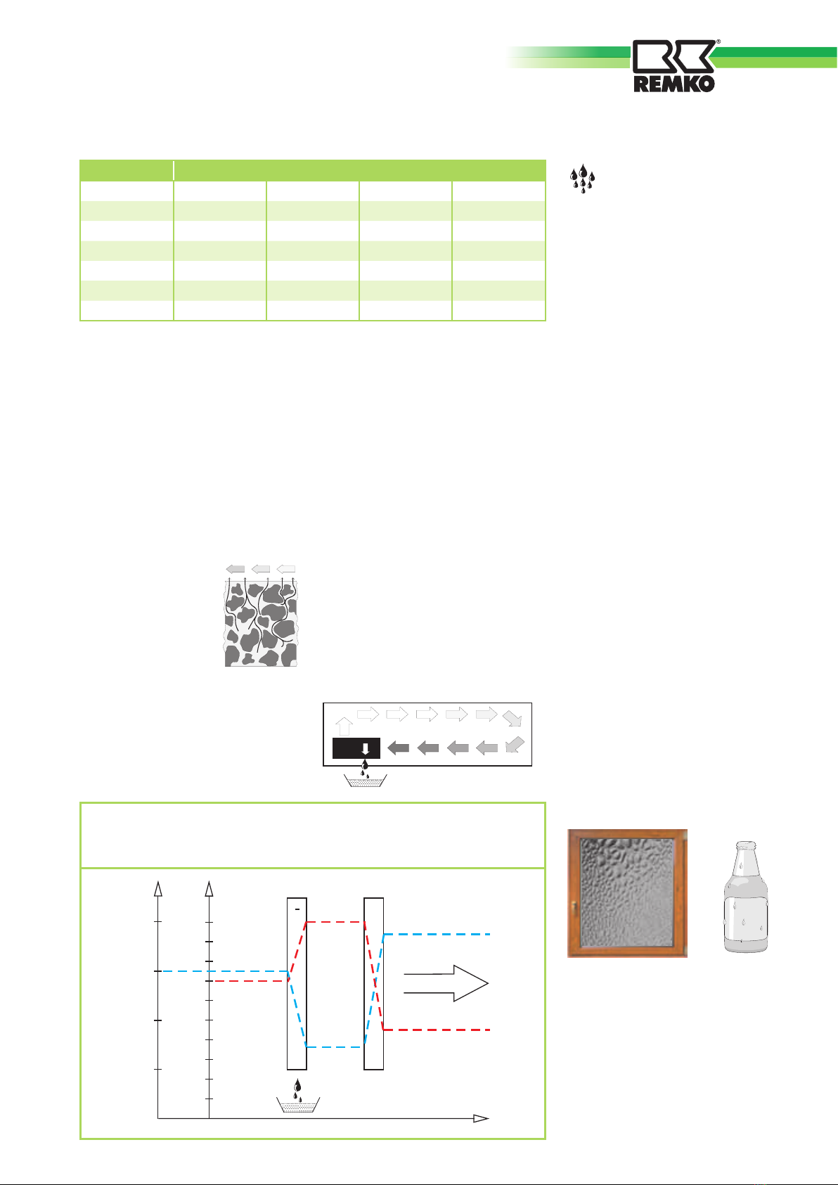
The interrelated processes
occurring during dehumidification
are based on physical laws.
These are illustrated here in
simplified form in order to explain
the principle of dehumidification.
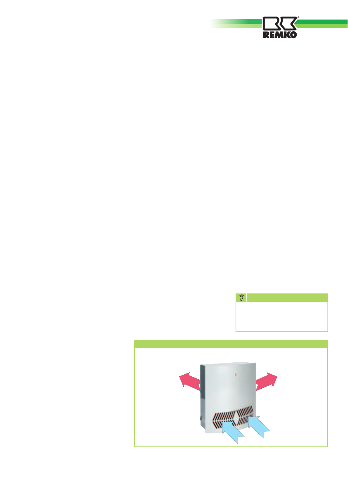
The use of REMKO
dehumidifiers
– No matter how well windows
and doors are insulated, damp
and moisture can penetrate
even through thick concrete
walls.
– The water volumes required
for binding concrete, mortar,
plaster, etc. are diffused out
initially after 1-2 months under
certain circumstances.
– Even moisture that has
penetrated masonry following
high water or flooding is
released very slowly.
– This applies similarly to e.g.
moisture contained in stored
materials.
The moisture (water vapour)
escaping from buildings or
materials is absorbed by the
ambient air. This increases their
moisture content and ultimately
results in corrosion, mould, rot,
peeling of paint coatings and other
unwanted moisture damage.
The diagram opposite shows an
example of the rate of corrosion,
e.g. for metal at different humidity
levels.
Dehumidification
In terms of energy consumption,
dehumidification has one decisive
advantage:
Energy expenditure is restricted
solely to the existing room volume.
The mechanical heat released
through the dehumidification
process is returned to the room.
With correct use, the dehumidifier
consumes only about 25% of the
energy required for the “heating
and ventilation” principle.
Relative humidity
Ambient air is a gas mixture
and always contains a certain
amount of water in the form of
water vapour. This water volume
is expressed in g per kg dry air
(absolute water content).
1m3air weighs about 1.2 kg at
20°C
Depending on the temperature,
each kg of air is only able to
absorb a certain amount of water
vapour. When this absorptive
capacity is reached, reference is
made to “saturated” air; this has a
relative humidity of 100%.
Relative humidity is therefore
understood to be the ratio
between the amount of water
vapour currently contained in
the air and the maximum water
vapour volume at the same
temperature.
The ability of air to absorb water
vapour increases with increasing
temperature. This means that
the maximum (= absolute) water
content increases with increasing
temperature.
Rate of corrosion
Rel. humidity in %
4
REMKO SLE 20

Condensation of water
vapour
Since the maximum water vapour
volume increases when the air is
heated, however the contained
water vapour volume remains the
same, this results in a reduction of
the relative humidity.
In contrast, when the air is
cooled, the capacity to absorb the
maximum water vapour volume
reduces, the water vapour volume
contained in the air remains the
same and the relative humidity
increases.
If the temperature falls further, the
capacity to absorb the maximum
water vapour volume is reduced
until it is equal to the contained
water vapour volume.
This temperature is called dew-
point temperature. When the air
is cooled below the dew-point
temperature, the contained water
vapour volume is larger than the
maximum possible water vapour
volume.
Water vapour is discharged.
This condenses to water. The air is
relieved of moisture.
Examples of condensing are misted
windows in winter or misting of a
cold drinks bottle.
The higher the relative humidity,
the higher the dew-point
temperature, which is easier to fall
below.
Building materials or structures
can absorb substantial amounts
of water, e.g. bricks 90-190 l/
m³, heavy concrete 140-190 l/m³,
lime-sand bricks 180-270 l/m³.
The drying out of moist materials,
e.g. masonry, takes place as
follows:
■
The contained
moisture moves
from the inside of
the material to its
surface
■
Evaporation takes place on the
surface = transition as water
vapour to the ambient air
Temp. Water vapour content in g/m3at a humidity of
°C 40% 60% 80% 100%
-5 1.3 1.9 2.6 3.3
+10 3.8 5.6 7.5 9.4
+15 5.1 7.7 10.2 12.8
+20 6.9 10.4 13.8 17.3
+25 9.2 13.8 18.4 23.0
+30 12.9 18.2 24.3 30.3
■
The air enriched with
water vapour continuously
circulates through the REMKO
dehumidifier. It is dehumidified
and leaves the unit at a slightly
higher temperature to absorb
water vapour from anew
■
In this way, the moisture
contained in the material is
gradually reduced
The material dries!
The produced condensate
is collected in the unit and
discharged.
Verdampfer Kondensator
°C
30
25
20
15
% r.F.
100
90
80
70
60
50
40
30
20
10
+
+
-
Lufttemperatur
Luftfeuchte
Verlauf
Luftrichtung
The air flow is cooled on its way through or via the evaporator to
below the dew point. The water vapour condenses and is collected
in a condensate trap and discharged.
Drying materials
5

Heat of condensation
The energy transferred from the
condenser to the air is composed
of:
1. Heat energy previously removed
in the evaporator.
2. Electrical motive energy.
3. Heat of condensation released
during liquefaction of the water
vapour.
For the change from a liquid to a
gaseous state, energy is necessary
This energy is called heat of
evaporation.
It does not cause any rise of
temperature, it is only necessary
for the change from a liquid to a
gaseous state.
Vice versa, energy is released
during the liquefaction of
gas, which is called heat of
condensation.
The amount of heat of evaporation
and condensation is the same.
For water, this is:
2250 kJ/kg (4.18 kJ = 1kcal)
This shows that a relatively large
amount of energy is released
through the condensation of water
vapour.
If the moisture to be condensed
is not introduced through evapo-
ration in the room itself, but from
outside, e.g. via ventilation, the
heat of condensation released in
the process contributes towards
room heating.
In drying processes, the heat ener-
gy is recirculated, which is consu-
med during evaporation and relea-
sed during condensation.
During dehumidification of
the supplied air, the amount of
heat energy produced is greater
than that expressed in a rise of
temperature.
The time necessary for drying
normally does not depend only
on the unit capacity, but is rather
determined by the rate at which
the material or parts of the build-
ing release their moisture.
Safety notices
The units were subjected to ex-
tensive material, functional and
quality inspections and tests prior
to delivery.
However, the units may constitute
a hazard if used by untrained per-
sonnel, improperly or not for the
intended purpose.
The following information must
be observed:
■ The units must not be installed
or operated in locations subject
to explosion hazards
■ The units must not be installed
and operated in atmospheres
containing oil, sulphur or salt
■ The units must not be exposed
to direct water jets
■ The air inlet and outlet must al-
ways be kept free
■ The air intake grilles must al-
ways be kept free of dirt and
loose objects
■ The units must not be covered
during operation
■ Never insert foreign objects into
the units
■ All electrical cables outside the
units must be protected against
damage (e.g. by animals, etc.)
ATTENTION
All work on the refrigeration
system and electrical
equipment must be referred to
an authorised specialist!
■ The units must only be installed
or mounted in the intended po-
sition (horizontal)
■ Free and frost protected
condensate drain must always
be ensured
■ The unit connections must al-
ways be established in compli-
ance with the applicable instal-
lation regulations
6
REMKO SLE 20

Description of the unit
The units are designed for
universal and problem-free
dehumidification.
They can be installed at numerous
locations due to their compact size.
The units operate according to
the condensation principle and
feature a hermetically sealed
refrigeration system, low noise and
maintenance circulating fan and
connecting cable with plug.
The fully automatic electronic
control with hot gas defrosting,
integrated hygrostat and
connections for local condensate
drain ensure trouble-free,
continuous operation.
The units are reliable and easy
to use and comply with the
fundamental health and safety
requirements of the pertinent EU
regulations.
The units are used wherever it
ist important to have dry rooms
and consequential damage (e.g.
through mould formation) is to be
avoided.
The units are also used for the
dehumidification of:
■
Private swimming pools
■
Wellness areas
■
Whirlpool areas
■
Sports studios
■
Store rooms/archives
■
Museums
Functional diagram of SLE 20 dehumidifier
Operation
The units can be switched on
and off with the operating switch
and the integrated hygrostat. In
dehumidification mode, the green
“dehumidification” pilot light at
the top of the front panel lights
up.
The recirculation fan sucks in the
humid room air via suction openes
integrated at the bottom of the
front panel.
This is transported via a filter,
evaporator and condenser.
Heat is extracted from the room air
on the cold evaporator and cooled
to below the dew point.
The water vapour contained in the
room air deposits as condensate or
frost on the evaporator tubes.
The cooled and dehumidified air is
reheated on the condenser (heat
exchanger) and blown back into
the room via the side outlet grilles
with a slight rise of temperature
of about 5°C above room
temperature.
The conditioned drier air
continuously mixes with the room
air.
Due to the constant circulation of
the room air through the unit, the
relative humidity in the room is
gradually reduced to the required
humidity (% relative humidity).
The hygrostat is set at the factory
to 50% relative humidity.
Depending on the room air
temperature and relative humidity
the condensed water drips
constantly or only during the
defrost phase into the condensate
trap and subsequently via the
integrated drain connection
into the condensate drain to be
provided locally.
Safety circuit:
If the temperature at the
condenser should exceed 55°C
(e.g. due to fan failure or clogged
suction filter), the unit stops
automatically to avoid being
overloaded.
The compressor restarts
automatically after 45 minutes.
NOTE
in normal operation, the
compressor always starts with
a delay of about 45 seconds.
Humid room air
Heated and
dehumidified air
Heated and
dehumidified air
7

Installation
For optimal and reliable unit
operation, the following
information must be observed in
any event:
■
The unit must be mounted or
installed in a suitable location
appropriate to the structural
conditions
■
The supplied wall bracket with
suitable fixing material (not
included) must be fixed securely
to the wall
■
The unit must be mounted or
installed horizontally to ensure
unhindered condensate drainage
■
The unit must be mounted or
installed so that the air is able
to be sucked in and blown out
unhindered
■
For optimal unit operation, the
minimum distances from the
unit to the ceiling and to the
floor must be observed
■
The unit should not be installed
in the immediate vicinity of
radiators or other heat sources
■
The room to be dehumidified
must be closed from the
ambient atmosphere
■
Open windows, doors, etc.
as well as frequent entering
and leaving the room must be
avoided as far as possible.
■
For optimal room air circulation
by the dehumidifier, the inlet
and outlet grilles must always
be kept free of dirt and other
obstacles
Condensate drain
The condensate drain is located at
the bottom of the unit.
The condensate drain must be
connected to the supplied drain
connection (not fitted).
A solid or flexible ½“ drain
connection can be connected.
■
The drain hose must always
be installed with a minimum
gradient of 2% to enable the
water to drain unhindered from
the drip tray
■
For an outlet through the
wall, specific preparations are
necessary for correct condensate
drainage prior to installation of
the unit, e.g. the drilling of holes
■
The position of the outlet
connection is shown in the
diagram below
Electrical connection
■
The units are
operated with
230V AC/50Hz
■
Electrical connection takes place
using a supplied mains cable
with safety plug
■
The unit must only be
connected to a socket-outlet
appropriate to the place of
installation and unit rating
ATTENTION
The unit connections must
always be established
in compliance with the
applicable installation
regulations.
ATTENTION
Careful and professional
installation or mounting must
be ensured.
ATTENTION
For securing the compressor
during transport, a cable tie
is attached at the back of the
unit.
This must be removed prior to
installation of the unit.
NOTE
A separate condensate
container with integrated
overflow protection is
available as an accessory.
252
62
Positioning the condensate drain
8
REMKO SLE 20

Additional condensate
container
Where it is not possible or difficult
to provide a natural condensate
drain, the unit can be provided
with an additional condensate
container.
The container is available as an
accessory.
The condensate container is
mounted directly below the unit,
see diagram below.
When the unit is used with
condensate container, the
dehumidifier switches off
automatically when the container
is full.
An LED on the front panel shows
a steady “red” light when the
container is full and needs to be
emptied.
The condensate container consists
of the following parts:
■
Condensate container housing
with electromagnetic switch
for the water stop and cable
connection to the printed board
■
Condensate collecting container
■
4 fixing screws
Unit with condensate container
Mounting the condensate
container
■
Mount the unit on the supplied
wall bracket
■
After removing 2 screws at the
top of the unit, lift up the front
panel and remove it from the
unit horizontally
■
Screw the condensate container
housing below the unit with 4
fixing screws
■
Route the unit connecting cable
through the diaphragm sleeve
at the bottom of the condensate
container housing
Access to control:
The electronic control is located in
a housing in the centre of the unit.
Access to the control takes place
by removing the 4 screws on the
sides of the housing.
■
Route the cable of the
electromagnetic switch through
the diaphragm sleeve at
the bottom of the unit and
connection to terminal 13 and
14 on the control board
■
Refit the cover of the control
and front panel of the unit
■
Place the condensate container
in the condensate container
housing.
Position the condensate
container so that the float points
towards the electromagnetic
switch
Prior to each commissioning or
depending on the local conditions,
the air inlet and outlet grilles must
be checked for clogging.
After switching on with the
operating switch, the unit operates
via an integrated hygrostat set to
50% relative humidity (standard
value for indoor and outdoor
swimming pools).
The unit does not start at room
air conditions below 50% relative
humidity.
If the relative humidity is above
50%, the unit automatically starts
the dehumidification process.
To change the hygrostat setting if
necessary, the front panel must be
removed.
The hygrostat is located below the
electronic control.
Turning the control knob clockwise
reduces the humidity, turning
it anticlockwise increases the
humidity.
An external hygrostat (accessory)
can be fitted if required.
For connection options, see
“Electrical connection diagram”.
In order to prevent compressor
damage, the units are provided
with reclosing protection, which
prevents immediate reconnection
of the compressor after
disconnection.
The compressor initially switches
on again after a delay of about 45
seconds!
Commissioning
9

Status display LED
The LED on the front panel lights
up:
green =unit dehumidifies
red = the water container
(accessory) is full and must
be emptied
Defrosting
At room temperatures below 20°C,
the evaporator will start to frost
after a short time.
When the evaporator sensor
registers a temperature on the
evaporator surface that is lower
than 5°C, the unit will continue
to operate for about a further 44
minutes in dehumidification mode.
After lapse of this time, the fan
stops and the evaporator surface
is defrosted by the injection of hot
gas.
When the evaporator sensor
registers a temperature above
5°C, the compressor is switched
on again and the dehumidification
mode is restarted.
■
Switch the operating switch to
the “0” position (off)
■
In case of extended periods
of non use, the units must be
disconnected from the supply
■
If provided, the condensate
container must be emptied and
rinsed with clear water.
Attention should be paid
to subsequent dripping
condensate!
Decommissioning
■
Observe regular care and
maintenance intervals
■
Depending on the particular
operating conditions, the
units should be tested by an
expert for reliable operation as
necessary, but at least once a
year
■
Keep the unit free of dust and
other deposits
■
If the unit should be fouled, it
must be cleaned carefully and
thoroughly with suitable agents
■
If the evaporator tubes should
be heavily fouled, these can be
cleaned carefully with soapy
water
■
Do not use a direct jet of water,
e.g. high pressure cleaner, etc.
■
Do not use caustic cleaning
agents or those containing
solvents
■
Only use suitable cleaning
agents to remove heavy fouling
Care and maintenance
All moving parts are provided
with low-maintenance permanent
lubrication. The refrigeration
system is a hermetically sealed
system and must only be
repaired by authorised specialised
companies.
NOTE
Regular care and maintenance
is a basic precondition for a
long useful life and trouble-
free operation of the unit.
Cleaning the suction filter
The suction filter should be
checked at regular intervals and
cleaned if necessary.
The filter is fixed in a holder
behind the intake grilles.
■
A lightly clogged filter can be
cleaned by carefully blowing out
or using suction
■
A heavily clogged filter can
be washed in a luke warm
(maximum 40°C) soapy
solution. Subsequently rinse
thoroughly with clear water and
allow to dry
■
It must be ensured that the
filter is completely dry and
undamaged prior to refitting
■
The units must only be operated
with the filter fitted
Cleaning the condensate
water collecting tray
To ensure that the produced
condensate water is able to drain
freely, the condensate collecting
tray and the outlet must be
cleaned at regular intervals.
NOTE
Heavily clogged filters must be
replaced with new ones.
Only original spare parts must
be used.
ATTENTION
Regularly check the inlet and
outlet grilles as well as filters
for clogging.
10
REMKO SLE 20

Troubleshooting
The units were manufactured using
the latest production methods
and tested repeatedly for perfect
function. If faults should still occur,
the unit must initially be checked
against the following list.
The unit does not start
■
Check setting of operating
switch
■
Check system connection and
local system fuse -230V/1~/50
Hz-
■
Check the mains plug and cable
for damage
■
Check the condensate container,
if provided for filling level and
correct seating
■
Check the integrated hygrostat.
Set the hygrostat to a lower
relative humidity (turn setting
knob fully clockwise)
If the unit does not start, the
integrated hygrostat must be
checked for faults.
Unit switches off
automatically – restarts after
45 minutes and switches off
again after a short time.
■
Does the fan operate when the
unit switches on again after 45
minutes?
■
Is the condenser surface possibly
fouled?
■
Is the suction filter clogged?
■
Is the ambient temperature
possibly above 30°C?
■
Are the intake and outlet grilles
free?
The unit operates, but no
condensate forms
■
Check room temperature
The operating range of the unit
is between 3°C and 30°C
■
Check the air humidity, min.
40% relative humidity is
necessary
■
Check the suction filter for
clogging and clean or replace if
necessary
■
Check the evaporator and
condenser for fouling and clean
if necessary
■
Check the evaporator for ice/
frost formation.
If this is the case, the
automatic defrost function and
temperature sensor must be
checked
The condensate container is
full – however the unit does
not switch off automatically
■
Check that the condensate
container is placed correctly
in the housing and the float is
correctly positioned pointing
towards the electromagnetic
switch
■
Check whether the float of the
water container moves freely or
is possibly damaged
ATTENTION
All work on the refrigeration
system and electrical
equipment must be referred to
an authorised specialist!
The red pilot light (fault)
lights up also when the
condensate container is
empty
■
Check whether the float of the
water container moves freely or
is possibly damaged
NOTE
If the unit does not function
perfectly despite checking, an
authorised specialist must be
contacted.
11

Electrical wiring diagram
Refrigeration circuit
5
FAN MAINSCOMPR.VALVE HOUR
COUNTER
M
1~
M
1~
COND.
NTC
EVAP.
NTC
HYGWATER
SW
TS1 TS2
S1
HYG Y1
M1M2
Electronic control board
Legend:
M1 = Compressor
M2 = Fan
TS1 = Condenser sensor
TS2 = Evaporator sensor
Y1 = Solenoid valve
Legend:
1. Compressor
2. Evaporator
3. Condenser
4. Capillary tube
5. Dry filter
6. Solenoid valve
7. Fan
7
3
4
62
1
We reserve the right to make changes to dimensions and the design in the interest of technical advances.
12
REMKO SLE 20

We reserve the right to make changes to dimensions and the design in the interest of technical advances.
Condensate container (accessories)
Spare parts list
No. Designation EDP No.
1 Housing 1109131
2 Holder for electromagnetic switch 1109132
3 Electromagnetic switch 1109133
4 Stop rail 1109134
5 Holder for condensate container 1109135
6 Housing bottom, complete 1109136
7 Float 1109139
8 Condensate container, complete 1109140
9 Front panel 1109142
2
1
3
4
5
6
8
9
7
Additional condensate
container
Where it is not possible or difficult
to provide a natural condensate
drain, the unit can be provided
with an additional condensate
container.
The condensate container is
mounted directly below the unit.
When the unit is used with
condensate container, the
dehumidifier automatically
switches off when the container is
full.
An LED on the front panel shows
a steady “red” light when the
container is full and needs to be
emptied.
NOTE
The condensate container has
a capacity of 6 litres.
Automatic switch off takes
place at a container level of 5
litres.
13

We reserve the right to make changes to dimensions and the design in the interest of technical advances.
Diagram of unit SLE 20
21
10
12
13
15
2
1
23
19
2425
26
3
9
28
6
8
4
14
27
22
16
17
14
REMKO SLE 20

Spare parts list
No. Designation EDP No.
1 Wall bracket 1109100
2 Housing, complete 1109101
3 Compressor, complete 1109102
4 Starting relay, complete 1109103
6 Operating switch 1109113
8 Fan motor 1109105
9 Fan blade 1109106
12 Control board 1109107
13 Diode board 1109108
14 Electronics cover 1109109
15 Solenoid valve, complete 1109110
16 Condenser NTC sensor 1109111
17 Evaporator NTC thermistor (metal) 1109112
19 Mains cable with plug 1109124
21 Condenser 1109114
22 Evaporator 1109121
23 Condensate tray, complete 1109122
24 Suction filter 1109127
25 Front panel 1109126
26 Hygrostat, complete 1109115
27 Dry filter 1109119
28 Capillary tube 1109120
When ordering spare parts, please always quote the EDP No. and serial number (see rating plate)! 15

Customer service and
warranty
A precondition for any warranty
claims is that the dealer or his
customer has completed and
returned the enclosed “Warranty
document” to REMKO GmbH &
CO. KG at the time of sale and
commissioning.
The units were repeatedly tested
for perfect functioning at the
factory. If problems should occur
which cannot be remedied by
troubleshooting by the operator,
your specialised dealer or contract
partner should be contacted.
Intended use
NOTE
Use for any other purpose
than that described in these
operating instructions is not
permitted.
Non-observance will invalidate
all liability and warranty
claims.
NOTE
Adjustments and maintenance
must be referred to authorised
specialists.
Important information on
recycling
The units are operated with
environmentally-friendly and
ozone neutral refrigerant R134A.
The refrigerant and oil mixture
contained in the unit must be
disposed of properly in accordance
with the statutory and locally
applicable regulations.
The units are designed and
equipped for dehumidification
purposes.
The manufacturer is not liable for
any damage attributed to failure
to observe the manufacturer‘s
instructions or applicable statutory
requirements or unauthorised
changes to the unit.
ATTENTION
Copyright
Reproduction of this document
in whole or part in any form
or use for purposes other
than that intended is strictly
forbidden without the prior
written permission of
REMKO GmbH & Co. KG
.
Environmental
protection and
recycling
Disposal of packaging
Think of the environment when
disposing of the packaging
material.
Our units are carefully packed for
transport and delivered in sturdy
cardboard packaging on a wooden
pallet, if necessary.
The packaging materials are
environmentally-friendly and can
be recycled.
By reusing packaging material,
you make a valuable contribution
towards waste reduction and the
conservation of raw materials.
Only dispose of packaging
material at the facilities provided.
Disposal of old unit
Our production is subject to
constant quality controls.
Only high-quality materials are
used, the majority of which are
recyclable.
Make your contribution towards
environmental protection by
disposing of your old unit in an
environmentally-friendly manner.
Only dispose of your old unit at
an authorised recycling facility or
collection point.
16
REMKO SLE 20

REMKO GmbH & Co. KG
ppa .................................
Signature (Technical Manager)
EC Declaration of Conformity
We herewith declare that the following dehumidifier complies with the pertinent requirements of the respective
EC directive in terms of its design and construction in the marketed version.
Important information:
This declaration will be invalidated if the unit is used, installed or maintained improperly, or if modifications are
made to the supplied unit without our prior permission.
Name of manufacturer : REMKO GmbH & Co. KG
Klima- und Wärmetechnik
Im Seelenkamp 12
D - 32791 Lage
Unit (machine) type : Permanently installed dehumidifier
Series : REMKO SLE 20
Series/Serial number : 730......
Applicable directives : MA - RL 89/392/EEC Machinery Directive [98/37/EC]
NS - RL 73/23/EEC Low Voltage Directive
EMC – RL 89/336/EEC EMC Directive
Reference standards : EN 292 - 1; EN 292 - 2; EN 294; EN 349;
EN 60204 - 1; EN 810; DIN 45635 - 1;
EN 60335 - 1; EN 60335 - 2 - 40;
EN 50081-1-EMC; EN 50082-1-EMC;
EN 55014-1; EN 55014-2; EN 55104;
EN 61000 - 3 - 2; EN 61000 - 3 - 3;
Position as at 30 March 2007
17

Maintenance report ✍
1. Date: ..............
..............................
Signature
2. Date: ..............
..............................
Signature
3. Date: ..............
..............................
Signature
4. Date: ..............
..............................
Signature
5. Date: ..............
..............................
Signature
6. Date: ..............
..............................
Signature
7. Date: ..............
..............................
Signature
8. Date: ..............
..............................
Signature
9. Date: ..............
..............................
Signature
10. Date: ............
..............................
Signature
11. Date: ............
..............................
Signature
12. Date: ............
..............................
Signature
13. Date: ............
..............................
Signature
14. Date: ............
..............................
Signature
15. Date: ............
..............................
Signature
16. Date: ............
..............................
Signature
17. Date: ............
..............................
Signature
18. Date: ............
..............................
Signature
19. Date: ............
..............................
Signature
20. Date: ............
..............................
Signature
Remarks: .....................................................................................................................................................
.............................................................................................................................................................................
.............................................................................................................................................................................
.............................................................................................................................................................................
.............................................................................................................................................................................
Unit type: .................................. Serial number: ...................................
1 2 3 4 5 6 7 8 9 10 11 12 13 14 15 16 17 18 19 20
Unit cleaned – outside –
Unit cleaned – inside –
Condenser cleaned
Evaporator cleaned
Fan function checked
Unit checked for damage
Protective devices checked
All fixing screws checked
Electrical safety checked
Test run
The unit must only be serviced by authorised specialists in compliance with the statutory requirements.
18
REMKO SLE 20

Series SLE 20
Daily dehumidification capacity at 30°C and 80%
relative humidity Litre/day 10.5
Daily dehumidification capacity at 30°C and 60%
relative humidity Litre/day 7.5
Operating temperature range °C 3-30
Humidity operating range % relative
humidity 40-100
Air capacity m3/h 220
Refrigerant R134a
Refrigerant quantity g 190
Power supply V/Hz 230/1~/50
Max. nominal current consumption A 2.1
Max. power input kW 0.39
Sound pressure level LpA 1m 1) dB (A) 46
Depth mm 240
Width mm 535
Height mm 600
Weight kg 28
EDP No. 615200
Technical data
We reserve the right to make changes to dimensions and the design in the interest of technical advances.
1) Noise measurement DIN 45635 - 13 - Category 3
Unit dimensions
All dimensions in mm
600
535
240
580
485
160
833
600
160
485
815
580
240
535
SLE 20 Standard SLE 20 with condensate container
19

REMKO EUROPE-WIDE
.... and somewhere near you!
Take advantage of our experience and consulting services
REMKO GmbH & Co. KG
Klima- und Wärmetechnik
Im Seelenkamp 12 D-32791 Lage
Postfach 1827 ·D-32777 Lage
Telephone +49 5232 606-0
Fax +49 5232 606-260
E-mail [email protected]
Internet www.remko.de
Consulting
Through intensive training, we ensure
that the expert knowledge of our
consultants is always up-to-date. This
has given us the reputation of being
more than just a good, reliable supplier:
REMKO, a partner who helps solve
problems.
Sales
REMKO not only has an extensive sales
network in Germany and abroad, but also
unusually highly qualified sales experts.
REMKO field representatives are more than
just salesmen: they must also be customer
consultants in air conditioning and heating
technology.
Customer service
Our units operate precisely and
reliably. If a fault should occur, REMKO
Customer Service is there to help you.
Our extensive network of experienced
specialised retailers guarantees our
customers a fast and reliable service at
all times.
Subject to technical changes, information supplied without liability!
Table of contents
Other REMKO Dehumidifier manuals

REMKO
REMKO SLE 65 User manual

REMKO
REMKO ETF 100 User manual

REMKO
REMKO SLN 40 User manual

REMKO
REMKO ETF 240 User manual

REMKO
REMKO ETF 550 User manual

REMKO
REMKO ETF 320 Eco User manual

REMKO
REMKO ASF 100 User manual

REMKO
REMKO LTE 50 Eco User manual

REMKO
REMKO ETF Eco Series User manual

REMKO
REMKO ETF 220 User manual

REMKO
REMKO SLE 45 User manual

REMKO
REMKO ETF-S Series User manual

REMKO
REMKO ETF Series User manual

REMKO
REMKO ETF 320 User manual

REMKO
REMKO ETF 360 User manual

REMKO
REMKO LTE 50 User manual

REMKO
REMKO AMT 45-E User manual

REMKO
REMKO AMT 60-E User manual

REMKO
REMKO LTE Eco Series User manual

REMKO
REMKO HITLINE TK Series User manual