REMKO ASF 100 User manual

Edition GB – T12
REMKO ASF 100
Portable dehumidifier
with adsorption rotor
Operation · Technology · Spare parts


3
Table of contents
Made by REMKO
These operating instructions must be read carefully before
commissioning/using the unit!
These instructions are part of the unit and must always be
kept near to the site of installation or on the unit.
Subject to changes; errors and typographical errors excepted!
Unit description 4
Installation 5
Safety information 6
Commissioning 6
Decommissioning 9
Unit transport 9
Care and maintenance 10
Troubleshooting 11
Intended use 12
Customer service and warranty 12
Environmental protection and recycling 12
Maintenance report 13
Electrical wiring diagram 14
Capacity graph 14
Technical data 15

4
REMKO ASF 100
Unit description
Operation
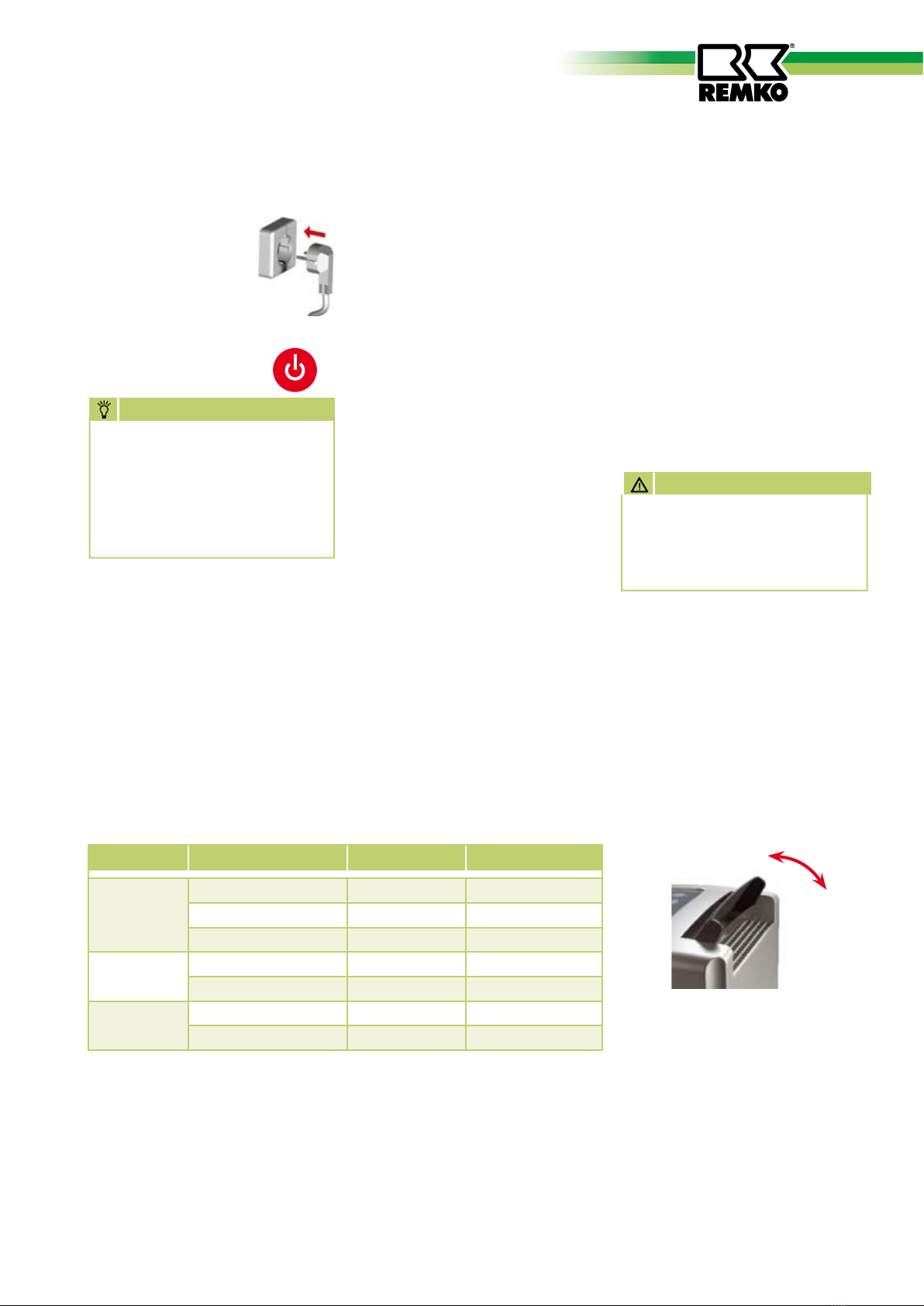
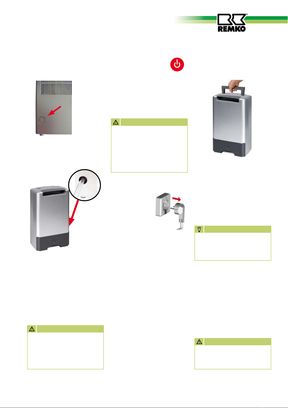
The units can be switched on and
off with the ON/OFF button.
The LED of the last selected mode
lights up in the control panel.
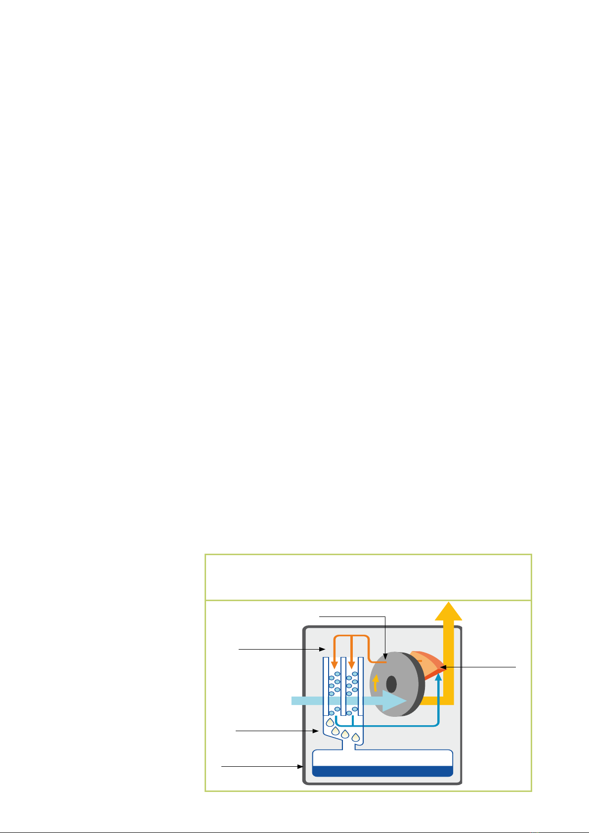
The recirculation fan draws in the
humid room air via the inlet grille
with filter, condenser and follow-
ing adsorption rotor.
In the internal regeneration circuit,
the air flows across a heating ele-
ment, dries the adsorption rotor
and passes the humid air through
the condenser.
On the cooler condenser, heat is
removed from the room air and
cooled to below dew-point. The
water vapour contained in the
room air deposits as condensate.
Depending on the room air tem-
perature and relative humidity,
the condensed water constantly
drips through the integrated drain
connection into the condensate
container located below.
The conditioned drier air continu-
ously mixes with the room air. Due
to the constant circulation of the
room air through the unit, the
relative humidity in the room is
gradually reduced to the required
humidity (45% relative humidity).
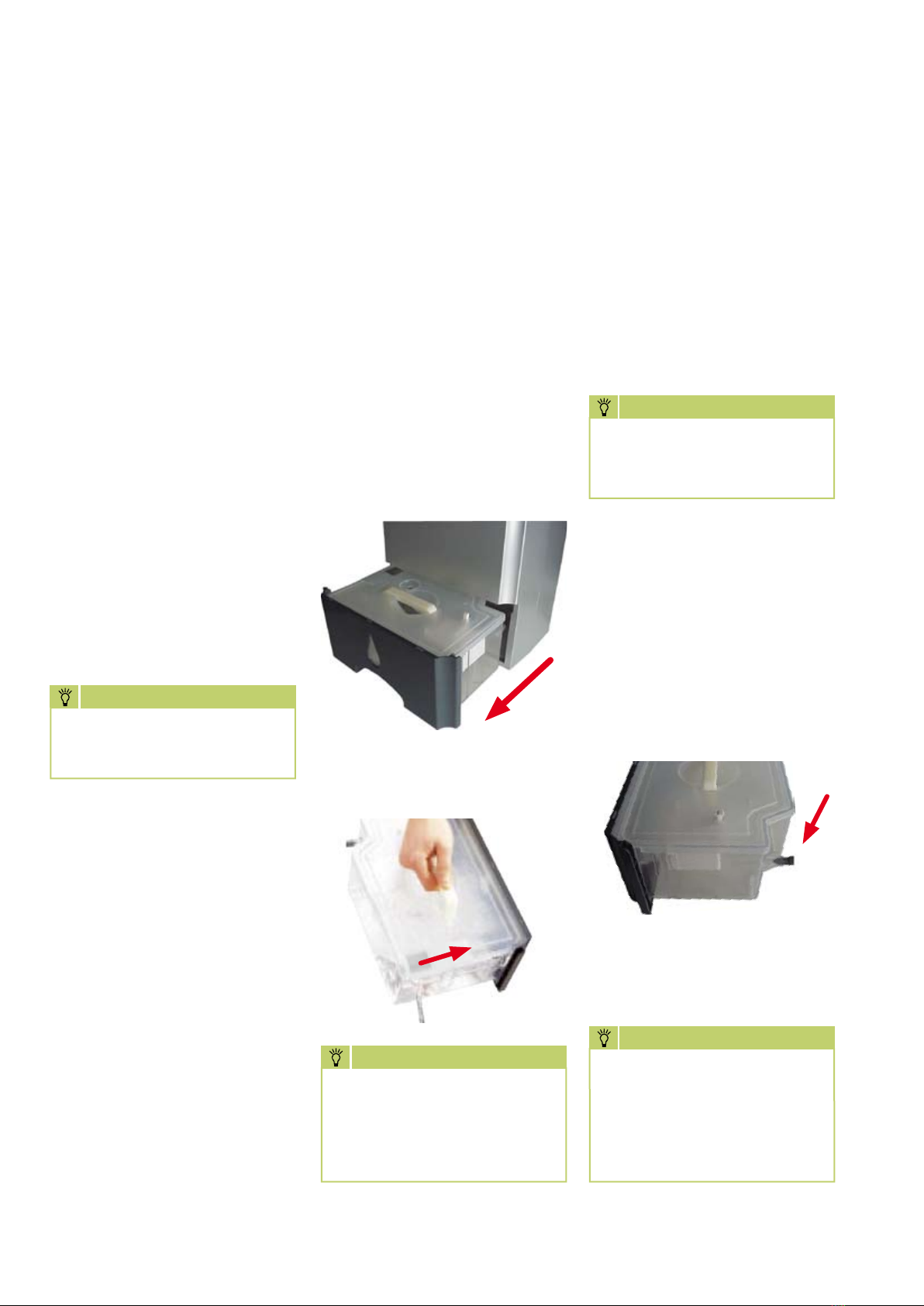
A float switch in the condensate
container interrupts dehumidifica-
tion via a microswitch when the
container is full. The units switch
off with an audible signal
(5x) and the „FULL TANK“ indica-
tor light illuminates on the control
panel. This does not extinguish
until the emptied condensate con-
tainer is refitted. The units return
to the previously selected mode.
In an unsupervised continuous
mode with external condensate
connection, the produced
condensate is continuously drained
via a hose connection on the
condensate container.
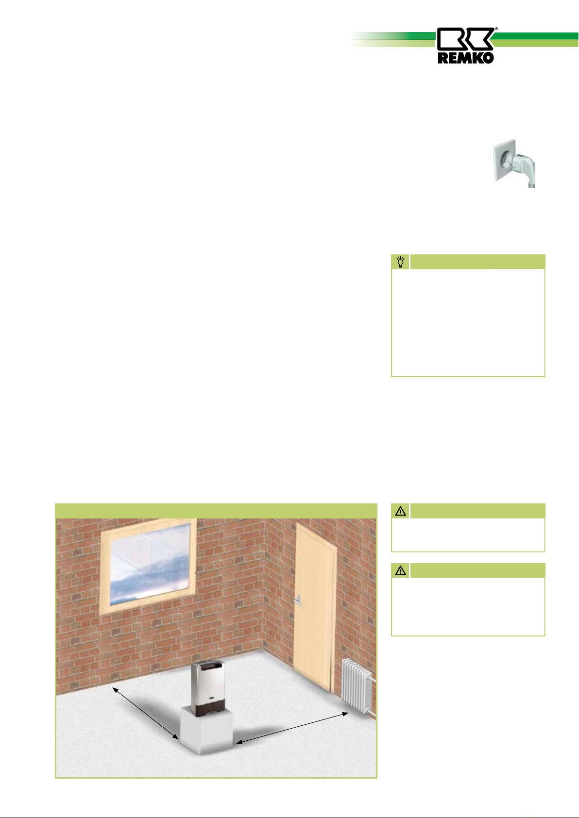
The units are designed for
universal and problem-free
dehumidification.
Owing to their compact size, they
are easy to transport and install.
The units operate according to the
adsorption principle and are pro-
vided with ioniser, low noise and
maintenance recirculation fans as
well as a power cord with plug.
The fully automatic control, the
condensate container with inte-
grated overflow protection and the
drain connection for direct con-
densate discharge ensure trouble-
free operation.
The units comply with the
fundamental safety and health
requirements of the pertinent EU
directives.
The units are reliable and easy to
operate.
The units are used wherever
dehumidification is necessary and
consequential damage (e.g. due to
mould formation) is to be avoided.
The units are also suitable for
drying and dehumidification of:
■
Living rooms, bedrooms,
shower or cellar rooms, lofts
■
Utility rooms, weekend homes,
caravans
■
Museums, archives, laboratories
■
Wellness areas, washrooms and
changing rooms, etc.
■
Garages, store rooms
The air flow is cooled on its way through or via the condenser to
below the dew point. The water vapour condenses and is collected
in a condensate trap and discharged.
saturated air
condenser
condensate container
humid
room air
regenerative
heating element
adsorption rotor dehumidified
room air

5
Electrical connection
■
The units operate
on 230V
AC/50 Hz
■
Electrical connection takes place
using the fitted power cord
with safety plug.
■
Cables must only be extended
depending on the cable length,
unit rating and taking local use
into account.
Installation
For optimal and reliable unit
operation, the following
information must be observed in
any event:
■
The units must be installed
stable and horizontal to
ensure unhindered condensate
drainage.
■
The units should be placed
in the centre of the room if
possible to ensure optimal air
circulation.
■
It must be ensured that the
room air can be sucked in and
blown out freely.
■
A minimum distance of 40 cm
to walls and 60 cm above the
unit must be maintained in any
event.
■
The units must not be installed
in the immediate vicinity of
radiators or other heat sources.
■
Optimal room air circulation is
achieved when the units are
installed about 1 m above the
ground.
■
The room to be dried or dehu-
midified must always be closed
from the ambient atmosphere.
■
Open windows, doors, etc., as
well as frequently entering and
leaving the room should be
avoided as far as possible.
■
The units must not be used in
dusty, chlorine or ammonia-
containing atmospheres.
■
The unit output depends
solely on the room conditions,
room temperature, relative
humidity and observance of the
installation instructions.
ATTENTION
All extension cables must only
be used uncoiled.
wall distance
minimum 0.4 m
maintain distance to radiators or
other heat sources.
keep windows and doors closed!
Diagram showing installation of the REMKO dehumidifier
NOTE
For installation of the units
in damp areas such as utility
rooms, shower rooms or
similar, the units must be
protected with a residual-
current-operated circuit-
breaker complying with the
requirements.
ATTENTION
The unit must not be discon-
nected from the supply before
the after-running time of 2
minutes has elapsed.

6
REMKO ASF 100
Prior to each commissioning
or as required, the air inlet and
outlet grilles must be checked for
clogging.
Important information
prior to commissioning
■
All electrical extension cables
must have a sufficient cross-
section and only be used fully
uncoiled.
■
Do not pull at the power cord.
■
After switching on, the units
operate fully automatically until
switched off controlled by the
timer or float switch of the full
condensate container.
■
The condensate container must
be fitted correctly.
The unit will not function if the
condensate container is not fit-
ted correctly!
■
For safety reasons, the units are
fitted with a tilt switch which
prevents operation of a unit
that has toppled over or is lying
vertically.
The unit can only be restarted
when it is placed upright!
■
In an unsupervised continuous
mode with external condensate
connection, the produced con-
densate is continuously drained
via a hose connection on the
condensate container.
Commissioning
Control panel
The control panel contains control
buttons and indicator lights.
➊ON / OFF
The unit is switched on and off
with this button.
Note switch off delay of about
2 minutes.
➋MODE
This button is used for selecting
the 3 modes “POWERFUL”,
“SILENT” and “NORMAL”.
➌TIMER
This button is used to activate
the switch off timer for 2, 4 or 8
hours.
➍AUTO SWING
This button is used to activate
the automatic swing mode of
the air directing flap.
➎IONIC
This button is used to switch
on the ioniser for enriching
the room air with negatively
charged ions.
➏ ”FULL TANK” indicator light
This indicator light shows when
the condensate container is full
and requires emptying. When
the unit is switched off via the
float switch, the unit generates
5 audible signals.
Safety information
The units were subjected to ex-
tensive material, functional and
quality inspections and tests prior
to delivery.
However, the units may constitute
a hazard if used by untrained per-
sonnel, improperly or not for the
intended purpose.
The following information must
be observed:
■ The units must not be installed
and operated in hazardous
areas.
■ The units must not be installed
and operated in oil, sulphur,
chlorine or salt containing
atmospheres.
■ The units must be installed up-
right and stable.
■ The units must not be exposed
to direct water jets.
■ The air openings must always be
kept free.
■ The air inlet grilles must always
be kept free of dirt and loose
objects.
■ The units must not be covered
during operation.
■ Never insert foreign objects into
the units.
■ The units must not be transport-
ed during operation.
■ The units must only be trans-
ported upright.
■ The condensate containers must
be emptied prior to each change
of location.
➊
➋➌
➍
➎
➏
NOTE
Clogged grilles and filters must
immediately be cleaned or
replaced.

7
POWERFUL
This is the most powerful mode.
relative humidity 45 – 55%
- max. dehumidification capacity
- max. fan setting
relative humidity below 45%
- dehumidification off
- max. fan setting
„AUTO SWING“ button
This button is used to activate
the oscillating function of the air
directing flap.
Pressing the button again stops the
flap at the respective position. The
most favourable air flow position
can be selected in this way.
The swing function serves to
improve the air distribution within
the room.
The following information must
also be observed:
■
Free air flow must be ensured.
This ensures optimal unit
operation!
■
It must be ensured that sensi-
tive items, e.g. indoor plants
are not placed directly in the air
flow.
After 12 hours operation at
maximum power, the control
automatically selects the min.
power setting.
ATTENTION
Unit commissioning
1. Connect the units
to a properly fused
power socket.
2. Press the ON/OFF
button on the control
panel.
3. The air directing flap at the top
of the unit opens fully. The unit
is the „NORMAL“ mode and
the ioniser and timer are not
activated.
4. Select the required mode with
the „MODE“ button.
NOTE
As long as the unit is not
disconnected from the power
supply, the last selected mode
(MODE, IONIC, and AUTO
SWING) is active when the
unit is switched on.
NORMAL
This is the comfort mode.
The unit regulates according to
time (12 hours) or on reaching
the preset humidity, the dehu-
midification capacity and fan
setting.
relative humidity above 55%
- max. dehumidification
capacity
- moderate fan setting
relative humidity 45 – 55%
- min. dehumidification
capacity
- min. fan setting
relative humidity below 45%
- dehumidification off
- min. fan setting
SILENT
This is the most silent mode.
Optimal for night operation.
Relative humidity above 45%
- min. dehumidification
capacity
- min. fan setting
relative humidity below 45%
- dehumidification off
- min. fan setting
Mode Power consumption Fan setting Relative humidity
NORMAL
2. Setting / 560W medium above 55%
1. Setting / 340W min. 45 - 55%
— min. below 45%
SILENT 1. Setting / 340W min. above 45%
— min. below 45%
POWERFUL 2. Setting / 560W max. 45 - 55%
— max. below 45%
Electronic program sequence
After 12 hours continuous operation at max. power setting, the control
automatically selects the min. power setting.
If the relative humidity subsequently falls below 45%, the dehumidifica-
tion function is switched off.
The fan continues to run at minimum speed for moisture measurement. If
the relative humidity subsequently rises above a value of 45% again, the
minimum dehumidification setting is activated. Return to the maximum
power setting can only take place via the ON/OFF button manually.

8
REMKO ASF 100
3. Carefully place the emptied con-
densate container with closed
slider in the unit.
The “Tank full” indicator light
extinguishes and the unit contin-
ues to operate fully automatically.
Continuous operation with exter-
nal condensate connection
The condensate containers are
provided with a special connection
at the back.
After removing the sealing plug,
a suitable drainage hose can be
connected.
Connection external
diameter = 11mm
Empty condensate container
The installed condensate container
must be emptied from time to
time.
When the condensate container is
full, dehumidification is interrupted
with the generation of an audible
signal.
The “Tank full” indicator light
shows that the unit has switched
off.
1. Carefully pull out the full tank.
2. Open the slider in the corner of
the container and pour out the
water into a drain.
NOTE
After each emptying, the
condensate container including
float switch must be checked
for possible damage, fouling,
etc.
IONISER
The unit has an ioniser genera-
tor for the generation of negative
ions.
A high concentration of negative
ions occurs, e.g. in mountainous
regions, at waterfalls and in forests
and the air we inhale is „pure“.
Only a small ion concentration is
present in rooms.
Here, the ion generator is able to
enrich the oxygen molecule ions
in the circulated air and provide a
pleasant atmosphere.
Also, suspended and dust particles
in the air are bound so that natural
air purification can take place.
As a result of ionisation, the dust is
able to deposit on smooth surfaces
and removed manually.
This function is active in all modes
after selection.
TIMER
This button is used to program a
decremental switch off timer. The
timer can be set to 2, 4 or 8 hours
by pressing the button repeatedly.
Pressing the button again switches
off the timer.
NOTE
The housing and filter clean-
ing intervals reduce when
using the ioniser.
NOTE
The unit will only start with
a correctly fitted condensate
container.
NOTE
Also when using an external
condensate hose, the conden-
sate container initially fills up
to the level of the connection
before condensate discharges
from the hose.

9
1. Remove the cover [F] from
the rear wall of the unit with a
suitable tool.
2. A suitable drainage hose of
sufficient length can be routed
to the outside through the free
opening.
The condensate must preferably
be discharged to a lower located
outlet in unsupervised continuous
duty.
When using an external container
(tub, bucket, etc.) the unit must be
placed in a raised position.
Decommissioning
ATTENTION
It must be ensured that the
drainage house is routed to the
drain with a gradient to ensure
that the condensate is able to
flow out freely!
Unit transport
F
Switch off the unit with
the ON/OFF button on
the control panel.
The mode LED extinguishes. The
unit initially switches off com-
pletely after lapse of a preset after-
running time of 2 minutes.
If the units are not
used for extended
periods of time,
they must be
disconnected from
the power supply.
The condensate container must be
emptied completely and dried with
a clean cloth.
Pay attention to subsequently
dripping condensate!
Prior to possible storage, the units
must be cleaned thoroughly and
dried.
For storage purposes, the units
should be covered with plastic
sheeting and stored in an upright
position in a protected and dry
location.
The units must only be stored
in upright in a suitable location
protected from dust and direct
sunlight.
ATTENTION
Never disconnect the unit
from the power supply during
operation by pulling out the
mains plug. This can damage
the control electronics.
Dam-
age of this kind is not covered
by the warranty
.
F
The units are provided with a
handle for easy and convenient
transport.
■
The unit must be switched off
and the plug removed from the
power socket each time before
the unit is moved to a different
location.
■
The condensate container must
be emptied completely.
■
As long as residual moisture is
still present in the unit or water
is present in the condensate
container, the units must only be
transported upright.
NOTE
Attention must be paid to
dripping condensate.
Condensate can still drip after
switching off the unit.
ATTENTION
The power cord must never
be used for pulling or fixing
purposes.

10
REMKO ASF 100
4. Clean the air inlet grille with
warm water or a vacuum
cleaner.
5. A heavily clogged grille with
filter can be washed in a warm
soap solution (maximum 40°C).
Subsequently rinse thoroughly
with clear water and allow to
dry!
6. It must be ensured that the grille
with filter is completely dry and
undamaged prior to refitting.
NOTE
Heavily fouled or damaged air
inlet grilles must be replaced
with new ones.
Only original spare parts must
be used.
Filter cleaning
The unit is provided with an inte-
grated air filter to prevent damage.
To prevent a reduction in
performance and faults, the air
inlet grille with filter must be
checked as required, however at
least once a week and cleaned if
necessary.
1. Switch off the unit with the
button. Note the after-running
time!
2. Disconnect the plug from the
power socket.
3. Pull the air inlet grille out of the
unit at the recessed grip [G].
ATTENTION
The units must not be used
without air inlet grille fitted!
G
All moving parts are provided
with low-maintenance permanent
lubrication.
■
Observe regular care and main-
tenance intervals.
■
Depending on the particular
operating conditions, the units
should be tested by an expert
for reliable operation as neces-
sary, however at least once a
year.
■
Only clean the units dry or with
a moist cloth
Do not use a jet of water!
■
Do not use caustic cleaning
agents or those containing
solvents.
■
Only use suitable cleaning
agents to remove heavy
fouling.
■
Regularly check the air inlet and
outlet grilles for fouling.
Clean or replace if necessary!
Care and maintenance
NOTE
Regular care and maintenance
is a basic precondition for a
long useful life and trouble-
free operation of the unit.
ATTENTION
Before carrying out all work
on the units, the mains plug
must be disconnected from the
power socket.

11
Cleaning internal components
For cleaning the interior of the unit
and to gain access to the electri-
cal components, it is necessary to
open the unit housing.
■
Clean the components either by
blowing out, suction, inlet grille
or with a soft brush. Do not use
a jet of water!
■
Carefully clean the internal
surfaces of the unit, condensate
trap with hose connection, fan
and fan housing.
■
Check all unit components for
possible damage and repair if
necessary.
■
Carefully refit all previously
removed components in the
reverse order.
NOTE
Only authorised specialists
may carry out adjustments and
maintenance.
Troubleshooting
The units were manufactured us-
ing the latest production methods
and tested repeatedly for perfect
function.
If faults should still occur, the unit
must be checked against the fol-
lowing list.
The unit does not start:
■
Check unit installation (tilt
switch)
The unit will only operate in an
upright position!
■
Check the supply connection
and system fuse
230V/1~/50
Hz
on-site
■
Check the mains plug and
power cord for damage
■
Check the condensate container
for level and correct seating
The “FULL TANK” indicator
light must not light up!
■
Check the microswitch of the
condensate container
■
Check for free air flow
Overheating
!
■
Check the miniature fuse on the
control pcb
The unit operates, but with
no condensate formation:
■
Check the room temperature
The operating range of the unit
is between 1°C and 40°C
■
Humidity has not reached
the fixed value (45% relative
humidity)
■
Check the air inlet and outlet
grilles for fouling
Clean or replace if necessary!
■
Have the exchanger surface of
the absorption rotor checked
for fouling.
This work makes it necessary
to open the unit and must
be carried out only by an
authorised specialist!
The unit is loud or
condensate discharges:
■
Check that the unit is standing
on a level and firm surface.
■
Check that the unit is standing
upright and stable.
■
Have the condensate trap or
connection checked for dirt
deposits.
This work makes it necessary
to open the unit and must
be carried out only by an
authorised specialist!
NOTE
Only authorised specialists
may carry out adjustments and
maintenance.
NOTE
Particular care must be taken
when cleaning the adsorption
rotor as the surface must not
be subjected to any mechani-
cal load.
ATTENTION
After carrying out all work on
the units, an electrical safety
test must be carried out in ac-
cordance with VDE 0701.

12
REMKO ASF 100
Customer service and
warranty
A precondition for any war-
ranty claims is that the dealer or
his customer has completed and
returned the enclosed “Warranty
document” to REMKO GmbH &
Co. KG.
The units were repeatedly tested
for perfect functioning at the
factory.
If malfunctions should occur
that cannot be remedied by
troubleshooting, your specialised
dealer or contract partner should
be contacted.
Intended use
Disposal of packaging
Think of the environment when
disposing of the packaging
material.
Our units are carefully packed for
transport and delivered in sturdy
cardboard packaging on a wooden
pallet if necessary.
The packaging materials are
environmentally-friendly and can
be recycled.
By reusing packaging material,
you make a valuable contribution
towards waste reduction and the
conservation of raw materials.
Only dispose of packaging mate-
rial at the facilities provided.
The units are designed and
equipped for drying and dehumidi-
fication purposes.
The units must not be used for any
other purposes.
The units must only be operated
by suitably trained persons who
are familiar with the operation of
the unit.
The manufacturer is not liable for
any damage attributed to failure
to observe the manufacturer‘s
instructions or applicable statu-
tory requirements or unauthorised
changes to the unit.
NOTE
Any other operation other than
that described in these operat-
ing instructions is not permit-
ted.
Non-observance will result in
all liability being disclaimed
and render warranty entitle-
ments null and void.
NOTE
Only authorised specialists
may carry out adjustments and
maintenance.
Environmental
protection and
recycling
Disposal of old unit
This unit must not be disposed of
together with normal household
waste but must be must be taken
to a special collection point for
recycling electrical and electronic
equipment.
The materials can be reused ac-
cording to their marking.
Reusing or recycling materials and
old appliances makes an important
contribution towards protecting
the environment.
To find out about your nearest dis-
posal facilities, contact your local
authorities.
ATTENTION
Copyright
Any copying of this docu-
ment in whole or part or use
for purposes other than the
intended is strictly forbid-
den without the prior written
permission of
REMKO GmbH
& Co. KG
.

13
Maintenance report
The unit must only be serviced by authorised specialists in compliance with the statutory requirements.
✍
1. Date: ..............
..............................
Signature
2. Date: ..............
..............................
Signature
3. Date: ..............
..............................
Signature
4. Date: ..............
..............................
Signature
5. Date: ..............
..............................
Signature
6. Date: ..............
..............................
Signature
7. Date: ..............
..............................
Signature
8. Date: ..............
..............................
Signature
9. Date: ..............
..............................
Signature
10. Date: ............
..............................
Signature
11. Date: ............
..............................
Signature
12. Date: ............
..............................
Signature
13. Date: ............
..............................
Signature
14. Date: ............
..............................
Signature
15. Date: ............
..............................
Signature
16. Date: ............
..............................
Signature
17. Date: ............
..............................
Signature
18. Date: ............
..............................
Signature
19. Date: ............
..............................
Signature
20. Date: ............
..............................
Signature
Remarks: .....................................................................................................................................................
.............................................................................................................................................................................
.............................................................................................................................................................................
Type of unit: .................................. Serial number: ...................................
1 2 3 4 5 6 7 8 9 10 11 12 13 14 15 16 17 18 19 20
Unit cleaned – externally -
Unit cleaned – internally -
Fan blade cleaned
Fan housing cleaned
Condenser cleaned
Adsorption rotor cleaned
Fan function tested
Air inlet grille with filter cleaned
Unit checked for damage
Protective devices checked
All fixing screws checked
Checked for electrical safety
Test run

14
REMKO ASF 100
We reserve the right to make changes to dimensions and design in the interest of technical advances.
Electrical wiring diagram
L
N
F , 3 15A
230 V/1~/50Hz
Thermal fuse
Front
Heating element
Thermal fuse
Rear
Heating element
Heating element
Transformer
Output
Transformer
Input
Control panel
Thermostat
Heating element
Fan
Circulation air
Fan
Regeneration
circuit
Adsorption
rotor
Ioniser
Microswitch
Humidity sensor
Fin motor
510 15 20 25 30
2
4
6
8
10
12
Room temperature °C
Dehumidification capacity litre/day
80 % r.H.
60 % r.H
Capacity graph
Miniature fuse

15
Technical Data
1) Dependent upon the respective mode.
Series ASF 100
Operating temperature °C 1 bis 40
Operating humidity % r. H. 45 - 100
Max. dehumidification output l/day 8.7
at 20°C/70% relative humidity l/day 8.0
at 15°C/60% relative humidity l/day 7.0
Max. air volume flow m3/h 150
Condensate container capacity Litre 3.0
Power supply V 230/1~
Frequency Hz 50
Max. rated power consumption A 2.6
Max. power input kW 0.60
Sound pressure level LpA 1m 1) dB (A) 34 - 48
Depth mm 300
Width mm 195
Height mm 500
Weight kg 6.5

Subject to technical changes, errors and omissions excepted!
REMKO EUROPE-WIDE
... and somewhere near you!
Take advantage of our experience and consulting services
REMKO GmbH & Co. KG
Klima- und Wärmetechnik
Im Seelenkamp 12 D-32791 Lage
P.O. Box 1827 ·D-32777 Lage
Telephone +49 5232 606-0
Fax +49 5232 606-260
E-mail [email protected]
Internet www.remko.de
Consulting
Through intensive training, we en-
sure that the expert knowledge of our
consultants is always up-to-date. This
has given us the reputation of being
more than just a good, reliable sup-
plier: REMKO, a partner that helps solve
problems.
Sales
REMKO not only has an extensive sales
network in Germany and abroad, but
also unusually highly qualified sales
experts.
REMKO field representatives are more
than just salesmen. They must also be
customer consultants in air conditioning
and heating technology.
Customer service
Our units operate precisely and reliably.
If a fault should occur, REMKO Custom-
er Service is there to help you. Our ex-
tensive network of experienced specialist
retailers guarantees our customers a fast
and reliable service at all times.
Table of contents
Other REMKO Dehumidifier manuals

REMKO
REMKO ETF 360 User manual

REMKO
REMKO LTE 50 Eco User manual

REMKO
REMKO ETF-S Series User manual

REMKO
REMKO ETF 550 User manual

REMKO
REMKO ETF 100 User manual

REMKO
REMKO SLN 40 User manual

REMKO
REMKO ETF 360 User manual

REMKO
REMKO ETF Eco Series User manual

REMKO
REMKO AMT 45-E User manual

REMKO
REMKO SLE 65 User manual

REMKO
REMKO HITLINE TK Series User manual

REMKO
REMKO SLE Series User manual

REMKO
REMKO LTE Eco Series User manual

REMKO
REMKO AMT 60-E User manual

REMKO
REMKO LTE 120 User manual

REMKO
REMKO LTE 50 User manual

REMKO
REMKO ETF 320 User manual

REMKO
REMKO ETF 320 Eco User manual

REMKO
REMKO SLE 20 User manual

REMKO
REMKO ETF Series User manual