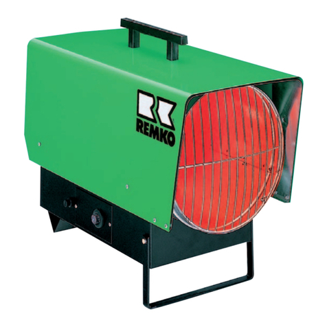
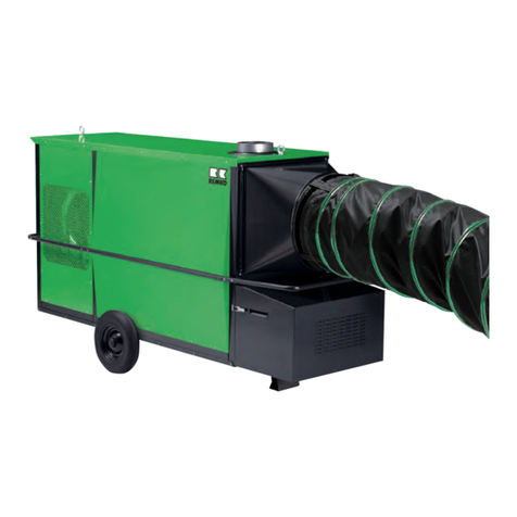
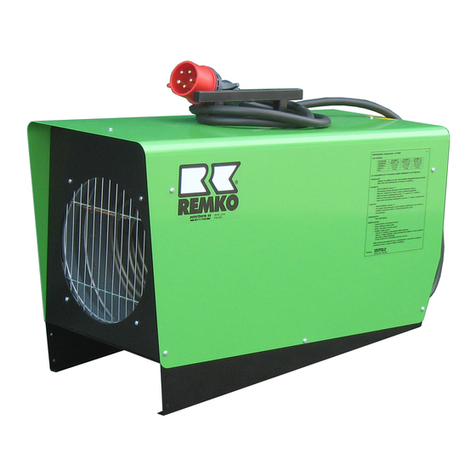
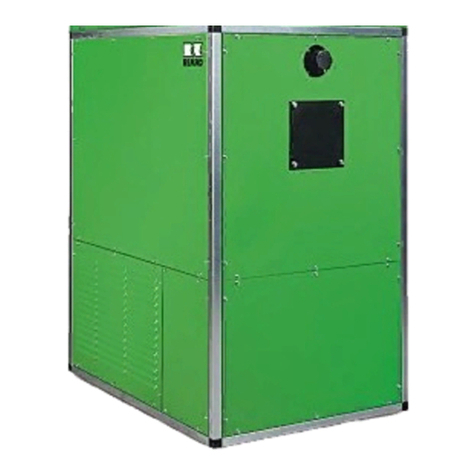
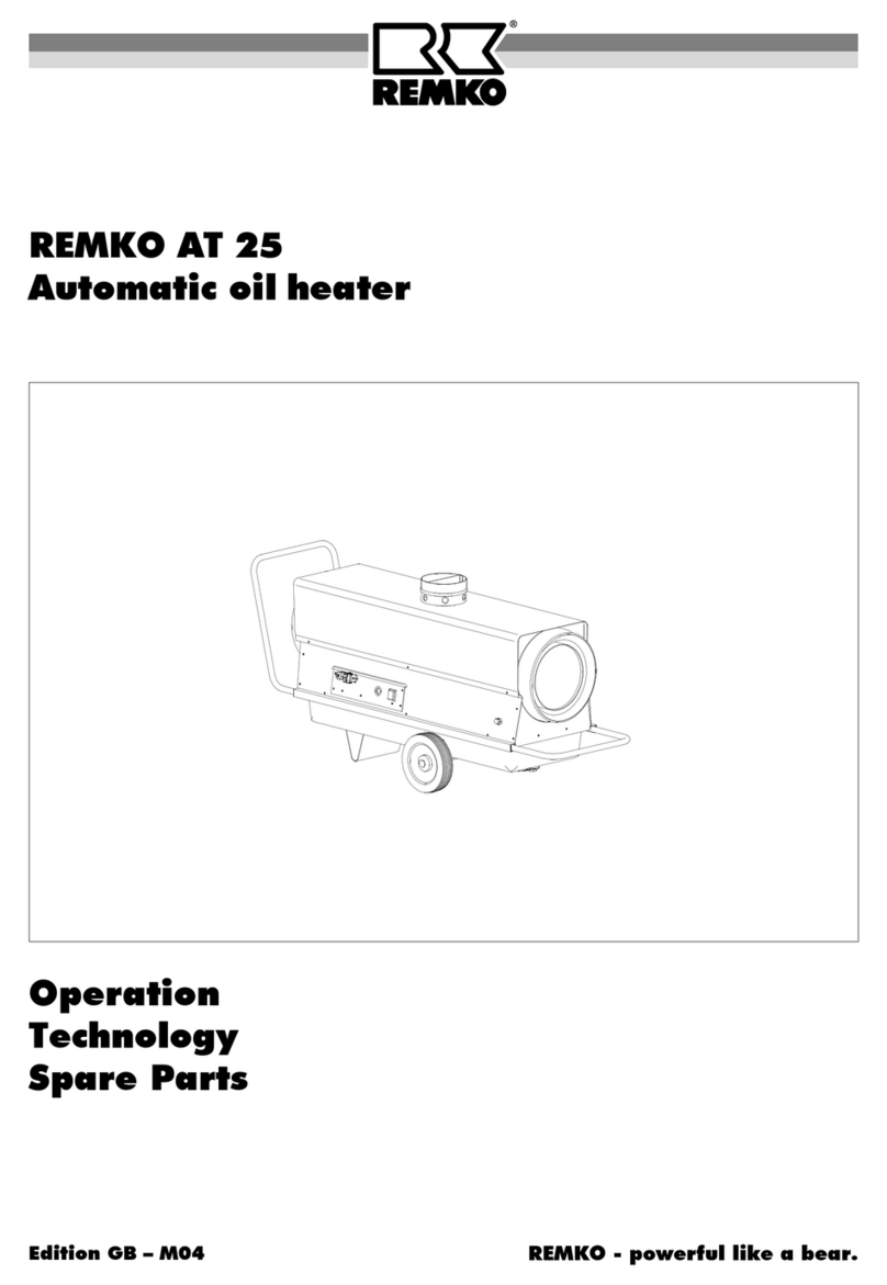
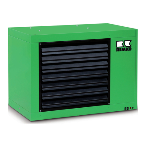
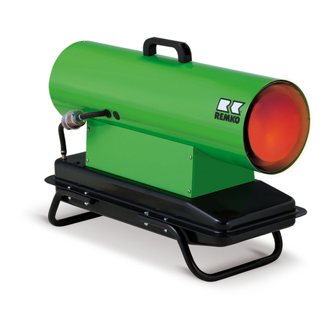
REMKO HTL 150 FB User manual

REMKO – powerful like a bear.
REMKO HTL 150 FB - HTL 250 FB
Mobile oil-fired heating centers
Edition D – R02
Operation
Technology
Spare Parts


3
Contents Page
Safety Instructions 4
Description of Device 4
Safety Mechanisms 5
Unit Assembly 6
Prior to Operation 8
Initial Operation 8
Shutting Down the Unit 9
Troubleshooting 9
Maintenance and Service 10
Contents Page
Customer Service and Guarantee 11
Forced-Air Oil Burner 12
Exploded View 14
Spare Part List 15
Wiring Diagram HTL 150 FB 16
Wiring Diagram HTL 200/250 FB 17
Wiring Diagram HTL-FB 18
Technical Data 18
Maintenance Log 19
Read these instructions carefully before setting up/operating the unit!
Our guarantee becomes null and void if the unit is used, set up
or maintained improperly, or if modifications are made to the supplied unit
without our prior consent.
Subject to alterations!
Mobile oil-fired heating centers
REMKO HTL 150 FB
REMKO HTL 200 FB
REMKO HTL 250 FB
Operating instructions
*Always keep these operating instructions near or on the unit! *

4
Safety Instructions
Make sure to observe relevant local building and fire
protection codes and abide by professional associa-
tion regulations when the unit is in operation.
◊ The unit may only be operated by persons who have
received training in its operation.
◊ The units must be installed and operated in such a
way that people are not exposed to hazards such as
exhaust, warm air or radiant heat and fires cannot
occur.
◊ The units may only be installed and operated in
closed rooms if the units have an adequate air sup-
ply for combustion.
◊ Portable fuel containers may only be set up if the
technical regulations for combustible liquids “TRBF
210 and 280” are observed.
◊ If the units do not have an exhaust outlet, they may
only be operated in well-ventilated rooms.
People are not permitted to remain in the room
where the units are set up for longer periods of time.
Warning signs must be placed at the entrances.
◊ The unit may only be set up on a non-flammable
surface.
◊ The unit may not be set up or operated in surround-
ings susceptible to fire or explosions.
◊ A safe distance off 1.5 m must be maintained
around the unit; a distance of 3 m must be main-
tained from its exhaust opening, even for non-
flammable objects.
◊ The air suction grille must always be kept free of dirt
and loose objects.
◊ Never insert foreign objects into the unit.
◊ Do not expose the unit to a direct stream of water.
◊ All of the units’ electric cables are to be protected
from damage, e.g. caused by animals, etc.
◊ Before performing any work on the unit, make sure
to unplug the unit from the power supply.
◊ Safety mechanisms may not be bypassed or
blocked.
◊ Use only prototype-tested WLE-type oil burners in
accordance with DIN 4787 and DIN-EN 267
Description of Device
The units are fired directly with heating oil or diesel.
They are designed for fully-automatic, universal and
reliable use.
The units are equipped at the factory with a large-
volume fuel preheater as well as a heating oil filter
protected from weather conditions. They are operated
with a separate forced-air oil burner and are suitable
for outdoor operation.
The units are equipped both with a high-performance
axial fan that requires little maintenance and inte-
grated switching and regulating units. They also have
an optical display which shows the individual operat-
ing functions.
The units have a sturdy framework design on robust
transport runners.
To ensure that the units can be operated over a pe-
riod of many years, particularly outdoors, the frame-
work and the lining plates are made of rust-proof
stainless-steel. In addition, all of the construction parts
inside the unit are also made of non-corrosive materials.
The compact design of the units makes them easy
and affordable to assemble quickly and guarantees
that they are easy to service.
The unit meets the basic safety and health require-
ments found in the relevant EU regulations and is
easy to operate.
*
The units are not designed for permanent fixed in-
stallation.
Locations for unit operation
The units are direct-fired, warm air heaters that supply in-
stantaneous heat. They are only used for commercial pur-
poses.
The units are used in the industrial area when portable
units are required to heat or regulate the temperature
of, for example:
– Warehouses
– Exhibition spaces
– Trade shows
– Large tents
– Temporary structures for warehousing
– Large construction sites
There are generally no restrictions as to where they can
be used for temporarily heating buildings due to their
weatherproof design.
Functionality
If the unit is switched to heating mode, the forced-air oil
burner switches on automatically. The green “burner“
operating light is illuminated on the control panel for
monitoring purposes. If heating mode is controlled by a
room thermostat, the forced-air oil burner starts only
when heat is required.
Proper Use
These devices have been designed and equipped exclu-
sively to be used for heating and ventilation for industrial
and commercial purposes.
The manufacturer is not liable for any damage resulting
from non-adherence to manufacturer specifications, le-
gal requirements or any modifications to the units.

5
Safety Mechanisms
Three-speed combination regulator in accordance
with DIN 3440
The unit has 3 functions:
◊ Fan regulator (TR)
◊ Temperature monitor (TW)
◊ Safety temperature limiter (STB)
Fan regulator (TR)
The temperature control thermostat switches the circu-
lation fan on and off. The activation point is set by
means of the adjustment lever.
Target value approx. 35 °C.
Temperature monitor for the burner (TW)
The temperature monitor limits the temperature of the
units and the air being blown out via the burner in heat-
ing mode. The activation point is set using the adjust-
ment screw on the target value spindle.
Target value approx. 85°C.
Safety temperature limiter (STB)
The STB controls the temperature monitor. There is a
button that, when pressed, prevents the burner from the
restarting. The reset button on the control box must be
pressed
The activation point is fixed in accordance with DIN
3440.
Information about the safety mechanisms
The sensors of the safety mechanisms are self-
monitoring and can work at cold temperatures of down
to -20 °C. At temperatures below 20 °C, they switch off
and when the temperature rises, they switch back on
again.
When the sensor or capillary tube is damaged, or when
an excess temperature of approximately 220°C is
reached, the liquid contained in the thermostat is emp-
tied and the safety mechanism switches the unit off.
The temperature control thermostat is no longer oper-
able and must be replaced.
If the three-speed combination regulator needs to be re-
placed, only use the original REMKO-spare part ref. no.
1102562.
Make sure to observe the following:
◊ Make absolutely sure that the units are carefully in-
stalled and assembled.
◊ Do not bend the capillary tubes close to solder
points.
◊ When installing the capillary tubes, be careful not to
damage or bend them too sharply.
◊ The sensors may only be mounted at the attachment
points created for this purpose at the factory.
◊ The sensors must always be kept free of dirt and
dust.
The combustion chamber with heat-exchanger is
heated up until the temperature monitor switches on
(target temperature of 80 to 85 °C). The temperature
regulator (target temperature 35 to 40 °C) automatically
switches the air supply fan on beforehand. The green
“fan“ operating light is illuminated on the control panel
for monitoring purposes. Warm air is blown out.
When the room thermostat is in operation, the process
above is automatically repeated depending on the
amount of heat required
.
After the device is switched off with the operating switch
or the room thermostat, the air supply fan runs for a cer-
tain amount of time to cool the combustion chamber with
heat-exchanger and then switches off. This process can
be repeated several times.
Monitoring Unit Operation
All functions of the device are her carried out fully auto-
matically and monitored for safety by the three-speed
combination regulator and the automatic burner relay
(part of the forced-air oil burner).
If the flame burns irregularly or goes out, the unit is
switched off by the automatic burner relay. The control
lamp on the control panel and the red malfunction lamp
“Burner” light up.
The unit may only be restarted after the automatic
burner relay has been manually released by pressing
the “Burner” reset button on the control box.
The temperature control thermostat (TR) regulates op-
eration of the fan. The temperature monitor (TW) limits
the temperature of the air blown out of the unit in heat-
ing mode via the forced-air oil burner.
The safety temperature limiter (STB) interrupts opera-
tion of the unit or burner when extreme overheating oc-
curs or if the TW stops working or is defective. The red
malfunction light “Overheating” is illuminated on the
control panel.
The STB is released by pressing the “Overheating” but-
ton on the control panel. The STB can only be manually
released after the unit has cooled.
The fan motor is monitored by a thermal overcurrent re-
lay. If the capacity of the motor is overloaded, operation
is interrupted by the relay and the red malfunction light
“Fan” is illuminated on the control panel.
All electrical components are also protected by safety
mechanisms. They can only be reset once the control
box has been opened. Prior to opening the control box,
the unit must be unplugged from the power supply.
Prior to resetting the unit, the causes of the malfunction
must be identified.
*
Before releasing the safety temperature limiter
(STB), the possible causes of the malfunction
must be identified.

6
Unit Assembly
When setting up the units, the relevant regional building
and fire protection codes of the respective region must
be observed.
When selecting an indoor or outdoor location to set up
the units, the settings must be adjusted with respect to:
◊ Fire protection and operating hazards
◊ Maintenance of adequate safety zones
◊ Function
Room heating, free-standing or canal system, ex-
cessive or low pressure in the setup room.
◊ General requirements
Heating needs, room temperature, rated air output,
air distribution, need for circulation or outside air,
space needs, etc.
◊ Exhaust system
◊ Assembly, repair and servicing options
◊ Indoor setup
Ratio of room volume to rated air capacity especially
for naturally ventilated rooms.
Setup
◊ The units must be placed firmly on a suitable, non-
flammable surface outside of traffic zones, for exam-
ple, away from cranes.
◊ If the surface is soft, appropriate substructures must
be set up such as scantlings below the transport,
runners.
◊ When doing work on the units, make sure that the
units are current-free and set up horizontally.
◊ The units must be set up and operated in such a
way that people are not exposed to exhaust or radi-
ant heat and fires cannot occur.
◊ The units must be set up in such a way that they do
not cause any hazards or unreasonable annoy-
ances.
Tremors, vibrations or noise.
◊ The units must be set up and installed in such a way
that they are easily accessible for repair and mainte-
nance work.
◊ Operating elements which can result in dangerous
operating conditions when used improperly must be
protected from unauthorised .
◊ The units may not be set up or operated in rooms or
areas susceptible to fire or explosions.
◊ The unit may only be set up and operated in rooms if
there is an adequate supply of air for combustion
and the exhaust is expelled via exhaust flues.
◊ A natural air supply sufficient for combustion exists
when, for example,
- the room content in m³ is equivalent to at least 10
times the rated heat output in kW of all heating
units in operation in the room and natural air venti-
lation is supplied through windows and doors.
◊ Good natural ventilation exists when, for example,
- the room content in m³ equals 30 times the rated
heat output of all units in operation in the room
and natural ventilation is supplied through doors
and windows .
Expulsion of exhaust
When the units are operated outside or in open rooms
you do not need an exhaust system.
However, to safely expel exhaust, an exhaust pipe 1 m
long with a rain cover (accessory) should be attached to
protect people and keep rain from getting into the com-
bustion chamber.
For indoor setup (closed rooms) an appropriate exhaust
system that meets the valid regulations is required.
Important information about longer exhaust lines
To prevent damage to the combustion chamber caused
by moisture build-up (condensation) for longer exhaust
lines, make sure that the exhaust gas pipe has a prop-
erly installed condensation trap.
Fuel supply
The customer must ensure that certified safety tanks
provide an adequate fuel supply.
◊ You must observe any additional regulations of the
respective regional building codes as well as the
technical regulations for combustible liquids “TRBF
210 and 280".
◊ Particularly for heating oil lines, make sure that the
cross-section of the lines corresponds to the suction
height, the total line resistance and increased vis-
cosity at lower temperatures. If necessary, it is pos-
sible to connect an oil transport device.
◊ The suction line must be equipped with a valve at
the end of the hose in the tank.
◊ To ensure that operation in heating mode is as
smooth as possible, there must be an adequate
quantity of heating oil available that can flow even at
low outdoor temperatures. Appropriate measures,
for example, the use of a tank heater, must be un-
dertaken to ensure that boil can flow freely.
*
Paraffin can accumulate at temperatures starting
at approximately 5 °C!

7
Schematic diagram (example)
Warm air
Circulation
Circulation mode
A pipe adapter (accessory) on the suction side is
necessary for pure circulation mode.
◊ Air lines her hold their shape must be placed on the
intake side.
Do not use unstable lines.
◊ When setting up the unit outside, a folded spiral-
seam pipe or similar device should be used for
circulation.
Fresh air mode
Air is taken in at the back of the units (factory made).
Schematic diagram (example)
Warm air
Fresh air
Electrical connection
◊ The units are operated with 400/3~N/50.
◊ The unit must be connected to the power source at a
special terminal equipped with a switch to protect
against faulty currents in accordance with VDE 0100
§ 55.
◊ The design of the connection cable depends on the
unit’s electrical capacity and the length of the cable
and takes into account the local conditions.
◊ Extension cords may only be used if they are com-
pletely unrolled or rolled up.
Warm air distribution
The units are equipped with a high-performance axial
fan that requires little maintenance. This fan has been
designed, depending on the requirements, to direct the
warm air efficiently.
It is preferable to distribute air by means of pipes or
special hot air and plastic hoses. The possible lengths
of these lines depend on the air-side resistance of the
warm air ducting.
Make sure to observe the following when using warm
air hoses:
◊ Use only warm air hoses (accessories) approved by
our company.
◊ The inner overlappings of the seams of the warm air
hoses must point in the direction of the air.
◊ Make sure that the hoses and/or pipes are securely
attached to the unit’s air outlet connection.
◊ To prevent heat from building up, the pipes and
hoses may not have sharp kinks and bends.
◊ We recommend using folded spiral-seam pipes.
◊ Use warm air or plastic hoses only for straight air
lines if possible.
◊ Plastic hoses may not be twisted.
◊ When heating closed rooms via warm air lines, no
counter pressure may not build up.
◊ If the suction temperatures or resistance on the unit
outlet increases, the forced-air oil burner can be
switched off in heating mode temporarily by the tem-
perature monitor (TW).
Once the temperature has fallen, the burner
switches are again automatically.
◊ If the intervals are too short, the length of the warm
air line should be checked.
*
Avoid starting the forced-air oil burner in frequent
cycles (under 5 min.).
*
If blockages cause the unit to heat up, heating op-
eration is permanently interrupted by the STB!
Operating modes
The units can be used in the fresh air and circulation
modes.

8
7. Check whether the green control lights for phases
and control phase are lit up on the control box.
8. Open all shut-off mechanisms of the fuel supply.
9. Set the operating switch on the control box to
“I” (heating).
10.Remember that the forced-air oil burner does not
switch on immediately when heat is required, the air
supply fan only switches on once the target tem-
perature has been reached.
11.Check whether the operating lights for the burner
and fan are lit up on the control box.
12.Close the door.
13.Lock the door to protect the unit from unauthorised
operation.
Operating mode
The unit operates fully automatically according to the
pre-selected room temperature.
If the suction temperatures or resistance on the unit
output increased, the burner can be temporarily
switched off during heating mode by the temperature
monitor (TW).
After the temperature has fallen, the burner automati-
cally starts again. You should avoid starting the burner
frequently during unit operation.
If the temperature increases too much on the air outlet,
the STB interrupts heating mode permanently!
Prior to Operation
Prior to initial operation, check the unit for any visual
defects on the control and safety mechanisms, make
sure that it has been installed correctly and that it has
been properly connected to the power supply.
The exhaust values of the forced-air oil burner must be
checked and adjusted by authorised personnel in line
with the respective on-site conditions.
After installation of the complete air distribution system,
the following checks should be performed by trained
personnel to ensure that the fan always runs properly!
Measuring the rated power and power consumption
1. For correct measurement, attach all pipes to the out-
let and intake sides and open any outlet grilles.
2. Check the available power supply.
3. Make sure that the rated current (amperes) specified
on the motor type plate is not be exceeded.
Setting the thermal overcurrent relay
1. Measure each phase separately to eliminate meas-
urement errors.
2. Set the thermal overcurrent relay according to the
following calculation:
Multiply the rated current of the drive motor by 0.58
and adjust the thermal overcurrent relay to the cal-
culated value.
3. Check the function of the overcurrent relay and its
set value by simulating a missing phase.
By switching off a fuse, etc.
4. Keep in mind that if the relay is functioning and set
properly, it will start after approximately 30 seconds.
Caution, important information about the overcur-
rent relay!
The thermal overcurrent relay may only be operated
when set to “Manual Reset”. The relay may not be
switched back on again automatically after cooling.
Power consumption too high
If the motor is consuming too much power despite hav-
ing a proper electrical connection and adequate power
supply, the thermal overcurrent relay may not be set
higher or bypassed under any circumstances.
◊ Take appropriate measures to fix the problem, e.g.
by checking or adjusting the diameter of the intake
and outlet on the air side.
*
If the overcurrent relay is operated in “Automatic
Reset” mode, it is possible that the motor will be
damaged. We assume no liability for the guaran-
tee!
Initial Operation
A person who has been adequately trained in how to
operate the unit is to be given responsibility for operat-
ing and monitoring it.
Starting the unit
1. Open the door on the back of the unit.
2. Ensure that the operating switch on the control box
is set to “0” (off) .
3. Place the room thermostat in a suitable location.
The thermostat sensor may not be in the warm air
current nor attached directly to a cool surface.
4. Connect the room thermostat to the thermostat
socket on the control box.
5. Set the room temperature you want on the room
thermostat.
The setting must be higher than the current room
temperature.
6. Connect the unit to a properly installed and fused
power socket.
*
Extension cords may only be used if they are com-
pletely unrolled or rolled up .
*
The maximum air suction temperature may not ex-
ceed 30 °C.

9
Circulation mode
In this operating mode, only the air supply fan runs and
the unit can be used to circulate air.
Thermostat regulation and heating operation are not
possible.
1. Set the operating switch on the control box to
“II” (= ventilate).
The burner doesn’t start
1. Open the shut-off valve on the oil filter.
2. Check the oil filter for dirt.
3. Make sure that the fuel tank has an adequate
amount of fuel.
4. Check the heating oil for paraffin accumulation.
Paraffin can build up at temperatures as low as 5 °C!
5. Check the oil lines for damage.
There is a danger that there are air bubbles in the
lines.
6. Check whether the safety temperature limiter (STB)
was triggered.
This could be caused by the following:
- The unit was not able to cool down because the
power supply was interrupted.
- The air outlet temperature is too high because air
is not being directed properly.
- Air cannot flow freely in and out.
7. Prior to a STB reset, you must analyse the causes
and fix this problem.
8. Check that the temperature monitor (TW) is function-
ing properly using appropriate means.
9. Check the sensors and the capillary pipes of the
three-speed combination regulator for damage and
dirt.
See “Safety Mechanisms” chapter.
10. Check whether the “Burner” malfunction light is lit up.
If so, release the burner by pressing the “Burner Re-
set” button on the control box.
The burner tries to start.
Shutting Down the Unit
1. Set the operating switch on the control box to
“0” (off).
2. Shut off the fuel supply.
Important information about the cool-down phase
of the unit.
The air supply fan continues to run to cool the combus-
tion chamber and the heat-exchanger and switches off
at a later time.
The fan can be run several times until the unit is finally
switched off.
*
Never interrupt the power supply (except in emer-
gencies) before the cool-down phase is complete.
We assume no liability for damage to the unit by
overheating.
Troubleshooting
The unit doesn’t start
1. Check the power connection and the power fuses.
2. Set the operating switch to “I”.
3. Make sure the plug of the room thermostat is posi-
tioned properly.
4. Check the setting of the room thermostat.
The set temperature must be higher than the current
room temperature.
5. Check the fuses F1 and F6 in the control box.
6. Check whether the safety temperature limiter was
triggered. In this case, release it by pressing the
“Overheating Reset” button on the control box.
7. Prior to a STB reset, you must analyse the causes
and fix this problem.
8. Set the operating switch to “II” (ventilating).
If the air supply fan now starts, look for the problem
with the burner.
The air supply fan does not start
1. Check whether the “Fan” malfunction light is lit up. If
so, to press the “Fan Reset” button on the control
box.
2. Check the fuses F1 to F3 in the control box.
3. Check the control fuse F6 in the control box.
4. Check the electrical cord to the fan for damage.
5. Check that the temperature regulator (TR) is func-
tioning properly with appropriate means.
*
Repair and maintenance work on the burner or
electrical installations may only be performed by
authorised personnel for safety reasons.
Important information about releasing the burner
◊ If the burner switches off again due to a malfunction
during the start phase, it may only be reset after
waiting 5 min.
◊ Resetting the burner again is strictly prohibited.
There is a danger of explosion.

10
Removing the combustion chamber
To clean the unit, it is necessary to completely remove
the combustion chamber with heat-exchanger.
1. Set the operating switch on the control box to
“0” (off)
2. Unplug the power supply.
3. Remove the fixing screws of the
rosette 1.
4. Pull the rosette from the exhaust gas connection 2.
5. Remove the exhaust gas connection from the com-
bustion chamber and pull it up and out.
6. Remove the lining plate on the side 3and the insula-
tion 4.
7. Open the front lock cover 5.
8. Remove the attachments
grew 6and pull the burner
out.
9. Remove the fixing screws 7
on the burner flange and re-
move the burner flange.
Do not damage the flange
seal 8 when doing so
1 2
3
4
5
Maintenance and Service
Regular maintenance and observance of some basic
principles are required to ensure a long service life and
to keep the unit functioning properly.
You must observe the following:
◊ Keep the unit free of dust and other deposits.
◊ Use a clean, slightly moist cloth to remove external
dirt from the surface of the unit.
◊ Do not expose the unit to a direct stream of water.
High-pressure cleaners, etc.
◊ Do not use any abrasive cleaning agents, those that
contain solvents or are harmful to the environment.
◊ When the unit is extremely dirty, use only suitable
cleaning agents.
◊ Use only clean heating oil or diesel
Keep paraffin from accumulating, do not use bio-
diesel.
◊ Check the fuel filters for dirt on a regular basis.
Replace dirty filters if necessary.
◊ Check the unit for mechanical damage and replace
defective parts if necessary.
◊ Check the fan blades and combustion chamber with
heat-exchanger on a regular basis for dirt and clean
them if necessary.
◊ Check the customer-installed oil tanks for dirt and
foreign bodies on a regular basis and clean them if
necessary.
◊ Make sure that the exhaust gas and combustion air
can always be properly expelled.
◊ Regularly check the safety mechanisms to ensure
that they are working properly.
◊ Always keep the sensor of the three-speed combina-
tion regulator free of dust and dirt.
◊ Have the forced-air oil burner checked by authorised
personnel on a regular basis to ensure that the ex-
haust values are correct.
For safety purposes, we recommend entering into a
maintenance contract.
◊ Observe the regular maintenance and service inter-
vals.
◊ When not in use, store the unit in a place that is dry
and free of dust.
*
The power cord must be unplugged before any
work is done on the unit.
*
Adjustment and maintenance work may only be
performed by authorised personnel.
Cleaning
The complete unit including heat-exchanger, combus-
tion chamber and forced-air oil burner must be cleaned
for dust and dirt after every heating period or before if
necessary, depending on the operating conditions.
Parts subject to wear and tear, such as flue gas brakes,
seals, oil filter inserts and oil nozzles are to be checked
and replaced if necessary.
8
7
6
10.Remove the fixing screws on the combustion cham-
ber supports.
11. Pull the combustion chamber out to the side.
12.Remember: the combustion chamber supports S
may not be bent or damaged!
See Fig. on page 11.

11
Cleaning the heat-exchanger and combustion
chamber
1. Remove the inspection cover 1.
2. Remove the flue gas brakes 3.
3. Clean all exhaust gas passages 4.
A special cleaning brush can be purchased as an
accessory.
4. Clean or replace the flue gas brakes.
5. Check or replace the seals 2of the inspection cover.
6. Clean the combustion chamber 5with a vacuum
cleaner through the burner opening 6.
Special boiler cleaning sets can be purchased as ac-
cessories for the REMKO industrial vacuum cleaner.
Burner maintenance
1. Have the forced-air oil burner checked by authorised
personnel on a regular basis to ensure that the set-
tings are correct
2. To service the burner, please observe the instruc-
tions and information in the operating instructions.
3. For safety purposes, we recommend entering into a
service agreement!
1
2
7
6
S
34
5
Reassembly and reinstallation of the burner
1. Put together the disassembled parts in the opposite
order
2. Make sure that the inspection cover is positioned
properly and that the fixing screws are all tightened
uniformly.
If fixing screws are not tightened uniformly, this can
cause leaks!
3. Place the combustion chamber carefully into the unit
and align it properly.
4. Loosely turn the fixing screws of the combustion
chamber.
Final steps
1. Tighten the fixing screws of the combustion chamber
firmly.
2. Attach the lining plate and insulation.
3. Attach the exhaust connection properly.
Check the seal 7and replace if necessary.
4. Reattach all lines and connections and check them.
5. Put the unit into operation and check that all operating
modes are working properly.
Assembling the burner flange and the burner
1. Check the flange seal and replace it if necessary.
2. Attach the burner flange with the four screws to the
unit housing.
Pay attention to the “OBEN“ (UP, HAUT) label!
3. Tighten the upper screws.
6. Attach the flame tube to the flange by lifting the
burner slightly
(3° incline)
.
7. Finally, tighten the lower screws.
30 4. Tighten the lower screws only
slightly so that the burner
flange can still be pulled to-
gether.
5. Slide the flame tube of the
burner into the burner flange.
Keeping a distance of 30 mm.
*
Exhaust gas losses are to be restricted in accor-
dance with §11 of the German Law on emissions
for small gas-fired units.
*
An operation/use other than indicated in these in-
structions is prohibited!
In the case of non-compliance, we assume no li-
ability and our guarantee becomes null and void.
Customer Service and
Guarantee
For the guarantee to be valid, the customer must com-
pletely fill out the “guarantee certificate” enclosed with
all heating units and send it back to REMKO GmbH &
Co. KG in a timely manner after purchasing the unit and
putting it into operation.
The units have undergone several tests to ensure proper
functioning at the factory. If there are still malfunctions
that cannot be fixed by the operator using the trouble-
shooting instructions, please contact your dealer or
contract partner.

12
Forced-Air Oil Burner
After loosening the 4 housing screws and the additional
2 screws (pay attention to the arrow), the assembly
base plate is removed from the housing and suspended
to the side.
The most important functional components for mainte-
nance are immediately accessible.
The assembly base plate can also be suspended hori-
zontally for maintenance, installation and replacement
of the nozzle.
Proceed as follows:
1. Hold the assembly base plate horizontally.
2. Slide the right mount sideways into the suspension.
3. Suspend the left side up into the lug..
All dimensions are approximate values in mm. The opti-
mum setting must be adjusted to the local and struc-
tural conditions.
Adjusting the ignition electrode and swivel disc
3 5
7 – 8
After the nozzle has been changed and the air intake
nozzle adjusted, the assembly base plate is reinserted
in the reverse order.
Adjusting the air intake nozzle
The necessary burner pressure can be adjusted with-
out changing the outlet diameter using the adjustable
air intake nozzle depending on the combustion cham-
ber resistance and chimney draft.
Loosen the Allen screw and ro-
tate the air intake nozzle to the
desired position (pay attention to
the arrow).
“min” = lower burner
pressure
“max”= higher burner
pressure
Adjusting the secondary air
(nozzle connection rod setting)
Left rotation (+) = higher scale value
Ölower pressure behind the swivel disc
Öhigher performance range.
Right rotation (-) = lower scale value
Öhigher pressure behind the swivel disc
Ölower performance range.
Adjusting the pump pressure
The oil pressure must be adjusted and/or checked prior
to operation and maintenance.
Do not run the pump without oil!
1. Remove the plug on the “P” measuring connection.
Pay attention to the seal.
2. Open all oil shut-off mechanisms and switch the
burner on with the unit operating switch.
3. Adjust the necessary oil pressure in accordance with
the nozzle size and the unit capacity.
4. Remember that the required oil pressure first has to
be set for the full capacity phase (DV2) and then the
oil pressure for the start-up phase (DV1) because
the pressure adjustment DV2 can also affect DV1.
5. Switch the burner off on the unit operating switch.
6. Disassemble the manometer and reinsert the plugs
with seals.
*
The burner may only be operated at the second
level. The first level may only be used as start-up
relief!

13
Adjusting the air flap
The air flap is opened or closed until the soot pattern
displays an oil-free colour, soot “0 - 1” and value 12-14
% for the CO2. When making the adjustment, keep in
mind that when there is a lot of excess air, the soot in-
creases again and oil can reappear in the soot pattern.
If, when the air flap is completely open, the flame emits
soot or does not burn evenly, the pressure behind the
swivel disc must be reduced with the adjustment screw.
Adjustment motor function
The adjustment motor has three set positions as well as
an activation contact for the “Magnetic valve level 2”.
Blue cam Level 1
Orange cam Level 2
Black cam magnetic valve Level 2
Opening scale
Opening indicator
Setting “Air quantity level 1”
(adjustment lever blue)
Unplug the 4-pin multi-purpose connection.
Thermostat level 2.
Turn the orange adjustment lever “Air quantity Level 2”
and the black adjustment lever “Magnetic valve 2”
clockwise until both activation cams are initially not
pressed down so that the setting the activation cam for
the “Air quantity 1” is not blocked.
Less air Level 1:
Set the blue adjustment lever counter-clockwise to
the smaller opening angle. When the burner is run-
ning, the adjustment motor automatically adjusts.
More air Level 1:
Set the blue adjustment lever clockwise to the larger
opening angle. When the burner is running, the ad-
justment motor automatically adjusts.
Activation point “Magnetic valve 2”
(adjustment lever black)
The adjustment lever for “Magnetic valve 2” is now ro-
tated back counter-clockwise and the activation point
“Air quantity 2” is placed briefly behind the “Air quantity
1” activation point. This activation point works between
the positions “Air quantity Level 1” and “Air quantity
Level 2”.
Important information
Please make sure that the activation cam from “Magnetic
valve 2” is not pressed before activation cam “Air quan-
tity level 1” because otherwise the “Magnetic valve 2” in
the “Air quantity 1” area opens and the burner would
run with an insufficient quantity of air.
Setting “Air quantity level 2”
(adjustment lever orange)
Turn back the adjustment lever for the “Air quantity level
2” counter-clockwise. Determine the activation point for
the “Air quantity level 2” based on the burner capacity
behind the activation point “Magnetic valve 2”. Plug in
the 4-pin multi-purpose connection of thermostat level 2
again.
Less air Level 2:
Set the orange adjustment lever counter-clockwise
to the smaller opening angle. Switch to the burner
briefly back to Level 1.
After the unit is switched back to Level 2, the adjust-
ment motor’s speed adjusts to the changed quantity
of air.
More air Level 2:
Set the orange adjustment lever clockwise to the
larger opening angle. When operating at Level 2, the
speed of the adjustment motor adjusts automatically.
*
Make sure that there are no mechanical defects on
the adjustment motor or the air flap otherwise the
adjustment motor will be damaged.
Air flap closed
If the burner is not in operation,
the adjustment motor is set to air
flap closed (scale: 0).
This position (rear cam without
adjustment lever) is set at the fac-
tory and may not be changed.
Air quantity “Level 1”
For pre-ventilation, starting and
operation at a “lower” perform-
ance, the adjustment motor ro-
tates to the activation point of the
blue adjustment lever.
This results in a fixed opening an-
gle for the air flap and a constant
quantity of air for the first level.
This adjustment lever can be
used to regulate air quantity
“Level 1” for different air quanti-
ties ; standard value: approx. 30°.
Activation point “Magnetic valve 2“
The black adjustment lever
“Magnetic valve 2” should be
placed a third of the way between
the blue and orange levers.
Air quantity “Level 2”
If the burner is released for the
second level, the adjustment mo-
tor rotates to the activation point
of the orange lever.
While rotating, the black lever
releases the oil quantity for the
second level; standard value:
approx. 50°.
+
-
Air flap closed
orange
black
blue
Air quantity “Level 1”
+
-
black
blue
orange
Activation point “Magnetic valve 2
+
-
orange
black
blue
+
-
Air quantity “Level 2
black
blue
orange

14
Exploded View
1 2 3
4
37
5
6
7
8 9
10
11
12
131415161718
20 19
21 22
23
11
9
8
46
7
30 29 28 27 26
31 32 33 34 35
36
39
38
4041
42
43
44
45
25 24
Unit housing
Combustion chamber with heat-exchanger
47
31
We reserve the right to make changes to dimensions and design in the interest of technical progress.

15
No. Description
HTL 150 FB
Ref. No.
HTL 200 FB
Ref. No.
HTL 250 FB
Ref. No.
1 Cover plate, rear 1105335 1105335 1105335
2 Rosette for exhaust gas connection 1103023 1103023 1103023
3 Connecting profile 1105312 1105312 1105312
4 Cover plate, front 1105336 1105336 1105336
5 Crane lug 1102554 1102554 1102554
6 Insulation, top 1105412 1105412 1105412
7 Insulation, left/right 1105413 1105413 1105413
8 Lining plate, side, rear (left/right) 1105339 1105339 1105339
9 Lining plate, side, front (left/right) 1105411 1105411 1105411
10 Air outlet pipe 1105341 1105341 1105341
11 Assembly rail front/rear 1105414 1105414 1105414
12 Assembly plate for oil filter 1105342 1105342 1105342
13 Lock door burner 1105382 1105382 1105382
14 Oil filter with shut-off valve 1102526 1102526 1102526
15 Oil collector 1105344 1105344 1105344
16 Substructure 1105345 1105345 1105345
17 Assembly plate, electrical 1105346 1105346 1105346
18 Insulation, bottom 1105347 1105347 1105347
19 Air baffle (in front of base plate) 1105385 1105385 1105385
20 Base plate 1105386 1105386 1105386
21 Air baffle (left/right) 1105387 1105387 1105387
22 Buffer wall, front 1105352 1105352 1105352
23 Multi-connection adapter 1103029 1103029 1103029
24 Fan mount 1105388 1105388 1105388
25 Insulation bottom, rear 1105389 1105389 1105389
26 Fan console 1105390 1105391 1105391
27 Fan 1105375 1105377 1105380
28 Start up nozzle 1105376 1105378 1105378
29 Air intake plate 1105392 1105393 1105393
30 Lining plate, rear (with grille) 1105394 1105395 1105395
31 Latch incl. lock 1105302 1105302 1105302
32 Lock door electrical 1105398 1105398 1105398
33 Control box, cpl. 1105396 1105397 1105397
34 Assembly plate for control box 1105399 1105399 1105399
35 Insulation top, rear 1105401 1105401 1105401
36 Unit frame, cpl. 1105402 1105402 1105402
37 Insulation fan 1105403 1105403 1105403
38 Lock cap 1103032 1103032 1103032
39 Forced-air oil burner, cpl. 948010 948510 948510
40 Burner flange 1108539 1108539 1108539
41 Flange seal 1108538 1108538 1108538
42 Combustion chamber with heat-exchanger, cpl. 1103054 1103055 1105381
43 Flue gas brakes, set 1105404 1105405 1105405
44 Seal for inspection cover 1105406 1105406 1105406
45 Inspection cover 1105407 1105407 1105407
46 Exhaust gas connection 1105360 1105360 1105360
47 Seal exhaust gas connection 1103020 1103020 1103020
not shown
Oil preheater 1105301 1105301 1105301
Triple combination control 1102562 1102562 1102562
Connection cable with plug 1105362 1105362 1105362
Thermostat socket, angle 1102048 1102048 1102048
Shunt plug 1101019 1101019 1101019
Double power socket 1105408 1105408 1105408
Distribution box 1105409 1105409 1105409
Thermostat plug (accessory) 1101020 1101020 1101020
Spare Part List

16
Wiring Diagram HTL 150 FB
F1-3 = Power fuses
F4 = Motor protection switch
F5 = Back-up fuse (plug)
F6 = Control fuse
H3 = Operating light (heating)
H4 = Malfunction light (burner)
H5 = Operating light (fan)
H6 = Malfunction light (fan)
H7 = Malfunction light
(temperature limiter)
H8-10 = Control lights (phases)
H11 = Control light (control phase)
K1M = Fan contactor
K5-6 = Contactor for phase sequence relay
K7 = Auxiliary relay
KX5-6 = Phase sequence relay
KB = triple combination control
M1 = Fan motor
P1 = Operating hours counter
RT = Room thermostat socket
S1 = Operating switch
S2 = Burner reset
STB = Safety temperature limiter
TR = Temperature control thermostat
TW = Temperature monitor
X0 = Connection cable with 16A plug
X1 = Terminal strip in control box
X2 = Terminal strip PE
X3 = Terminal strip in terminal box (front)
We reserve the right to make changes to dimensions and design in the interest of technical progress.
63
X1 NX1 10
t
2
1
3
t
t
102
K7
H4
H7 H3 H6
1
N
L1
F4
RT
STB
A1
A2
154
X1 8X1 12X1 11
X1 7
X1 5
X1 4
X1 6
TW
rot
rotgrünrot
Störlampe
Brenner
Störlampe
Ventilator
Betriebslampe
Heizen
Hilfsrelais
F6
K1M K6
H5
grün
P1
h
A1
A2
A1
A2
A1
A2
K5
Phasenfolge
Relais
Ventilator
Schütz
Betriebslampe
Ventilator
Betriebs-
stunden-
zähler
123456
X1:4 X1:5 X1:8 X1:7 X1:6X2
STBTWTR
KB
Dreifach-Kombinationsregler
KX6 KX5
K6 K5
K1M
6A
11 11
14 14
62 52
61 51
13
14
12 14
95 97
98
96
X3 1X3 5X3 4
156
Brennerstecker (WS)
23
L1T2T1
X3 6X3 3
7
X1 13
4
X3 7
S3 B4N
TR
4
2
1111
S1
1=Heizen
2=Lüften
8
S2
Brenner-
Reset
Störlampe
Temperatur-
begrenzer
1 = heating
2 = ventilate
malfunction light
burner
burner reset auxiliary
relay
operating
light
heating
malfunction light
temperature
limiter
malfunction
light fan
operating
hours counter
operating
light fan
fan contactor contactor for
phase sequence
relay
burner plug (WS)
red redgreen green
triple combination control
phase sequence relay
control circuit
& burner
power socket
near the burner
H8-10
green
F1-3
16A retarding
green

17
Wiring Diagram HTL 200/250 FB
F1-3 = Power fuses
F4 = Motor protection switch
F5 = Back-up fuse (plug)
F6 = Control fuse
H3 = Operating light (heating)
H4 = Malfunction light (burner)
H5 = Operating light (fan)
H6 = Malfunction light (fan)
H7 = Malfunction light (temp.limiter)
H8-10 = Control lights (phases)
H11 = Control light (control phase)
K1M = Fan contractor
K2M = ∆-contactor
K3M = Y-contactor
K1T = Time relay
K5-6 = Contactor for phase sequence relay
K7 = Auxiliary relay
KX5-6 = Phase sequence relay
KB = 3-speed combination regulator
P1 = Operating hours counter
M1 = Fan motor
RT = Room thermostat socket
S1 = Operating switch
S2 = Burner reset
STB = Safety temperature limiter
TR = Temperature control thermostat
TW = Temperature monitor
X0 = Connection cable with 16A plug
X1 = Terminal strip in control box
X2 = Terminal strip PE
X3 = Terminal strip in terminal box (front)
We reserve the right to make changes to dimensions and design in the interest of technical progress.
t
t
102
K3M K1M K6
H7 H3 H6 H5
grün
P1
h
K2M
15
1
4
K3M K1M
N
L1
F4
K1T
STB
A1
A2
A1
A2
A1
A2
A1
A2
A1
A2
A1
A2
X1 5
X1 4
X1 6
TR
2
rotgrünrot
K5K2M
K3M
D-Schütz Phasenfolge
Relais
ZeitrelaisVentilator
Schütz
Betriebslampe
Ventilator
Betriebs-
stunden-
zähler
123456
X1:4 X1:5 X1:8 X1:7 X1:6X2
STBTWTR
KB
K1T
t<15s
Störlampe
Brenner
Y-SchützStörlampe
Ventilator
Betriebslampe
Heizen
Störlampe
Temperatur-
begrenzer
Dreifach-Kombinationsregler
KX6 KX5
K6 K5
F6
6A
11 11
14 14
62 52
61 51
34 14
33 13
95 97
9896
12 14
1111
16 18
22 32
21 31
63
X1 NX1 10
t
2
1
3
H4
RT
154
X1 8X1 12X1 11
TW
rot
X3 1X3 5X3 4
156
Brennerstecker (WS)
23
L1T2T1
X3 6X3 3
7
X1 13
4
X3 7
S3 B4N
X1 7
S1
1=Heizen
2=Lüften
8
S2
Brenner-
Reset
K7
A1
A2
Hilfsrelais
1 = heating
2 = ventilate
malfunction light
burner
burner reset auxiliary
relay
operating
light
heating
malfunction light
temperature
limiter
malfunction
light fan
operating
hours counter
operating
light fan
fan contactor contactor for
phase sequence
relay
burner plug (WS)
red redgreen green
triple combination control
time relay
∆-contactor
Y-contactor
phase sequence relay
control circuit
& burner
power socket
near the burner
green
F1-3
16A retarding
H8-10
green

18
Technical Data
Model HTL 150 FB HTL 200 FB HTL 250 FB
Rated heat power max, kW 160 200 220
Rated heat output kW 148 184 203
Rated air output 1) m³/h 11,180 12,950 13,860
Pressure (max. total) Pa 410 540 620
Fuel heating oil EL according to DIN 51603 or diesel
Fuel consumption max. kg/h 13.5 16.8 18.0
Oil nozzle USG 3.0 80°S 3.5 80°S 4.0 80°S
Pump pressure bar 14 16 14.5
Exhaust gas emissions min, % 8 8 9
Furnace resistance (in operating mode) Pa 65 110 135
Required chimney draught Pa 0 0 0
Electrical connection V/Hz 400/3N~ / 50 400/3N~ / 50 400/3N~ / 50
Power consumption (max, total unit) W 2,640 4,580 4,810
Rated current (max. total unit) A 6.1 9.3 9.8
Power consumption (max. fan) W 1,950 3,900 4,100
Rated current (max. fan) A 3.6 6.8 7.1
Power consumption (fuel pre-heating) W 300 300 300
Fuse protection (customer-installed) A 3 x 16 3 x 16 3 x 16
Temperature increase (∆t) K 56 57 59
Sound pressure level LpA 1m 2) dB (A) 71 74 74
Air intake ø (air intake connection, accessory) mm 550 550 600
Air outlet ø mm 550 550 550
Exhaust gas connection ø mm 200 200 200
Length total mm 2,400 2,400 2,400
Width total mm 800 800 800
Height total mm 1,370 1,370 1,370
Weight (with forced-air oil burner) kg 460 480 505
1) (at ∆t45K / 1.2 kg/m³)
2) Noise measuring DIN 45635 - 01 - KL 3
F5 = Back-up fuse power socket
H4 = Malfunction light burner
M1 = Fan motor
RT = Room thermostat socket
SD = Double power socket in front
S2 = Burner reset
SK = Control box
TW = Temperature monitor
WS = Wieland plug to the burner
X3 = Terminal box front
Wiring Diagram HTL FB
We reserve the right to make changes to dimensions and design in the interest of technical progress.
(free)
red
brown
blue
black
orange
red
grey

19
Maintenance Log
1 2 3 4 5 6 7 8 9 10 11 12 13 14 15 16 17 18 19 20
Model: : ................................ Model No.: : ......................................
Burner : ................................ Burner No.: : ......................................
*) Maintenance work may only be performed on the forced-air oil burner by authorised personnel; settings
must comply with legal specifications. A corresponding test log must be kept.
Comments:....................................................................................................................................................................
......................................................................................................................................................................................
1. Date :……………… 2. Date : .................... 3. Date : .................... 4. Date : .................... 5. Date :………………
……………………….. .................................. .................................. .................................. ………………………..
Signature Signature Signature Signature Signature
6. Date :……………… 7. Date : .................... 8. Date : .................... 9. Date : .................... 10. Date :…………….
……………………….. .................................. .................................. .................................. ………………………..
Signature Signature Signature Signature Signature
11. Date :……………. 12. Date : .................. 13. Date : .................. 14. Date : .................. 15. Date :…………….
……………………….. .................................. .................................. .................................. ………………………..
Signature Signature Signature Signature Signature
16. Date :……………. 17. Date : .................. 18. Date : .................. 19. Date : .................. 20. Date :…………….
……………………….. .................................. .................................. .................................. ………………………..
Signature Signature Signature Signature Signature
Clean unit -surface-
Clean unit -interior-
Clean fan
Clean combustion chamber
Clean heat exchanger
Clean/replace exhaust gas suppressor
Replace seals -inspection cover-
Replace seals –burner-
Clean/replace filter -fuel-
Check safety mechanisms
Electric safety inspections
Check protective mechanisms
Check unit for damage
Maintenance –burner-*)
Test run

REMKO GmbH & Co. KG
Klima- und Wärmetechnik
D-32791 Lage •Im Seelenkamp 12
D-32777 Lage •PO Box 1827
Phone +49 (5232) 606 - 0
Fax +49 (5232) 606260
Internet: www.remko.de
This manual suits for next models
1
Table of contents
Other REMKO Heater manuals

REMKO
REMKO GPS Series User manual

REMKO
REMKO ATK Series User manual

REMKO
REMKO ELKOMAT 3.2 User manual

REMKO
REMKO ATK 25 User manual

REMKO
REMKO DZH Series User manual

REMKO
REMKO TX 9000 User manual

REMKO
REMKO CLK 20 User manual

REMKO
REMKO HTL 250-EC User manual

REMKO
REMKO DZH Series User manual

REMKO
REMKO GPS 20 Specification sheet
Popular Heater manuals by other brands

Purmo
Purmo RADSON ULOW E2 V Important notes

Protemp
Protemp PT-16-TTC user manual

Pakole
Pakole ZENIT 80+ Series Instructions for installation and servicing

2VV
2VV SAVANA SAV-MIX Series Installation and operation

Yazaki
Yazaki AROACE CH-MG150 installation instructions

Dyna-Glo
Dyna-Glo LPC25 Series User's installation, operation and maintenance manual