2
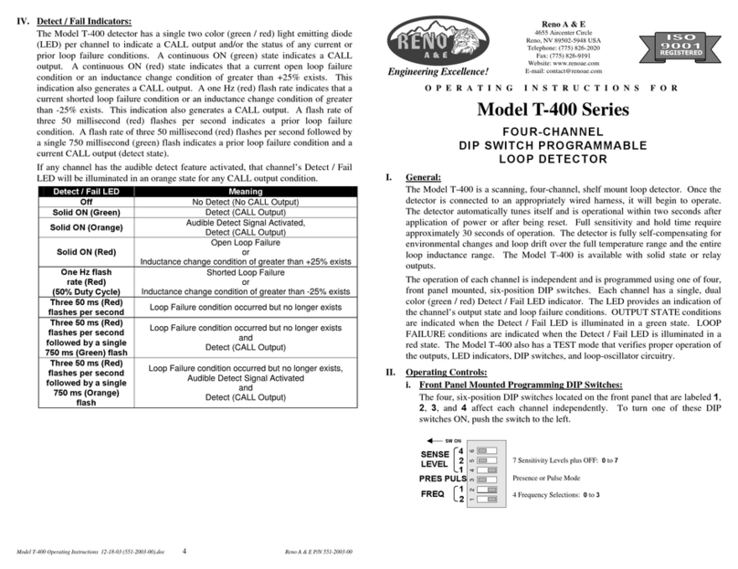
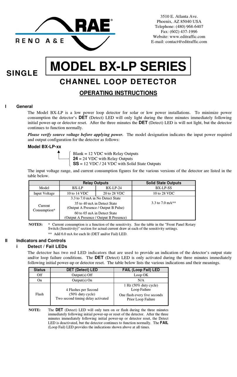
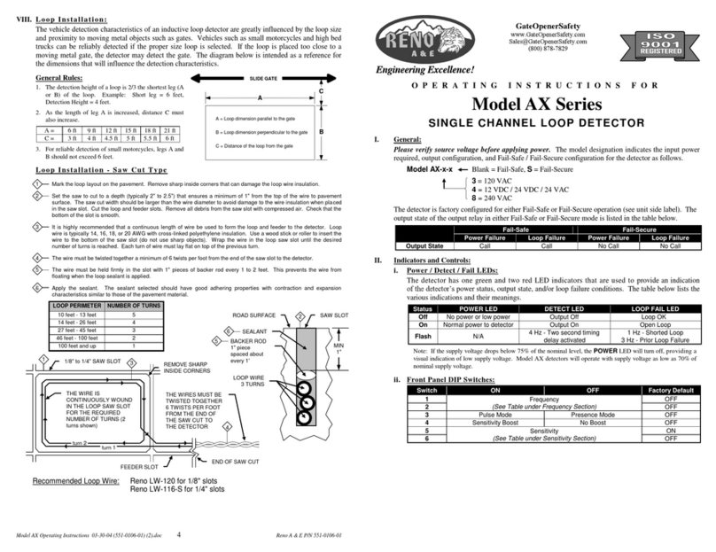
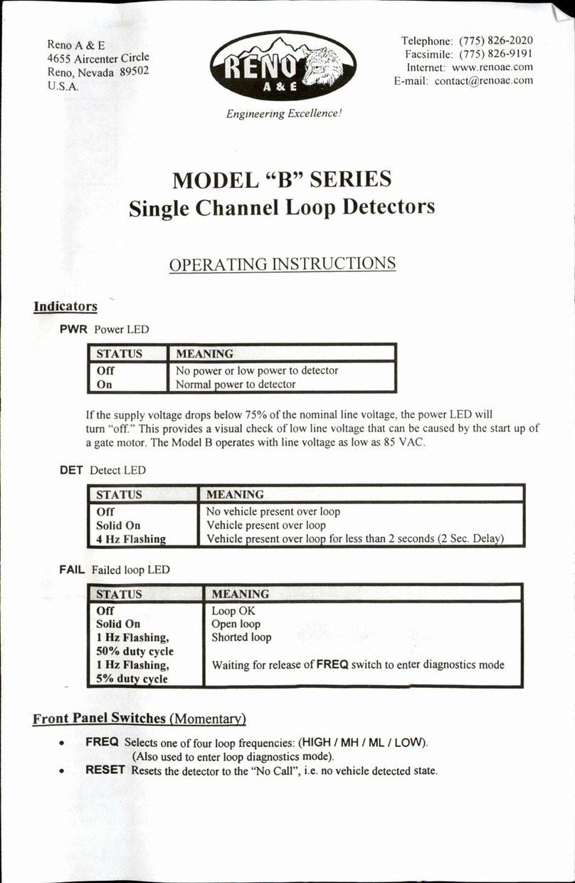
iii DIP Switches
Switch OFF ON Factory Default
1 OFF
2 Frequency
(See table in Frequency section) ON
3 Fail-Safe Fail-Secure OFF
4 No Boost Sensitivity Boost OFF
5 OFF
6 Detect Output Delay
(See table in Output Delay section) OFF
7 OFF
8 Detect Output Extension
(See table in Output Extension section) OFF
Frequency (DIP Switches 1 and 2)
When loops are located in close proximity to one another it may be necessary to
select different frequencies for each loop to avoid loop interference, commonly
known as crosstalk. DIP switches 1 and 2 can be used to configure the detector
to operate at one of four frequencies corresponding to Low, Normal, Medium,
and High as shown in the table below.
Frequency
Switch Low (0) Normal (1) * Medium (2) High (3)
1 ON OFF * ON OFF
2 ON ON * OFF OFF
* Factory default setting.
Fail-Safe / Fail-Secure (DIP Switch 3)
When DIP switch 3 is in the OFF position, the detector operates in Fail-Safe
mode. If a loop fault occurs when operating in Fail-Safe mode the Detect
Output is “ON”.
When DIP switch 3 is in the ON position, the detector operates in Fail-Secure
mode. If a loop fault occurs when operating in Fail-Secure mode the Detect
Output is “OFF”.
NOTES: Changing the setting of this DIP switch will reset the detector.
The factory default setting is OFF, Fail-Safe mode.
Sensitivity Boost (DIP Switch 4)
Sensitivity Boost is activated using DIP switch 4. When a vehicle is detected
sensitivity is automatically "boosted" to a higher level. The higher sensitivity
level remains until detection is dropped, at which time the sensitivity returns to
the no-detect level. This feature provides protection against dropping detection
when high bed vehicles pass over the loop.
NOTE: The factory default setting is OFF, no Sensitivity Boost.
3
Detect Output Delay (DIP Switches 5 and 6)
An Output Delay time of zero, two, five, or ten seconds can be programmed
using DIP switches 5 and 6. Output Delay time is the time before the Detect
Output activates following vehicle detection. If the Output Delay feature is
programmed to a value other than zero the Detect Output is "ON" only if a
vehicle is continuously detected for the programmed delay time. If vehicle
detection is lost during the delay time period the delay timer is reset to zero.
The next vehicle entering the loop detection zone starts a new delay time period.
The Detect LED flashes at a two Hertz rate (50% duty cycle) during the delay
time period.
Detect Output Delay Interval
Switch Zero (0)
Seconds * Two (2)
Seconds Five (5)
Seconds Ten (10)
Seconds
5 OFF * ON OFF ON
6 OFF * OFF ON ON
* Factory default setting.
Detect Output Extension (DIP Switches 7 and 8)
An Output Extension time of zero, two, five, or ten seconds can be programmed
using DIP switch positions 7 and 8. Output Extension time is the time following
the loss of detection before the Detect Output is dropped. If another vehicle
enters the loop during the extension time period the extension timer is reset to
zero, and a full extension time period follows the departure of the last detected
vehicle. The Detect LED flashes at a four Hertz rate (50% duty cycle) during
the extension time period.
Detect Output Extension Interval
Switch Zero (0)
Seconds * Two (2)
Seconds Five (5)
Seconds Ten (10)
Seconds
7 OFF * ON OFF ON
8 OFF * OFF ON ON
* Factory default setting.
III Detector Reset
The following actions perform Detector Reset:
1. Remove and reapply power.
2. Changing Fail-Safe / Fail-Secure setting. (DIP switch 3).
3. Momentarily connecting Pin 3 of the Molex connector to ground (0 to 2
VDC).
Detector Reset must be performed following any change in loop-operating
frequency. Changes in Sensitivity, Sensitivity Boost, Delay time, or Extension
time immediately take effect without the need to perform Detector Reset.
