Repak RE20 User manual

Repak
Phileas Foggstraat 18, 7821 AK EMMEN, The Netherlands.
Phone +31 (0)591 668010, Fax +31 (0)591 676076, www.repak.nl
User Manual
for the start-up and operation of the
Thermoforming Packaging Machine
part 1: operator

2
Repak RE20 User Manual
part 1: operator
Machine number: 2080791
Production date:20-02-2020
User Manual for RE20
Machine manufacturer:
Service department address:
Language: English
Repak B.V.
Version: 2.165b
Publication date: Jan 2019
Repak B.V.
Phileas Foggstraat 18
7821 AK Emmen
Tel: 0031-(0)591 668 010
Fax: 0031-(0)591 676 076
No part of this publication may be copied or given to third parties without the express permission of
Repak.

3
Foreword
The Repak RE20 is a modern deep drawing packaging machine for large to very large
numbers of packages. Its modular construction, designed for optimum hygiene, makes it
capable of handling a wide variety of applications.
This manual is divided into three parts: the operator manual (chapter 1), the technical part
with electrical and pneumatic diagrams (chapter 2 -11) and the spare parts list . (chapter
12). Part one contains all the information the operator requires to start the machine up and
run it. These are activities that do not require tools of any kind. The technical part describes
the electrical and pneumatic diagrams and the third part contains the parts lists and
construction drawings relative to the machine.
The standards that the machine meets are listed in the “EC declaration of compliance for
machines”.
In all cases and in case of dispute, the authoritative version remains the English version.

4
4
Declaration of Agreement
According to appendix II, part A of the Machinery Directive 2006/42/EG
Repak BV
Phileas Foggstraat 18,
7821 AK Emmen
Netherlands
Telephone +31(0)591-668010
Hereby declares, completely under its own responsibility, in relation to the following machine:
Horizontal shaping, filling and sealing machine, Repak RE20, RE2080791
- That it meets the applicable essential requirements of the Machinery Directive (2006/42/EG)
- That, in addition to the abovementioned Directive, the machine meets the conditions in the following Directive (s):
EMC Directive (2004/108/EG)
Authorised author(s) of the technical dossier:
Repak BV
Phileas Foggstraat 18,
7821 AK Emmen
Netherlands
The following European harmonised standards, or other normative documents, are applied:
-Basis terms, general design principles: Basic terms for design,
risk evaluation and risk reduction, NEN-EN-ISO 12100:2010
-Minimum distances. To prevent the entrapment of parts of the
human body, NEN-EN 349:1994+A1:2008.
-Safety of packaging machines.
Section 3: Shaping, filling and sealing machines, NEN-EN 415-
3:1999+A1:2009.
-Safety of machines. Safety distances to prevent the upper or lower
parts of the human body from entering dangerous zones, NEN-EN-
ISO 13857:2008.
-Machine safety. Emergency stop facilities, functional aspects,
design principles NEN-EN-ISO 13850:2008.
-Human body dimensions.
Part 1: principles for the determination of the required dimensions of
access openings in machines for the entire body, NEN-EN 547-
1:1997+A1:2008.
Part 2: principles for the determination of the required dimensions of
access openings, NEN-EN 547-2:1997+A1:2008.
Part 3: anthropomorphic data, NEN-EN 547-3:1997+A1:2008.
-Ergonomic design principles.
Part 1: terminology and general principles, NEN-EN 614-1:
2006+A1:2009.
Part 2: interaction between the design of machines and work tasks,
NEN-EN 614-2:2000+A1:2008.
-Safety of machines. General requirements for the design and the
protection of screens (fixed and movable), NEN-EN 953:
1998+A1:2009.
-Safety of machines. Parts of control systems with a safety function
- Part 1: general design principles NEN-EN 954-1:1997.
-Safety of machines. Parts of control systems with a safety
function. Part 1: general design principles, NEN-EN-ISO 13849-
1:2006.
-Safety requirements for hydraulic and pneumatic systems and
parts. Pneumatics, NEN-EN 983:1997+A1:2008.
-Safety of machines. De-activation of the power supply and removal
of power. Prevention of unintended starting, NEN-EN
1037:1996+A1:2008.
-Safety of machines. Blocking with or without blocking facilities.
General basic principles for the design, NEN-EN 1088:
1996+A2:2008.
-Conveyor belts for general use. Requirements for the electrical
safety and flammability, NEN-EN EN 12882:2008.
-Electromagnetic compatibility (EMC). General standards. Part 6-
2: Immunity for industrial environments, NEN-EN-IEC 61000-6-
2:2001.
Part 6-3: Emissions standard for household, trade and light
industrial environments, NEN-EN-IEC 61000-6-3: 2001.
-Safety of machines. Instructions, brands and operating principles.
Part 1: requirements for visible, audible and tangible signals; NEN-
EN 61310-1:2008.
-Contact-free electrical safety features. NEN-EN-IEC 61496-
1:2004.
-Points of departure for the coding of instruction features and
operating organs. NEN-EN 60073: 2002.
-Safety of machines –electrical equipment of machines.
Part 1: General requirements: NEN-EN-IEC 60204-1: 2006.
-Human-machine interface (MMI) –operating principles.
NEN-EN 60447: 2004
-Low-Voltage switching and distribution equipment.
Part 1: General requirement - NEN-EN-IEC 61439-1:2009.
Part 2: Voltage switching and distribution equipment.
NEN-EN-IEC 61439-2:2009.
Netherlands, Emmen, 20-02-2020
Name and function R. Scholte, General Manager
Signature

5
Table of contents
1Introduction.......................................................................................................... 6
1.1 Function ...........................................................................................................................6
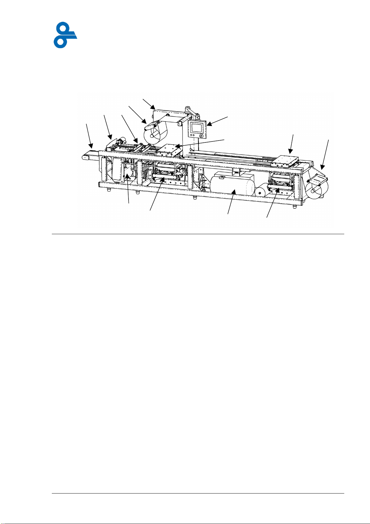
1.2 Most important parts ........................................................................................................7
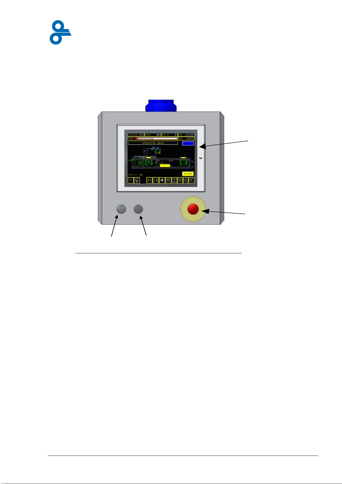
1.3 Control equipment............................................................................................................8
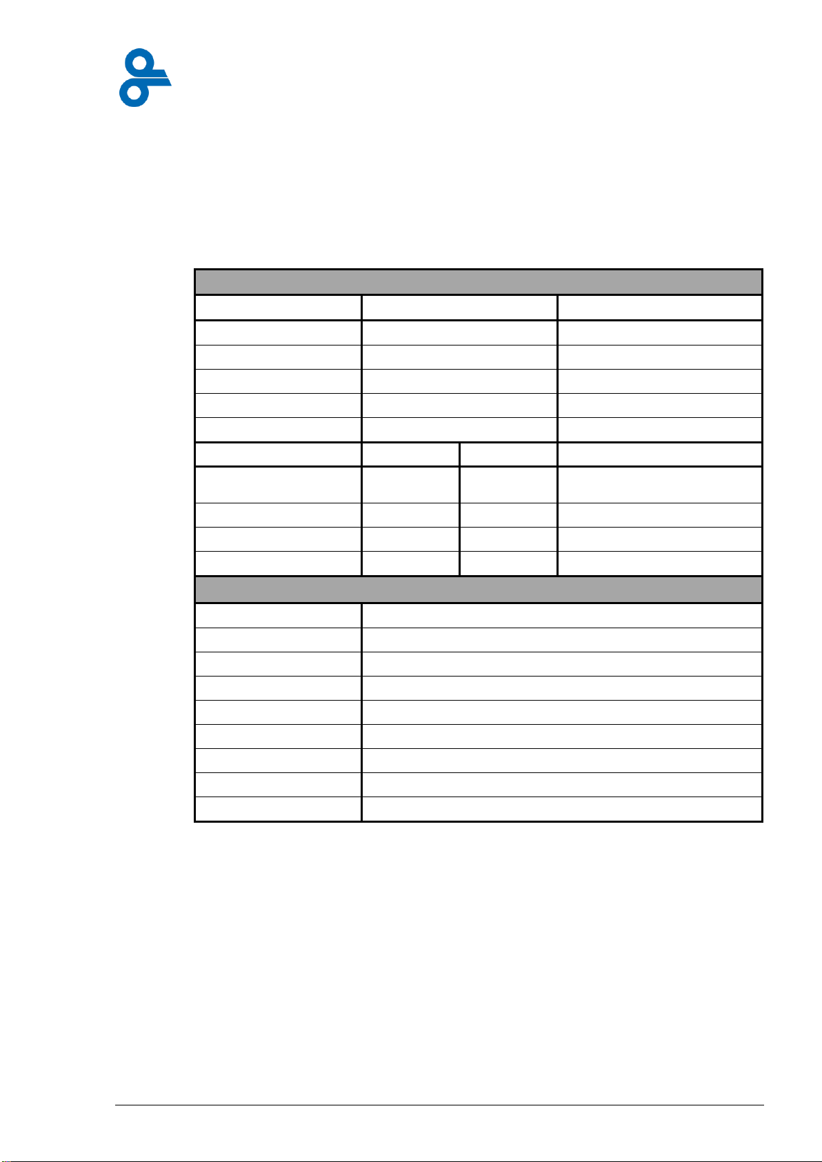
1.4 Technical specifications...................................................................................................9
2Preventive measures and safety instructions.................................................. 13
2.1 General safety instructions ............................................................................................13
2.2 Intended use and use not recommended ......................................................................15
2.3 Meaning of the symbols.................................................................................................16
2.4 Safety systems...............................................................................................................19
2.5 Transportation................................................................................................................23
3Description of the machine ............................................................................... 26
3.1 Operation .......................................................................................................................26
3.2 Description of machine frame ........................................................................................27
3.3 Description of bottom film unwind unit...........................................................................28
3.4 Description of forming station ........................................................................................32
3.5 Description of loading area ............................................................................................34
3.6 Top film unwinding unit ..................................................................................................38
3.7 Photocell and film brake.................................................................................................38
3.8 Description of sealing station.........................................................................................42
3.9 Cross cutting ..................................................................................................................43
3.10 Complete-cut punch (only available for RE25!) .............................................................48
3.11 Longitudinal cutters........................................................................................................49
3.12 Discharge conveyor belt.................................................................................................53
3.13 Control cabinet...............................................................................................................54
3.14 Drive gear.......................................................................................................................55
3.15 Film edge trim removal...................................................................................................56
4Control panel...................................................................................................... 59
4.1 How the touch screen works..........................................................................................59
4.2Machine operating menus..............................................................................................61
4.3 Operator menu...............................................................................................................65
4.4 Main menu .....................................................................................................................75
4.5 Access code.................................................................................................................101
5Operating the machine .................................................................................... 103
5.1 Preventive measures and safety instructions ..............................................................103
5.2 Turning on the machine ...............................................................................................106
5.3 Fitting the rolls of film...................................................................................................112
5.4 Setting the photocell.....................................................................................................115
5.5 Calibrate the photocell .................................................................................................116
5.6 Turning the machine off ...............................................................................................117
5.7 Operating the machine while it is running....................................................................117
5.8 Energy-saving operation..............................................................................................118
6Cleaning and maintenance.............................................................................. 120
6.1 Guidelines and methods ..............................................................................................120
6.2 Maintenance procedures..............................................................................................121
6.3 Maintenance instructions .............................................................................................126
6.4 Recording the maintenance and cleaning logbook......................................................134
7Overview of status lines .................................................................................. 136
7.1 Environmental factors ..................................................................................................136
7.2 Overview of status lines...............................................................................................137
7.3Defects affecting the film..............................................................................................139
8Explanatory list of words................................................................................. 140
9Appendix........................................................................................................... 144

6
1 Introduction
1.1 Function
The Repak RE20 is exclusively designed for the packaging of foodstuffs, consumables and
officially registered drugs (both must meet the local recommendations and laws applicable
locally) in hermetically sealed packs.
In order to achieve this the machine works as follows: film is held between two chains at the
infeed of the machine. The first processing of the film takes place in the forming die. Here a
shape is produced in the film by a combination of heat and pressure. In the next part of the
machine, the loading area, the shaped film pockets are filled with the product to be
packaged. In the next area, the sealing die, the top film is applied to the top of the pack and
sealed to it. During the sealing process the pack can, if so desired, be sealed under vacuum
or filled with gas. Subsequently the various packages are cut loose from one another and, if
required, holes are made in the packaging so that it can be hung up on a rack. The packaged
products are removed from the machine via a conveyor belt or a chute.

7
1.2 Most important parts
A diagrammatic figure of the machine is given below (Figure 1.1). The machine consists of
the following main parts:
Figure 1.1
1. bottom film unwind unit
2. forming station
3. sealing station
4. control panel
5. control cabinet
6. top film unwind unit
7. cross cutting unit
8. longitudinal cutting unit
9. conveyor belt
10. drive system
11. lifting system
12. vacuum pump
In addition to the parts shown here, the machine can also be fitted with various kinds of
peripheral equipment. This includes labeling equipment, filling machines, printing equipment
etc. Please refer to the relevant manuals for the operation of such equipment.
1.
2.
3.
4.
5.
6.
7.
8.
9.
10.
12.
11.
11.

8
1.3 Control equipment
The machine is mainly run from the control panel fitted to the control cabinet.
All the machine’s functions, such as temperature or choice of packaging program, can be
operated via a touch screen (see Figure 1.2).
There is a complete description of the touch screen in the chapter entitled “Control
Panel”.
In addition to the control panel the machine also has a number of other control
mechanisms. These are exclusively for the use of the technical department or the
supplier and they are not dealt with in this part of the manual.
Touch screen
Emergency button
start button
stop button
Figure 1.2 Touch panel

9
1.4 Technical specifications
The specifications dealt with in this manual are limited to the activities permitted at operator
level. Extensive technical information, such as electrical and pneumatic diagrams, can be
found in Part 2 of the manual. Some operational characteristics of the machine are given in
Table 1.
Table 1 Operational characteristics
Electrical connection values and immediate environmental requirements
Value
Remarks
Current
3* 230/400 V 50-60Hz
3*230V 60HZ (USA,CA)
Phase
3Ph N PE
3 Ph PE (USA,CA)
Power
~15 kW*
Nominal current
35 A (35 A fuses)*
Noise level
70 dB
Minimum
Maximum
Water
0.5 bar
3 bar
⅜ “, 60 liters/hr
(20 Gallons/hour)
Pressed air (dry)
6 bar
7 bar
90PSI, 35 CFM
Gas
4 bar
6 bar
Relative humidity
-
70%
System characteristics
Dimensions (l x w x h)
RE20: 4000-5000-6000 x 1050 x 1950 mm.
Weight
ca. 2200-2600 kg (incl. Vacuum pump)
Film unwind unit
single-sided suspension, passive braking
Conveyor belt
drum motor, max. 1.2 m/s
Free loading area
RE20: ~800-1800 mm
Working height
950-1040 mm
Film width
320-420-460 mm
Max. stroke length
600 mm
Max. packaging height
120 mm
(*) depending on machinery configuration.

10
1.4.1 Performance
The performance of the machine is indicated for use under normal conditions. This implies
the following:
-The machine is used in a roofed industrial hall that can be closed off so that both
machine and operator are protected from the outside environment and from third-
party activities;
-There is sufficient light for the operator to be able to follow the machine’s processes,
namely a minimum of 500 lux;
-The area is equipped with adequate climate control equipment that regulates the
humidity levels, max. 70%, min. temperature 4 C (39 F) and max. temperature 40 C
(104 F)
-The machine should not be exposed to extreme vibration levels, no more than 2 G
-The working area should comply with hygienic recommendations usual in the food
processing industry, e.g. the HACCP in Europe
The machine capacity depends on the duration of the packaging program chosen. The
machine can achieve an average of 12 cycles per minute. The duration of a program is
affected by:
-The dimensions of the packaging (length, width and height);
-The type of film used;
-The safety pauses between the stages;
-The final vacuum required in the packaging;
-Etc.
For a machine to work optimally the program settings must be fine-tuned by trained staff.
Influences from the immediate environment
The principal condition for the machine to operate correctly is constant quality of water,
compressed air, the vacuum equipment and the gas. This means, for example, that if the
cooling water has a higher temperature this will lead to less cooling and badly shaped
packaging. The condition of the air in the space where the machine is situated is also
important. Deviation from these values can lead to breakdowns in the machine. Chapter 0
deals with these matters.
1.4.2 Contents of the order supplied
When the machine is delivered, the following are included:
-1 packaging machine plus die sets;
-Manual.
-One toolbox.
-One transport crate and 4 transport blocks.
-Storage case for the longitudinal cutter blades.

11
1.4.3 Disposal of the Repak machine
Final decommissioning and disposal requires the complete disconnecting of the entire power
supply system.
At the end of its service life, the machine should be dismantled properly and disposed of in
accordance with national regulations.
Ensure the following while disposing of components of the machine:
-Send metal parts for recycling
-Send plastic parts for recycling
-Send electrical and electronic components for hazardous waste disposal
Recommendation:
-Contact a company specialised in disposal!

12
Contents
2Preventive measures and safety instructions.................................................. 13
2.1 General safety instructions ............................................................................................13
2.2 Intended use and use not recommended ......................................................................15
2.3 Meaning of the symbols.................................................................................................16
2.4 Safety systems...............................................................................................................19
2.4.1 Protection covers..................................................................................................20
2.4.2 Metal cover plates................................................................................................21
2.4.3 Side plates............................................................................................................21
2.4.4 Emergency switch................................................................................................22
2.4.5 Pressure switches ................................................................................................22
2.5 Transportation................................................................................................................23

13
2 Preventive measures and safety instructions
This chapter lists the general safety instructions and explains the symbols used on the
machine. The chapter makes clear the dangers that can arise in the various parts of the
machine. The safety of the user is ensured by a variety of instructions and
recommendations. Anyone working with or on the machine is obliged to observe all
instructions and recommendations.
2.1 General safety instructions
The following general safety instructions apply to the use of the machine by the operator:
-Before using the machine, read and study the operator manual.
-Operating the machine is reserved to the authorised and trained operator.
-Never leave the machine turned on and unsupervised.
-Always take into account, without exception, all the warnings in this manual
and posted on the machine.
-Always follow the factory recommendations applicable.
-In dangerous situations, always press the emergency button immediately. For further
information on the emergency button, please refer to paragraph 5.2.
-After pressing the emergency button you should not turn on the machine again unless
you are sure that the situation is no longer unsafe.
-When working on the machine, turn off the power and the air supply unless otherwise
indicated. Shutting off the air supply immobilizes the moving parts and the blades.
-Repairs are to be carried out exclusively by Repak or by an expert trained by Repak.
-It is not allowed to make adjustments to the machine without written approval from
Repak B.V.
-Use the built-in safety systems and maintain them. Making changes to or adding
short circuits to these systems is strictly forbidden and cancels all warranties.
-Do not run the machine unless all protective safety covers and side plates are
present and in place. If you have any doubts, consult the technical department.
-Never at any time must you remove the safety covers. This is never required when
the machine is working appropriately.
-When moving heavy parts (mass > 25 kg), such as film rolls or forming dies, use an
approved lifting device.
-The edges of the film can be very sharp and cause wounds. Wear protective
clothing.
-When the machine is running the operator may carry out activities only in the zones
indicated in Figure 2.1.
-Ensure that used oil is disposed of appropriately. It should be placed with the
chemical waste, as recommended by the government.
-Remains of film should be placed in the appropriate container as recommended by
the government.
-Observe the rules of hygiene when handling foodstuffs.
Figure 2.1 Operator’s activity zones

14
-When turning off the main switch (see Figure 2.2) secure it with a lock in order to
prevent unforeseen switching on or off by other persons.
-Supplementary installations such as labelling equipment, filling machines, printing
equipment etc. usually have their own power supply. This should be turned on and off
separately during maintenance work according to the manuals applicable to the
equipment.
-The cables connecting the control cabinet and the external equipment should be so
arranged that nobody can trip over them.
-Observe the safety guidelines contained in the manuals for the supplementary
equipment.
-Keep your body parts well away from rotating components such as the blades and
film unwind units.
-Do not wear loose clothing.
-Do not wear chains.
-Do not have your hair long and loose.
-Never interfere with a machine while it is running.
-During operation of and maintenance to the machine be careful of projecting parts so
that you do not bump against them.
Figure 2.2 Main switch

15
2.2 Intended use and use not recommended
In the interests of the user’s safety and in order to prevent damage to the machine the
following rules should be strictly adhered to. Failure to follow these rules can lead to serious
accidents. Repak BV cannot be held responsible for accidents resulting from a failure to
follow these rules or any other warning stated in this manual.
-The machine may only be used for packaging foodstuffs, medicines and medical
equipment. It is absolutely forbidden to package any livestock.
-The machine may only be used with packaging film approved by Repak B.V.
-The machine may only be used under conditions detailed in the technical
specifications.
-Do not start the machine up without covers, side plates, roller conveyor and safety
covers.
-Never use the machine without a support tray.
-Do not wear any rings on the hands nor a chain or wristwatch while the machine is
running.
-Never interfere with the machine’s moving parts.
-Use ear protection when the machine is running.
-Working with the machine is only permitted after user instructions have been received
from Repak or one of its agencies.
-Unauthorized or uninstructed persons are not permitted to be within 1 meter of the
machine.
-It is not permitted to run the machine if a defect has been noted.
-It is not permitted to lean on parts of the machine.
-It is not permitted to stand or sit on the machine.
-It is not permitted to place anything on the machine.
-It is not permitted to use high pressure spraying equipment on the machine.
-It is not permitted to change parts or systems on the machine or to change their
function without written approval from Repak.

16
2.3 Meaning of the symbols
The machine has several danger zones. A danger zone is an area where various types of
danger are present that can seriously wound the person using the machine. Figure 2.3
indicates the various danger zones and warnings.
Figure 2.3 Danger Zones
No.:
Machine part:
Dangers:
1.
Film infeed
2.
Forming station
3.
Sealing station
4.
Cross cutter
5.
Longitudinal cutter
6.
Control cabinet
7.
Main motor
8.
Lifting equipment
9.
Vacuum pump
10.
Drive chains
11.
Conveyor belt
10
00
00
00
.
2.
3
.
6.
4
.
5.
11
.
7
.
9
.
8
.
8
.
1
.

17
Safety plates and covers make it impossible to come into direct contact with most of the
danger zones. Warnings are given in this manual relative to specific dangers in each zone.
These warnings are repeated on the safety covers (see Figure 2.4). The dangers existing
within each zone are explained in Table 2.
Table 2 Explanation of the danger symbols
Meaning
Danger of death! High voltage
Danger
Live parts that can lead to electrocution.
Recommendation
Work on the switch box may only be carried out by an authorized
electrician.
Can be found in:
control cabinet (6), main motor (7), longitudinal cutter motor (5),
and vacuum pump (9).
Meaning
DANGEROUS! Rotating parts.
Danger
Among other things, rotating parts can crush limbs.
Recommendation
Approach rotating parts only when the machine is turned off.
Do not wear loose clothing.
Do not wear chains.
Do not have your hair long and loose.
Do not interfere with the lifting equipment.
Can be found in:
forming station (2), sealing station (3), film infeed (1), transport
chains (10), longitudinal cutter (5), conveyor belt (11), chain drive
(7)
Meaning
DANGEROUS! Component closes
Danger
Parts that close forcefully and can amputate limbs
Recommendation
Never interfere with the machine when it is turned on.
Never remove the safety covers and never shut them down.
Can be found in:
Lifting equipment (8), longitudinal cutter (4).

18
Meaning
DANGEROUS! Rotating blades
Danger
(Rotating) blades can cause cuts or amputate limbs.
Recommendation
Do not carry out any activities within the reach of the blades.
Never take hold of blades by the cutting edge.
Always place blades in a safe place.
NB! The sealing die bottom part has blades on the gas channels.
Always take hold of the blade shaft of the longitudinal cutter on the
outside.
During maintenance work always place the blade shaft in the
protective cover supplied.
Can be found in:
longitudinal cutter (4), longitudinal cutter (5), sealing station (3).
Meaning
DANGEROUS! Hot surface
Danger
Hot components can cause serious burns.
Recommendation
After the main switch has been turned off, hot components need a
considerable amount of time to cool down (approximately 1 hour).
Wear protective gloves.
Take hold of hot components by the edge and place them in a safe
place.
Can be found in:
sealing die bottom part (3), sealing die top part (3), forming die top
part (2).

19
2.4 Safety systems
The machine is fitted with a number of safety systems. The systems consist mainly of plastic
covers, metal covers and side plates (see Figure 2.4). In addition to the main switch, the
pressure switches and the over-pressure valves are part of the safety system.
Figure 2.4 Safety systems
Removable safety covers:
1. sealing station;
2. forming station outfeed;
3. forming station infeed;
4. longitudinal cutter and cross cutter;
5. space between chain track and machine frame.
Fixed safety covers:
6. end parts of conveyor belt;
7. support tray;
8. forming station infeed;
9. film infeed;
10. underside of conveyor belt;
11. drive belt;
12. top film infeed;
13. chain cogs;
14. longitudinal cutter blades;
15. machine side plates.

20
2.4.1 Protection covers
The 5 cover plates on the machine screen dangerous components from the outside world
(see Figure 2.5).
Because of this, the machine can only be switched on when all the plates are in place. To
this end the removable plates are fitted with magnets and the machine has magnetic
sensors. Lifting or removing a protective plate causes the machine’s process to stop. In order
to re-start the machine the plate must be replaced and the start-up procedure repeated (see
paragraph 5.2.5.2). The plates on the machine are not interchangeable so always put them
back in the correct place. If the plates are placed in the wrong place an error message is
displayed in the control panel status line. In order to guarantee that the covers work properly,
both they and the surfaces on which they rest must be clean. Damaged covers should be
replaced immediately. The cover on the exit side of the forming station is fitted with fingers to
prevent access to the lifting system.
Figure 2.5 Cover plates
Table of contents
Popular Packaging Equipment manuals by other brands

LERICA
LERICA C254 Operating and service manual

Advanced Poly-Packaging
Advanced Poly-Packaging T-300 Operation guide

Imetec
Imetec Q5901 Instructions for use

U-Line
U-Line H-2079 manual

ITATOOLS
ITATOOLS ITA14 Operation manual and spare parts list

Signode
Signode TENSION-WELD VFX-9/13 Operation, parts and safety manual